

Page 1
Operator’s Manual
Portable Radio Unit
KPC-300/400
E
Page 2

NO TICE!
This manual covers Ericsson and General Electric products
manufact ured for and sold by Ericsson Inc.
NOTICE!
Repairs to this equipment should be made only by an authorized service technician or facility designated by the supp lier.
Any repairs, alterations or substitution of recommended parts
made by the user to this equipment not approved by the
manufacturer could void the user’s authority to operate the
equipment in addition to the manufacturer’s warranty.
NOTICE!
The software contained in this device is copyrighted. Unpublished rights
are reserved under the copyright laws of the United States.
This manual is publi shed by
ments and changes to this manual necessitated by typographical errors,
inaccuracies of current information, or improvements to programs and/or
equipment, may be made by
Ericsson Inc.,
Ericsson Inc
without any warranty. Improve-
., at any time and wi thout notice.
Such changes will be incorporat ed i nto new editions of thi s manual. No part
of this manual may be reproduced or transmitted in any form or by an y means,
electronic or mechanical, including photocopying and recording, for any
purpose, without the express written permission of
Copyright © May 1996, Ericsson Inc.
2
Ericsson Inc.
Page 3

TABLE OF CONTENTS
INTRODUCTION . . . . . . . . . . . . . . . . . . 5
CONTROLS . . . . . . . . . . . . . . . . . . . . . 10
INDICATORS . . . . . . . . . . . . . . . . . . . . 13
STATUS INDICATORS . . . . . . . . . . . . . . 14
ALERT TONES . . . . . . . . . . . . . . . . . . 15
Power-up Self-test . . . . . . . . . . . . . . 15
Carrier Control Timer . . . . . . . . . . . . . 16
Channel Busy Lock-out . . . . . . . . . . . 16
Type 99 Al ert Tone . . . . . . . . . . . . . . 16
ANI Alert Tone . . . . . . . . . . . . . . . . 17
Scan Alert Tone . . . . . . . . . . . . . . . 17
Priority-One (P1) Scan . . . . . . . . . . . . 17
Radio/Chan ne l Failure . . . . . . . . . . . . 17
OPERATION . . . . . . . . . . . . . . . . . . . . 18
RECEIVING A MESSAGE . . . . . . . . . . . . 18
SENDING A MESSAGE . . . . . . . . . . . . . 19
SQUELCH ADJUST (FRONT PANEL) . . . . . . 20
TYPE 99 OPERATION . . . . . . . . . . . . . . 20
Type 99 Selective Call Recei v ing
and Sending . . . . . . . . . . . . . . . . . 21
SCAN OPERATION . . . . . . . . . . . . . . . . 22
Starting Or Stopping Scan . . . . . . . . . . 23
Receiver Scan Rate . . . . . . . . . . . . . 23
Adding Channels To Scan List . . . . . . . . 26
Deleting Channels From Scan List . . . . . . 26
Using The Radio With Scan . . . . . . . . . 27
The Selected Channel . . . . . . . . . 27
Scanning With Channel Guard . . . . . 28
TELEPHONE INTERCONNECT CALLS
(KPC-400 ONLY) . . . . . . . . . . . . . . . . . 28
Pre-program me d Num ber . . . . . . . . . . 29
Placing A Manually Dialed Call . . . . . . . 30
EMERGENCY OPERATION . . . . . . . . . . . 30
BATTERY INFORMATION . . . . . . . . . . . . . 31
3
Page 4

CHARGE BEFORE USING . . . . . . . . . . . 31
RECHARGING THE BATTERY . . . . . . . . . 31
CONDITIONING THE BATTERY . . . . . . . . . 32
INSTALLING THE BATTERY PACK . . . . . . . 32
REMOVING THE BATTERY PACK . . . . . . . . 33
BATTERY CARE & MAINTENANCE . . . . . . . 33
BATTERY RECYCLING . . . . . . . . . . . . . 34
OPERATING TIPS . . . . . . . . . . . . . . . . . 34
EFFICIENT RADIO OPERATION . . . . . . . . 35
ANTENNA CARE AND REPLACEMENT . . . . 35
ELECTRONIC DEVICES . . . . . . . . . . . . 36
AIRCRAFT . . . . . . . . . . . . . . . . . . . . 36
BLASTING AREAS . . . . . . . . . . . . . . . 36
POTENTIALLY EXPLOSIVE
ATMOSPHERES . . . . . . . . . . . . . . . . . 36
ACCESSORIES . . . . . . . . . . . . . . . . . . 37
INTRINSICALLY SAFE USAGE . . . . . . . . . . 39
BATTERY PACKS . . . . . . . . . . . . . . . . 39
ACCESSORIES . . . . . . . . . . . . . . . . . 40
SWIVEL MOUNT REMOVAL AND
REPLA CEMENT . . . . . . . . . . . . . . . . . . 41
WARRANTY . . . . . . . . . . . . . . . . . . . . 42
NICKEL-CADMIUM BATTERY WARRANTY . . . 43
4
Page 5

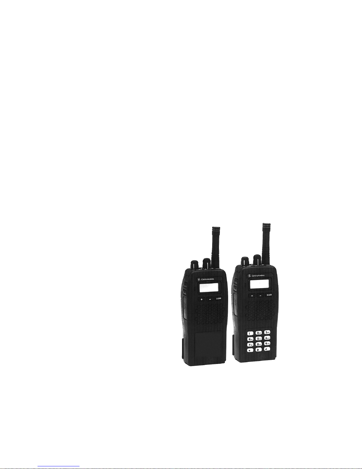
INTRODUCTION
The KPC-300 (Scan) and KPC-400 (DTMF) portable
radios are lightweight, full-featured radios that provide
reliable two-way communications on 1 to 16 channels.
The KPC-300 radio contains three (3) buttons on the
front panel. The KPC-400 contains three (3) buttons
along with a twelve (12) button DTMF pad on the front
panel. The scan function allows monitoring of any or all
channels. Any channel may be scanned with or without
a priority level. One channel can be programmed for
Priority 1 (P1) and another for Priority 2 (P2), with any or
all remaining channels programmed as non-priority
channels (S). There is also Emergency mode transmission capability. A LCD display provides status display of
the radio functions along with the display of the selected
channel number.
The Universal Device Connector (UDC), located on
the side of the radio, provides connections for external
audio accessories. This connector also allows the radio
system personnel to connect programming equipment
and program the per-channel and ov er all r adio features.
Consult the radio dealer to deter mine the programmed
features of your radio. Features that are programmable
on a per-channel basis include:
•
•
•
Receive Frequency
Transmit Frequency
Channel Busy Lock-Out
•
•
•
Squelch Tail Elimination (STE)
Channel Guard Encode/Decode (Tone or Digital)
Type 99 Tone Decode
5
Page 6
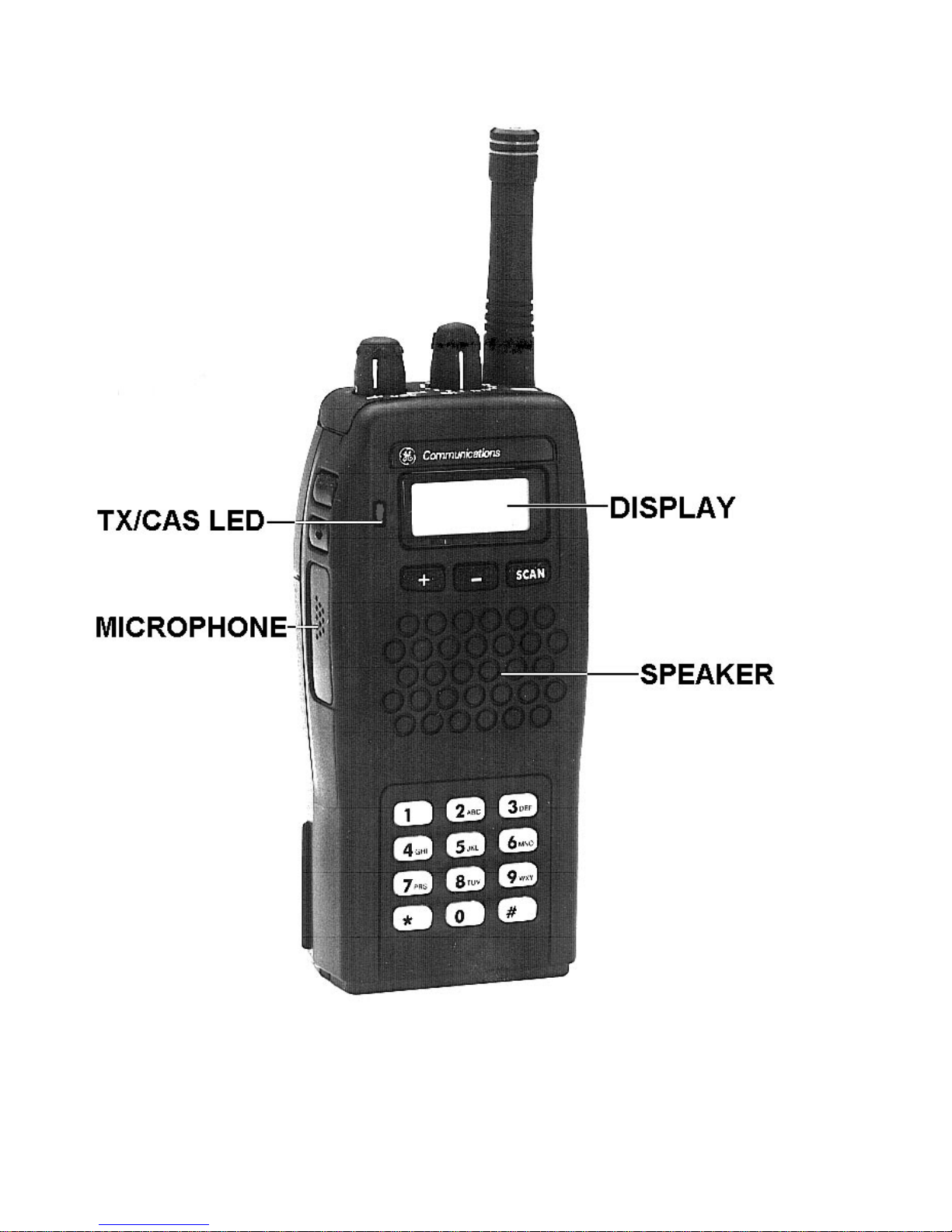
Figure 1 - System Radio
6
Page 7
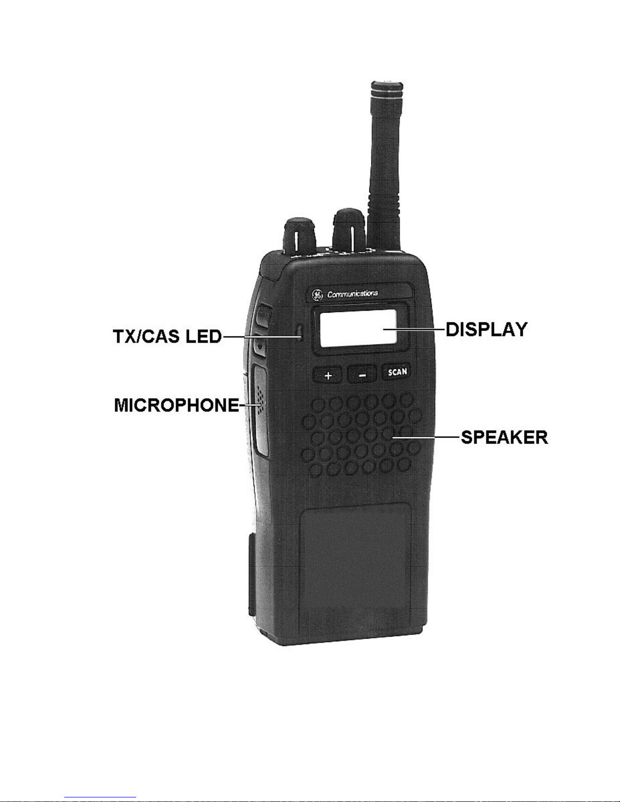
Figure 2 - Scan Radio
7
Page 8

•
Automatic Number Identification (ANI)
•
•
•
•
•
basis include:
•
•
•
RF Power (High or Low)
Receive Frequency Microprocessor Oscillator Shift
Transmit Frequency Microprocessor Oscillator Shift
Channel Spacing (12.5 kHz or 25/30 kHz)
Telephone Interconnect DTMF K eypad enable
(KPC-400)
Features that are programmable on an overall radio
Display Backlighting
Alert Tones
Emergency HOME Channel
•
•
•
•
Three (3) Auto-Dial Telephone Numbers
(KPC-400 only)
Carrier Control Timer (CCT)
Hi/Low RF Power Button Enable/Disable
Scan Options
8
Page 9
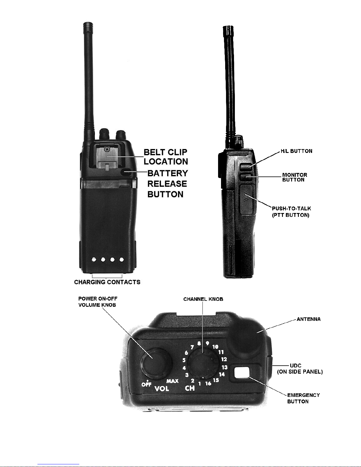
Figure 3 - To p, Back And Left Pa ne l Vie ws
9
Page 10

CONTROLS
ON/OFF/
VOLUME
-
Tur ns radio on and off and adjusts
audio listening lev el.
When the radio is turned on, it will
resume operation at the last operating state (channel, etc.) and the
power-up alert tones will be
sounded. Three (3) beeps indicate
the radio is in the normal (receive
mode); four (4) beeps indic ates the
radio is scanning. The operating
status of the radio will be displayed
in the Liquid Crys tal Display (LCD)
window.
PTT BUTTON
-
Pressing the PTT button on the side
of the radio will key the radio transmitter.
If the radio is not scanning, it will
transmit on the selected (displayed)
channel. If the radio is scanning
when the PTT button is pressed, the
radio may be programmed to transmit on the selected channel or on
the current receive scan channel if
the PTT is pressed during the sc an
hang time.
If the selected channel is pro-
10
grammed with T ype 99 T one Decode
enabled, pressing the PTT button
Page 11

will disable Type 99 Tone Decode by
switching the radio from the Selective Call mode to the Monitor mode .
The PTT button must be released
and then pressed a second time to
ke y the radio .
MONIT OR
-
The Monitor button has several
functions. Its operation will vary depending upon programming.
When the Monitor button is pressed
and held down, all transmissions will
be heard even if Channel Guard protected. This permits channel monitoring before transmitting. If the button is held for more than one second, Channel Guard decode will
toggle ON or OFF (if it is programmed on the selected channel).
The Monitor button is also used to
CHANNEL
SELECT
reset the radio after a Type 99 call is
received. Quickly press and release
the button to reset the radio to receive the ne xt Type 99 call.
-
A rotar y switch per mits selection of
channels. Rotating the s witch clockwise increases the channels and
counterclockwise decreases the
channels. The channel is v isible by
looking at the channel switch from
the top or viewing the LCD display.
11
Page 12

EMERgency
-
Pressing for at least one (1) second
will transmit the emergency ANI
code on the selected channel or preprogrammed HOME channel.
H/L
Three (3) buttons below the LCD display are used to
control scan and squelch adjust operations when used
in conjunction with the
S
+
-
Pressing for at least one (1) second
selects the transmit power output by
toggling from high-low or low-high.
Must be pre-programmed f or operation.
S
-
Toggles the scan feature on and off.
-
Used in conjunction with the
button to add channels to the scan
list or increase the channel’ s priority
button.
S
-
status.
-
Used in conjunction with the MONI-
TOR button to enter the squelch adjust mode; then used to increase the
lev el of squelch.
-
Used in conjunction with the
button to erase the selected channel
from the scan list.
-
Used to decrease the level during
squelch adjust mode.
S
12
Page 13

DTMF Keypad
-
P ermits operator to make telephone
(KPC-400)
The Liquid Crystal Display (LCD) indicates the channel number . In addition there are se ven (7) status indicators (flags) which show scan status, Type 99 Tone Decode status, transmit High/Low power status and Chan-
interconnect calls on radio systems
equipped with this option.
The top row of buttons (
3
pre-programmed telephone interconnect numbers (see Telephone
Inter connect Calls section).
) provide access to up to three
INDICATORS
1, 2
,
nel Guard status.
The LCD backlighting will turn on anytime a control
button is pressed. It will remain on for five (5) seconds
after the button is released. If a control button is pressed
while the backlight is on, the backlight remains on for
another five (5) seconds. Backlighting may be programmed to remain off at all times.
SCN HI
S P1 P2
PG CG
Figure 4 - Liquid Crystal Display (LCD)
13
Page 14

CHANNEL
-
The selected channel number is displayed in the LCD window. When
12
data is written into or read from the
radio during PC programming, a P is
displayed.
STATUS INDICATORS
SCN
S
P1
P2
-
This status indicator tur ns on when
the scan function of the radio has
been enabled.
-
When this indicator is on, the selected channel is a non-priority scan
channel.
-
When this indicator is on, the selected channel is a Priority 1 scan
channel.
-
When this indicator is on, the selected channel is a Priority 2 scan
channel.
PG
CG
-
-
14
When this indicator is on, the selected channel is programmed as a
paging channel (Type 99 Tone Decode). The indicator will blink when
the selected channel is placed in the
monitor mode or the reception of a
call.
When this indicator is on, Channel
Guard is enabled on the selected
Page 15

channel. The indicator will go out
when the selected channel is placed
in the monitor mode.
HI
TX/CAS LED
ALERT T ONES
-
When this indicator is on, the selected channel is enabled for transmit high power .
-
Red light on steady - transmitter is
active or key ed.
Red light blinking - low battery volt
age, recharge or replace battery
Green on steady - channel busy indication, radio has detected a carrier
on selected channel.
Aler t tones or “beeps” are sounded when some buttons are pressed and when the operating status of the
radio changes. All alert tones may be programmed to be
remain off. The volume level of alert tones or "beeps"
can be changed by the volume control.
Power-up Self-test
Each time the radio is turned on, it will perform
power-up self-test. All display segments will turn on, and
after successful completion of the test, the radio will
change to the last operating state (channel, etc.) and
sound three (3) or four (4) beeps . Three (3) beeps sound
if the radio is operating in the normal (not scan) state.
15
Page 16

Four (4) beeps will sound if the radio is scanning. The
status will be indicated in the LCD. If the radio fails the
self-test, no beeps will be sounded.
Carrier Contr ol Timer
This feature, programmable on a per-radio basis,
prev ents unnecessary channel traffic and radio damage
if the transmit timer limit is e xceeded. If the programmed
timer times-out during a transmission, the radio will beep
and stop transmitting. The beeping tone will continue until
the operator releases the PTT button. Releasing the PTT
button resets the timer.
Channel Busy Lock-out
If channel busy lock-out has been programmed on the
selected channel, the transmit function will be inhibited
when the operator press the PT T button while the radio
detects a carrier on the channel unless the carrier is
modulated with the corresponding Channel Guard tone
or code for that selected channel. Channel busy lock-out
continues to function if Channel Guard decode is disabled with the MONITOR button. The channel-busy fea-
ture is programmable on a per-channel basis.
T ype 99 Alert Tone
The Type 99 alert tone, indicating a receive Type 99
call, may be enabled or disabled by programming. If the
programmed tone sequence is detected, the radio will
beep until the second paging tone expires. If the alert
tones are disabled, no aler t tones will be present when
a Type 99 call is received.
16
Page 17

NOTE
The Type 99 alert tones can only be turned off by
disabling ALL alert tones.
ANI Alert Tone
The Automatic Number Identification ( ANI) alert tone
beep can be enabled or disabled by progr amming. If the
aler t tone is enabled, a beep will sound after the PTT is
pressed to indicate to the operator to begin voice transmission. Some communication systems require a time
delay befor e voice transmission begins. If the aler t tone
is disabled, no beep will sound.
Scan Alert Tone
The radio will sound a beep when the
S
button is
pressed.
Priority-One (P1) Scan
If the Priority 1 alert tone is enabled by programming
and the radio receives a signal on the Priority 1 channel
when scanning, the radio will sound a beep.
Radio/Channel Fa ilure
The simultaneous flashing of the LCD display and the
sounding of beeps indicates the synthesizer is unable to
correctly lock on the selected channel. At this time the
radio changes to a mute condition and no audio is heard
17
Page 18

from the speaker when receiving and the transmit is
inhibited if the PTT button is pressed. Select another
channel, change the battery pack or have the radio
repaired.
OPERATION
RECEIVING A MESSAGE
1. Turn the radio on by rotating the ON/OFF/VOLUME
control clockwise from the “off” detent. After the radio
has successfully completed its power-up self-test, it
will begin operation at the last operating state (channel, etc.). The operating status of the radio will be
display ed on the LCD. If enab led, the po wer-up alert
tones (three or four beeps) will be sounded.
2. Select the desired operating channel by rotating the
CHANNEL SELECT control until the des ired channel number appears on the LCD.
3. When a transmission is received (and the correct
Channel Guard or Type 99 signal is decoded, if
programmed and enabled), the receiver will unsquelch and the message will be heard in the
speaker.
4. Adjust the volume as necessary by rotating the
ON/OFF/VOLUME control.
18
Page 19

NOTE
Pressing the MONITOR button unsquelches the
receiver for the first three (3) seconds the button
is held. All transmissions will be heard, even if
Channel Guard protected. If it is held for more
than three (3) seconds, Channel Guard will be
toggled on or off (if programmed f or the selected
channel).
SENDING A MESSAGE
1. Turn the radio on and select the desired operating
channel as described in
RECEIVING A MESSAGE
.
2. Press the MONITOR button to determine if the chan-
nel is in use or observe the TX/CAS LED which shows
green if the channel is busy.
Never interr upt another
transmission.
3. Hold the radio so the antenna is vertical and press
and hold the PTT button when you are ready to
transmit. Speak directly into the grill or across the face
of the radio or external microphone. Release the PTT
button when y ou are finished talking. Messages cannot be received and heard when the PTT button is
pressed.
19
Page 20

NOTE
When transmitting on a paging channel (Type 99,
if programmed), the PTT button must be pressed
twice. The first press takes the radio out of
Selective mode. The second press keys the
transmitter for normal transmitter operation.
SQUELCH ADJUST (FRONT PANEL)
The squelch may be r e-adjusted from the front panel
using the MONITOR button and the + or
-
key. The
radio must not be in the scan or the emergency operation
mode when this adjustment is made.
1. Press and hold the MONITOR b utton while pressing
the + ke y to enter the squelch adjust mode. The digit
9 appears at the right side of the display.
2. To increase the level (i .e., requires stronger signal to
open squelch), press the + key . T o decrease the level
(i.e., requires weaker signal to open squelch), press
the - key.
3. To exit from this mode, press the MONITOR button.
The display returns to normal.
TYPE 99 OPERATION
The radio may be programmed to power up in the
Selective mode or in the Monitor mode. If the Selective
mode is programmed and a Type 99 channel is selected
at power up, the PG status flag will illuminate. If the
20
Page 21

Monitor mode is programmed and a Ty pe 99 channel is
selected, the PG status flag will blink.
When the radio is operating in the Selective mode, it
operates as a tone and voice receiver and only those
calls that are coded for it will be heard.
When the radio is operating in the Monitor mode, all
calls (with correct Channel Guard, if programmed) will be
heard.
In either mode, when a Type 99 channel has been
selected and a valid code is received, a series of alert
tones (if programmed) will alert the operator of the incoming call. If the radio is in the Selective mode, it will
automatically switch to the Monitor mode after the detection of the second Type 99 tone.
NOTE
If the radio was programmed to power up in the
Selective mode, changing positions on the
channel select switch will always place a Type 99
programmed channel in the Selective mode. If the
radio was programmed to power up in the Monitor
mode, changing positions on the channel select
switch will alwa ys place a Type 99 channel in the
Monitor mode.
Type 99 Selective Call Receiving and Sending
1. Select the appropriate channel to receive the Type 99
tone signal.
21
Page 22

2. A fter a Type 99 call is received and the beeps have
sounded, press the PTT button and ans wer the call.
When the communication sequence is completed,
press the MONITOR button to reset the radio for the
next call.
3. W hen the radio is reset (Selective mode), Type 99
operation can be disabled by pr essing and releasing
the PTT button. The PG status flag will blink. No
transmission occurs. A second press of the PTT
button will result in a normal transmission.
4. To return to Type 99 Selective mode, press the
MONITOR button. The PG status flag will be on.
SCAN OPERATION
The radio may be programmed for an operator front
panel selectable scan list, a fixed pre-programmed Priority 1 (P1) scan or a selected channel Priority 1 scan
channel. A scan list must be created before scan operation can be used.
Front panel selectable scan permits the operator to
modify the scan list by using the
S
button in conjunction with the + or - keys. The operator can also select
non-priority, Priority 1 and/or Priority 2 channels in the
scan list.
Fixed pre-programmed Priority 1 scan permits the
operator to modify the scan list by using the
in conjunction with the + or - keys. This option only
permits the operator to select non-pr iority and Prior ity 2
22
S
button
Page 23

channels. Pr iority 1 channel has already been pre-programmed and cannot be changed.
The selected channel scan permits the operator to
modify the scan list by using the
S
button in conjunction with the + or - keys. The operator can s elect the
non-priority and P riority 2 channels only. The Priority 1
channel becomes the channel selected by the CHAN-
NEL SELECT control.
Each channel in the scan list is retained in memory
when the radio is turned off or when the battery pack is
removed.
Starting Or Stopping Scan
Press the
S
button to turn on the scan function. The
SCN status flag will come on. To turn off the scanning
function, press the
S
button and the SCN status flag
will go off.
Receiver Scan Rate
Scan rate will vary depending upon the number of
channels on the scan list and whether scanning for
Channel Guard. Fewer channels on the s can list or not
scanning for Channel Guard will result in a faster scan
rate.
There are three types of scan condition: simple scan,
priority scan and Channel Guard scan.
When scan func tion is turned on, the radio will perform a simple scan on all channels on the scan lis t plus
23
Page 24

the channel selected by the CHANNEL SELECT control
although that channel may not be on the scan list. Once
activity is detected (and if programmed, the correct
Channel Guard is decoded) on a channel, the radio
changes the scanning mode from simple scan to priority
scan. The channel with activity will be indicated in the
LCD display along with the corresponding status flag, S,
P1 or P2.
The scan function is now in the priority scan mode
and scanning will be determined by the following conditions:
•
•
NON-PRIORITY PROGRAMMED CHANNELS The radio will lock on the channel until activity on the
channel ceases. The scanning will resume after a
pre-programmed time delay.
PRIORITY 1, NON-PRIORITY PROGRAMMED
CHANNELS - If the receive channel is non-priority,
the radio will sample the Priority 1 channel for activity .
Priority 1 channel will continue to be sampled while
remaining on the non-priority channel until the carrier
ceases and scanning resumes after a pre-programmed dela y. Should activity be detected during a
sampling of the Priority 1 channel, the radio will
switch to the Priority 1 channel and remain there until
activity ceases on the Priority 1 channel. Once activity ceases on the Priority 1 channel, scanning will
resume after a pre-programmed delay.
If the receive channel is Priority 1, the radio will lock
onto this channel for the duration of the activity and
no other channels will be scanned. After the activity
ceases, scanning will resume after a pre-programmed delay.
24
Page 25

•
PRIORITY 2, NON-PRIORITY PROGRAMMED
CHANNELS - This condition operates similar to the
above with the Priority 2 replacing the Priority 1
references.
•
PRIORITY 1, PRIORITY 2, NON-PRIORITY PROGRAMMED CHANNELS - If the receive channel is
non-priority, the radio will sample the Priority 1, return to the non-priority channel then sample the
Priority 2 channel. This sampling will continue until
activity ceases on the non-priority channel or activity
is detected on either of the Priority channels. If
activity is detected on the Priority 2 channel, the
radio will lock onto that channel but will continue to
sample the Priority 1 channel for activity. Should
activity be detected on the Priority 1 channel while
locked onto the Priority 2 channel, the radio will
switch to the Priority 1 channel and remain there for
the duration. After activ ity ceases, scanning will resume after a pre-programmed delay.
If activity is detected on the Priority 2 channel instead
of Priority 1 or a non-priority c hannel, the radio will
sample the Prior ity 1 channel for activ ity. The radio
will remain locked onto the Priority 2 channel for the
duration of the activity unless during the sampling of
the Prior ity 1 channel detects activ ity. If this occurs,
the radio will lock onto the Priority 1 c hannel for the
duration of the activity. Scanning will resume after a
pre-programmed time delay.
If activity is detected on the Priority 1 channel instead
of Prior ity 2 or a non-pr iority channel, the radio will lock
onto the Priority 1 channel for the duration of the activity.
Scanning will resume after a pre-programmed delay.
25
Page 26

Adding Channels To Scan List
1. S can must be off to add channels to the s can lis t. If
the SCN status flag is on, press the
S
button to
turn scan off.
2. S elect the des ired channel with the CHANNEL SE-
LECT control.
3. P res s and hold the
S
button and then repeatedly
press the + key until the desired Priority status flag
appears: S f or non-priority, P2 for Priority 2 or P1 for
Priority 1.
NOTE
Prior ity 1 c an only be selec ted by the operator if
the radio is programmed for front panel selectable
scan option.
4. If a new Priority 1 or Pr iority 2 channel is selected,
the previously corresponding priority channel will
become a non-priority scan channel.
Deleting Channels From Scan List
1. S can must be off to delete channels from the s can
list. If the SCN status flag is on, press the
S
button
to turn scan off.
2. S elect the des ired channel with the CHANNEL SE-
LECT control.
26
Page 27

3.
Press and hold the
S
button and then press the
button to delete the selected channel from the scan
list.
NOTE
Priority 1 can only be deleted by the operator if
the radio is programmed for front panel selectable
scan option.
Using The Radio With Scan
The Selected Channel
-
The selected channel is the channel in the display
when scan is turned on by the
S
button. The selected
channel does not neces sarily have to be a channel on
the scan list. When a signal is not being received, the
radio reverts to this channel for transmitting. When a
signal is being received, the radio can be pre-programmed to either revert to this selected channel or
remain on the receive channel for transmissions.
If the radio was pre-programmed for transmit on the
selected channel, the selected channel will be display ed
on the LCD when the transmitter is keyed.
If the radio was pre-programmed for transmit on the
receive channel, the channel will be displayed on the
LCD and the transmitter will transmit on that channel
providing this is accomplished during the pre-programmed time delay before scanning resumes.
27
Page 28

Should the operator change the channel with the
CHANNEL SELECT control during scanning, the new
channel will become the selected channel. If the selected
channel is changed to a channel not in the scan list, the
new channel will be temporarily added to the scan list
until the selected channel is changed again or scan
function is turned off.
Scanning With Channel Guard
Any channel in the scan list can be scanned not only
for activity b ut for correct Channel Guard tones or code.
The correct tone or code will permit scanning to lock onto
that channel with activity. If the radio detec ts activity but
without the correct tone or code, the green BUSY LED
will light but no audio will be heard from the speaker.
TELEPHONE INTERCONNECT CALLS
(KPC-400 ONLY)
The operator may mak e telephone interconnect calls
on radio systems equipped for this option. O ne of three
pre-programmed numbers can be selected and dialed
automatically using either of the three keys on the top
row of the DTMF keypad. The telephone numbers may
also be manually dialed using the keypad.
Communication takes place in a simplex mode. In
other words, you cannot talk and listen at the same time.
You must press and hold the PTT button each time you
wish to talk (transmit) and release it when you wish to
listen (receive).
28
Page 29

Specific procedures for placing a telephone interconnect call from the radio are determined by the radio
system and the individual radio programming. Consult
your radio dealer for this exact operating procedures
necessary for your system and radio.
Pre-programmed Number
1. Select the channel in your radio system that has
telephone interconnect capability using the CHAN-
NEL SELECT control.
2. Press and hold the PTT button and momentarily
press the
S
button to activate the auto-dialer.
3. While still holding the PTT button, momentarily de-
press one of the keys (
1, 2, 3
) to select the
desired pre-programmed number.
4. Release the PTT button. The microphone will be
muted and the DTMF tones will be heard in the
speaker as the radio sends the selected number.
5. When the called party ans wers, press the PTT b utton
each time you wish to speak (transmit) and release it
each time you wish to listen (receive).
6. At the completion of the call, press and hold the PTT
button and then press the
the disconnect tone and remove the radio from the
telephone interconnect function.
#
or
*
button to send
29
Page 30

Placing A Manually Dialed Call
1. S elect a channel in your radio system that has telephone interconnect capability by using the CHAN-
NEL SELECT control.
2. Press and hold the PTT button and then press either
the
*
or
#
key (as required by the radio sys-
tem). The radio will transmit the selected tone.
3. Release the PTT button and listen for a dial tone.
4. Press and hold the PTT button and then dial the
desired telephone number using the numeric keypad. As eac h number is dialed, the DTMF tone will
be heard in the speaker.
5. Releas e the PTT button when the dial sequence is
complete.
6. W hen the c alled party answers, press and hold the
PTT button each time you wish to speak (transmit)
and release it each time you wish to listen (receive).
7. At the completion of the call, press and hold the PTT
button and then press either the
required by the radio system) to disconnect from the
telephone interconnect function.
EMERGENCY OPERATION
If enabled by pre-programming, GE-STAR emer-
gency signaling can be transmitted when the EMER-
30
*
or
#
key (as
Page 31

gency button is pressed and held for one s econd. This
GE-STAR ID can be pre-programmed to be sent on a
selected channel or on the present channel selected by
the CHANNEL SELECT control. The red TX indicator will
light and the radio proceeds to transmit the GE-STAR ID
for the progr ammed time interval and number of times (1
to 15 or unlimited, pre-programmed). If programmed for
unlimited times, the emergency operation will continue
until the batter y is dead or the radio is tur ned OFF and
then back ON.
Should the EMERgency button be pr essed when the
radio is in scanning operation, the radio will stop sc anning, perform the transmission of the GE-STAR ID emergency signaling and then resume normal operation.
The emergency state can be cleared by turning the
radio off and then back on.
BATTERY INFORMATION
CHARGE BEFORE USING
Insert the radio into the slot on the charger and ensure
that the ON/OFF/VOLUME control is in the OFF position.
Connect charger to a 120 V AC outlet. Charge the battery
for the first time at least 14 hours but no longer than 48
hours. Over-charging may reduce battery life.
RECHARGING THE BATTER Y
Recharge the battery when you experience difficulty
in receiving or sending a message. Also the battery may
need recharging when the red TX indicator is blinking.
31
Page 32

Chargers are available with nominal charge times of
one to 14 hours. Combinations include single and multiposition chargers. When charging a battery pack that is
attached to a radio, alwa ys turn the radio OFF to ensure
a full charge. For specific instructions, refer the applicable
charger Operator’s Manual. Charging in non-Ericsson
equipment may lead to battery damage and void the
battery warranty.
CONDITIONING THE BATTERY
Batteries which have been stored (charged or discharged) will generally not be capable of full capacity until
the batteries have been fully cycled two or three times.
(Charging the batter y in an Er icsson rapid charger and
then discharging the battery pack with the radio until low
battery is indicated is considered one cycle.)
INSTALLING THE B ATTER Y PACK
1. Ensure the ON/OFF/VOLUME control knob is in the
OFF (detent) position.
2. Align the battery pack tabs with the battery mounting
plate slots on the back of the radio (see Figure 5).
3. Inser t the tabs into the slots, push down and slide
the batter y toward the batter y latc h until the battery
latch clicks into place.
32
Page 33

Figure 5 - Installing And Removing The Battery Pack
REMO VING THE B ATTER Y PA CK
1. Ensur e the ON /OFF/VOLUME control know is in the
OFF (detent) positon.
2. Press the batter y release button to release the battery.
3. Remove the battery pack by sliding it back until it
stops. Then lift up and awa y until it separates from the
radio .
BATTERY CARE & MAINTENANCE
•
•
Your charger is intended for indoor use only. Keep
the charger and/or wall cube dr y. Do Not use in or
near water.
Never let the battery contacts touch metal objects
that could short-circuit the contacts. For example,
keys or coins in your pocket.
33
Page 34

•
Do Not disassemble a battery.
•
•
•
BATTERY RECYCLING
Check with your local solid waste officials for details in
your area for recycling options or proper disposal. Call
Do Not dispose of a battery in a fire.
Use only the supplied or specified battery and
charger.
Periodically condition your battery for improved bat-
tery capacity and performance.
The product that you have purchased contains a rechargeable, recyclable battery. At
the end of its useful life, under various state
and local laws, it may be illegal to dispose of
this battery into the municipal waste stream.
Toll Free 1-800-8-BATTERY for information and/or procedures for returning rechargeable batteries in your
state.
OPERATING TIPS
Antenna location and condition is important when
operating a portable radio. Operating the radio in low
areas or terrain, under power lines or bridges, inside of
a vehicle or in a metal or steel framed building can
severely reduce the range of the unit. Mountains and
buildings can also reduce the range of the unit.
In areas where transmission or reception is poor,
some improvement ma y be obtained by ensuring that the
antenna is vertical. Moving a fe w y ards in another direction or moving to a higher elevation may also improve
34
Page 35

communications. Vehicular operation can be aided with
the use of an externally mounted antenna.
Battery condition is another important factor in the
trouble free operation of a portable radio. Always properly
charge the batteries.
EFFICIENT RADIO OPERATION
Hold the portable radio approximately three inches
from your mouth and speak into the microphone at a
normal voice level.
Keep the antenna in a vertical position when receiving
or transmitting a message.
Do not hold the antenna when receiving a message
and, especially, do
not hold when transmitting a mes-
sage.
ANTENNA CARE AND REPLACEMENT
Do not use the portable radio with a damaged or
missing antenna. A minor bur n may result if a damaged
antenna comes into contact with the skin. Replace a
damaged antenna immediately. A missing antenna
could damage your portable radio.
Use only the supplied or approved antenna. Unauthorized antennas, modifications or attachments could
damage the radio unit and may violate FCC regulations.
35
Page 36

ELECTRONIC DEVICES
RF energy from your portable radio may affect some
electronic equipment. Most modern electronic equipment in cars, hospitals, homes, etc. are shielded from RF
energy. However, in areas that instruct you to turn off
two-way radio equipment, alwa ys observe the rules. If in
doubt, turn it off.
AIRCRAFT
Always turn off your portable radio before boarding
any aircraft.
•
•
BLASTING AREAS
radio OFF when in a "blasting area" or in areas posted
"turn off two-wa y radio". Remote control RF devices are
used by some construction crews to set off explosives.
POTENTIALLY EXPLOSIVE ATMOSPHERES
often, but not always, clearly marked. These may be
Use it on the ground only with crew permission
Do not use it in the air
To avoid interf ering with blasting operations, turn your
Areas with potentially explosive atmosphere are
fueling areas, such as gas stations, fuel or chemical
transfer or storage facilities, and areas where the air
contains chemicals or par ticles, such as grain, dust or
metal powders.
36
Page 37

Sparks in such areas could cause an e xplosion or fire
resulting in bodily injury or even death.
Turn OFF your radio when in any area with a
potentially explosive atmosphere. It is rare, but not
impossible that the radio or its accessories could
generate sparks.
ACCESSORIES
The following accessories are available for us e with
the KPC-300/400 radio units:
VHF Antenna (Helical) KRE 101 1219/1, /2 or /3
UHF Antenna (Helical) KRE 101 1219/10, /12 or
/13
UHF Antenna (Whip) KRE 101 1223/10, or /12
Rechargeable Battery Pack BKB 191 202
(Extra High Capacity)
Rechargeable Battery Pack BKB 191 203
(High Capacity)
Belt Clip KRY 101 1232/2
Speaker/Microphone KRY 101 1617/31
(GE Label)
Speaker/Microphone KRY 101 1617/33
(Ericsson Label)
Rapid Charger, 120 VAC BML 161 51/505
(Ericsson Label)
37
Page 38

Rapid Charger, 120 VAC BML 161 51/506
(GE Label)
Rapid Charger, 230 VAC BML 161 51/507
(Ericsson Label)
Multi-Rapid Charger , 120 VAC BML 161 51/513
(Ericsson Label)
Multi-Rapid Charger , 120 VAC BML 161 51/514
(GE Label)
Multi-Rapid Charger , 230 VAC BML 161 51/515
(Ericsson Label)
Swivel Mount KRY 101 1609/A1
with Belt Clip
Leather Case
w/Belt Loop KRY 101 1622/1
Shoulder Strap
(For Leather Case) KRY 101 1607/1
Leather Case w/swivel KRY 101 1622/A2
& Belt Loop
Earpiece RLD 541 07/11
38
Page 39

INTRINSICALLY SAFE USAGE
Selected por table radios with appropriate factory installed options are cer tified as Intrinsically Safe by the
Fac tor y Mutual Research Corporation. Intr insically Safe
approval includes Class I, II, III, Division 1 hazardous
locations in the presence of Groups D, F and G atmospheres. Non-Incentive approval includes Class I, Division
2 hazardous locations in the presence of Groups A, B, C
and D atmospheres.
Hazardous locations are defined in the National Electrical Code. Useful standards NFPA 437A and NFPA
437M for the classifications of hazardous areas can be
ordered from the National Fire Protection Association,
Batterymarch Park, Quincy, MA 02269.
BATTERY PACKS
Only battery packs identified with a green FM/CSA
label shall be used with a portable radio that is rated and
labeled as Factory Mutual/CSA Intrinsically Safe. Use of
nonspecified battery packs voids Factory Mutual approval. The following battery packs are approved f or use
in intrinsically safe radios:
BKB 191 202/2 Rechargeable Battery Pack,
Extra High Capacity
BKB 191 203/2 Rechargeable Battery Pack,
High Capacity
39
Page 40

ACCESSORIES
Use of accessories other than those listed voids
Fac tor y Mutual approval. The following accessories are
for use with intrinsically safe radios:
KRY 101 1617/33 Speaker/Microphone
(GE Label)
KRY 101 1617/31 Speaker/Microphone/Antenna
(Ericsson Label)
RLD 541 07/11 Earpiece Kit
KRE 101 1219/1 Antenna, 136-155 MHz, Helical
KRE 101 1219/2 Antenna, 150-165 MHz, Helical
KRE 101 1219/3 Antenna, 160-174 MHz, Helical
KRE 101 1219/10 Antenna, 403-440 MHz, Helical
KRE 101 1219/12 Antenna, 440-470 MHz, Helical
KRE 101 1219/13 Antenna, 470-512 MHz, Helical
KRE 101 1223/10 Antenna, 403-440 MHz, Whip
KRE 101 1223/12 Antenna, 440-512 MHz, Whip
KRY 101 1232/2 Belt Clip
KRY 101 1609/A1 Belt Loop w/swivel
KRY 101 1622/1 Leather Case w/Belt Loop
KRY 101 1622/A2 Leather Case w/swivel & Belt
KRY 101 1607/1 Shoulder Strap
40
Loop
Page 41

SWIVEL MOUNT REMOVAL AND REPLACEMENT
To remove the s wiv el mount, slide a flat blade screwdriver underneath the spring retainer and twist. While
twisting, slide the swiv el mount out from under the holder .
To replace the swivel mount, place the end of the
swivel in the grooves of the holder on the back of the radio
and slide the mount up until it snaps into place.
41
Page 42

WARRANTY
A. Ericsson Inc. (her einaf ter "Se ller") warran ts to the origina l purch aser f or u se (he rein-
after "Buyer" ) th at Equi pment m anufactur ed by Se ller s hall be free from de fects in
material, workmanship and title, and shall conform to its published specifications. With
respec t to any Equipm ent not manufactu red by Seller (exce pt for integral par ts of
Seller’s Equipment to which the warranties set forth above shall apply). Seller gives
no warran ty, and on ly the warranty, if any, g iven by the manufactu rer shall ap ply.
Batteries are excluded from this warranty but are warranted under a separate
Nickel-Cadmium Bat tery W arra nt y.
B. Seller’s obligatio ns set f orth in P ara graph C b elow shall apply on ly to f ailures to meet
the above warranties (except as to title) occurring within the following periods of time
from date of sale to the Buyer and are conditioned on Buyer’s giving written notice to
Seller within thirty (30) da ys of such occu rren ce:
1. for fuses, incandescent lamps, vacuum tubes and non-rechargeable batteries,
operable on arrival only.
2. for parts and accessories (except as noted in B.1) sold by Seller’s Service Parts
Operation, ninety (90) days.
3. for all other Equipment of Seller’s manufacture, one (1) year.
C. If any Equipment fails to mee t the f oregoing warran ties, Seller shall correct the f ailure
at its option (i) by repairing any defective or damaged part or parts thereof, or (ii) by
making available at Seller’s factory any necessary repaired or replacement parts. Any
repaired or replacement part furnished hereunder shall be warranted for the remainder of the warra nty period of the Equipme nt in which it is inst alled. Where su ch f ailure
cannot be corrected by Seller’s reasonable efforts, the parties will negotiate an
equitable adjustment in price. Labor to perform warranty service will be provided at
no charge duri ng the warra nty period only f or the Equip ment covered under Pa ragraph
B.3. To be eligible for no-charge labor, service must be performed by an Authorized
Service Center or other Servicer approved for these purposes either at its place of
business during normal busine ss hours, for mobile or personal equi pment, or at the
Buyer’s location, for fixed location equipment. Service on fixed location equipment
more than thirty (30) miles fr om the Service Ce nter or othe r approve d Servicer’ s place
of business will include a charge f or tran sportation.
D. Seller ’s obligations under Paragraph C s hall not appl y to any Equip ment, or par t
thereof, which (i) has been modified or otherwise altered other than pursuant to
Seller’s written instructions or written approval or, (ii) is normally consumed in
operation or, (iii) has a normal life inherently shorter than the warranty periods
specified in Paragraph B , or (iv) is not pro perly stor ed, inst alle d, use d, ma intai ned or
repaired, or, (v) has been subjected to any other kind of misuse or detrimental
exposure, or has been involved in an accident.
E. The preceding paragraphs set forth the exclusive remedies for claims (except as to
title) base d up on defects in or nonconf ormit y of th e Eq uipment, wh et he r t he clai m i s
in contract, warranty, tort (including negligence), strict liability or otherwise, and
however instituted. Upon the expiration of the warranty period, all such liability sh all
terminate. The foregoing warra nties ar e exclusive and in lieu of all other warranties,
whether oral, writ ten, e xpresse d, implied or statuto ry . NO IMPLIED O R STA TUT ORY
WARRANTIES OF MERCHANTABILITY OR FITNESS FOR PARTICULAR PURPOSE SHALL APPLY. IN NO EVENT SHALL THE SELLER BE LIABLE FOR ANY
INCIDENTAL, CONSEQUENTIAL, SPECIAL, INDIRECT OR EXEMPLARY DAMAGES.
This warranty applies only within the Unite d State s.
42
ECX-88 6A (1 /95)
Page 43

NICKEL-CADMIUM B ATTER Y W ARRANT Y
A. Ericsson Inc. (h erein afte r "Seller ") warr ants to the origina l purch aser f o r use (he rein-
after "Buyer") th at nickel-cadm ium batter ies suppli ed by Seller sh all be free f rom
defects in material and workmanship, and shall conform to its published specifications
for a period of twelve ( 12) months from the date of purchase.
B. For pur po s es of t hi s wa rra nt y, batter i e s sha l l be deem ed de fect ive i f (1 ) the ba tt ery
capacity is less than 80% of rated capacity, or (2) the battery develops leakage.
C. If any battery fails to meet the foregoing warranty, Seller shall correct the failure by
issuing a replacement battery upon receipt of the defective battery at an Authorized
Service Center (ASC). To obtain the name and address of an ASC, ask your
sales pers on, cons ult th e Yel low Pages, or call the number pr inted at th e bottom of
this page.
D . Replacement batteries shall be warranted only for the remaining unexpired warranty
period of the original battery. This warranty becomes void if:
(1)The batt er y has bee n su bjec ted t o any kind of mi sus e, detr im enta l exposu re, or
has been involved in an accident.
(2)The battery is used in equipment or service other than the radio equipment for
which it is specified.
E. The preceding paragraphs set forth the exclusive remedies for claims (except as to
title) based upon defects in or non - conformity of any battery, whether the claim is in
contract, wa rranty , tort (including negligence) , strict liability or other wise, and howe ver
instituted. Upon the expir ation o f th e warr anty p eriod, all su ch liability shall t erminate.
The foregoi ng warrantie s are exclus ive and in lieu of all other warra nties, whethe r
oral, written, expressed, implied or statutory. NO IMPLIED OR STATUTORY WARRANTIES OF MERCHANTABILITY OR FITNESS F OR PARTICULAR PURPOSE
SHALL APPLY. IN NO EVENT SHALL THE COMPANY BE LIABLE FOR ANY
INCIDENTAL, CONSEQUENTIAL, SPECIAL, INDIRECT OR EXEMPLARY DAMAGES.
This warranty applies only within the Unite d State s.
1-800-528-7711 (Outs ide USA, 804-59 2-7711 ).
ECX-841C
43
Page 44

Ericsson Inc.
Private Radio Systems
Mountain View Road
Lynchbu r g, VA 24502
1-800-528-7711 AE/LZT 123 1898 R2A
(Outside USA, 804-592-7711 ) Printed in U.S.A.
 Loading...