

Page 1

Operator's Manual
Portable Radio Unit
KH-500/600
Page 2

NOTICE!
This manual covers Ericsson products manufactured
and sold by Ericsson Inc.
NOTE!
Repairs to this equipment should be made only by an
authorized service technician or facility designated by
the supplier. Any repairs, alterations or substitution of
recommended parts made by the user to this
equipment not approved by the manufacturer could
void the user's authority to operate the equipment in
addition to the manufacturer's warranty.
NOTE!
The software contained in this dev ice is copyrighted
by Ericsson Inc. Unpublished rights are reserved
under the copyright laws of the United States.
This manual is published by
changes to this manual necessitated by typographical errors, inaccuracies of current
information, or improvements to programs and/or equipment, may be made by
at any time and without notice. Such changes will be incorporated into new editions of
Inc.,
this manual. No part of this manual may be reproduced or transmitted in any form or by any
means, electronic or mechanical, including photocopying and recording, for any purpose,
without the express written permission of
Ericsson Inc.,
Ericsson Inc.
without any warranty. Improvements and
Ericsson
Copyright © January 1999, Ericsson Inc.
2
Page 3

TABLE OF CONTENTS
Page
INTRODUCTION ..............................................................6
BUTTONS AND KNOBS............................................ 13
INDICATORS...................................................................19
STATUS INDICATORS ............................................. 20
ALERT TONES........................................................... 21
OPERATION....................................................................26
RECEIVING A MESSAGE........................................ 26
SENDING A MESSAGE............................................. 27
HOME CHANNEL OPERATION.............................28
TYPE 99 OPERATION............................................... 29
SCAN OPERATION ................................................... 31
TELEPHONE INTERCONNECT CALLS
(KH-600 ONLY)........................................................... 40
EMERGENCY OPERATION....................................44
BATTERY INFORMATION...........................................45
CHARGE BEFORE USING....................................... 45
RECHARGING THE BATTERY.............................. 45
CONDITIONING THE BATTERY........................... 46
INSTALLING THE BATTERY PACK.....................46
REMOVING THE BATTERY PACK....................... 47
BATTERY CARE & MAINTENANC E....................48
BATTERY RECYCLING...........................................48
OPERATING TIPS ..........................................................49
EFFICIENT RADIO OPERATION .......................... 50
3
Page 4

TABLE OF CONTENTS (CONT)
Page
ANTENNA CARE AND REPLACEMENT.............. 50
ELECTRONIC DEVICES.......................................... 51
AIRCRAFT .................................................................. 51
BLASTING AREAS....................................................51
POTENTIALLY EXPLOSIVE
ATMOSPHERES.........................................................52
ACCESSORIES................................................................53
INTRINSICALLY SAFE USAGE ..................................55
BATTERY PACKS...................................................... 56
ACCESSORIES...........................................................57
GLOSSARY ......................................................................58
WARRANTY ....................................................................61
NICKEL-CADMIUM BATTERY WARRANTY..........62
OPERATOR'S RADIO SETUP ......................................63
4
Page 5

This page intentionally left blank
5
Page 6

INTRODUCTION
The KH-500 (Scan) and KH-600 (DTMF) portable
radios are lightweight, full-featured radios that provide
reliable two-way communications on 1 to 16 channels.
The KH-500 radio contains three (3) buttons on the
front panel. The KH-600 contains three (3) buttons
along with a twelve (12) button DTMF pad on the front
panel. The scan functi on a llo ws m oni torin g of any or al l
channels. Any channel may be s c ann ed w ith or without
a priority level. One channel can be programmed for
Priority 1 (P1) and anoth er for Priority 2 (P2), with any
or all remaining channels programmed as non-priority
channels (S). There is also an Emergency GE-STAR
mode transmission capability. A LCD display provides
status display of the radio functions along with the
display of the selected channel number.
6
Page 7

The Universal D evice Connect or (UDC), located on
the side of th e radio, prov ides connect ions for external
audio accessories. This connector also allows the
radio system personnel to connect programming
equipment and program the per-channel and overall
radio features. Consult the radio dealer to determine
the programmed features of your radio. Features that
are programmable on a per-channel basis include:
•
•
•
•
•
•
•
Receive Frequency
Transmit Frequency
Channel Busy Lock-Out
Optional Squelc h Tail El iminatio n (ST E) for Ana log
Channel Guard
Channel Guard Encode/Decode (Analog or Digital)
Type 99 Tone Decode
CG/DCG Decode Tones/ Codewords
•
•
•
CG/DCG Encode Tones/ Codewords
Automatic Number Identification (ANI)
RF Power (High or Low)
7
Page 8

•
Microprocessor Oscillator Shift in Receive mode
•
•
•
basis include:
•
•
•
Microprocessor Oscillator Shift in Transmit mode
Channel Spacing (12.5 kHz or 25/30 kHz)
Telephone Interconnect DTMF Keypad enable
(KH-600 only)
Features that are progr ammab le on a n overa ll ra dio
Display Backlighting
Alert Tones
Emergency GE-STAR (with or without Home
•
•
•
•
•
•
•
Channel)
Three (3) DTMF Auto-Dial Telephone Numbers
(KH-600 only)
Carrier Control Ti mer (CCT)
Hi/Low RF Power Button Enable/Disable
Scan Options
CG Auto/Manual Reset
A.N.I. Options
Home Channel
8
Page 9
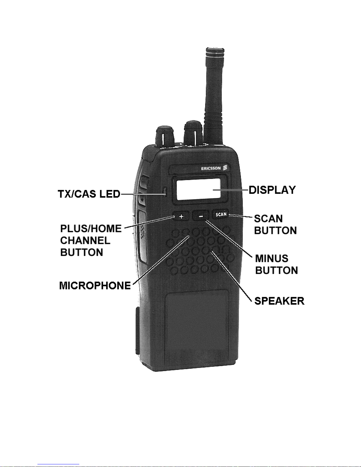
Figure 1 – KH-500 Scan Radi o
9
Page 10

Figure 2 – KH-600 System R adio
10
Page 11
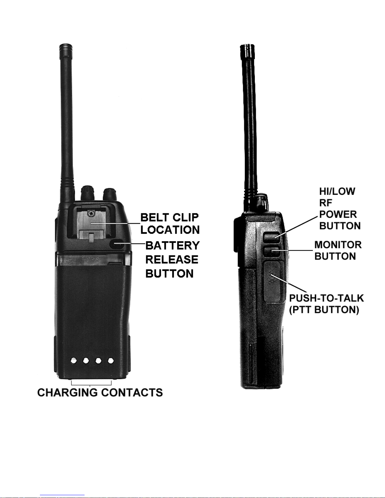
Figure 3 - Back And Left Panel Views
11
Page 12
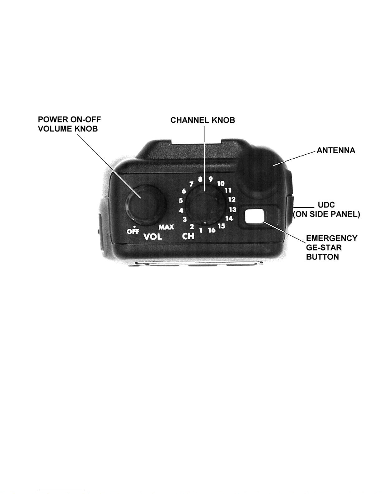
Figure 4 - Top, Back And Left Panel Views
12
Page 13

BUTTONS AND KNOBS
This section describes the primary function of the
button and knob controls. Other functions associated
with these controls are detailed in later sections.
POWER
ON-OFF/
VOLUME
KNOB
Turns radio on and off and adjusts
audio listening level.
When the radio is turned on, it will
resume operation at the last
operating state (channel, etc.) and
the power-up alert tones will be
sounded. Three (3) beeps indicate
the radio is in the normal (receive
mode); four (4) bee ps in dicat es the
radio is scanning. The operating
status of the ra dio wi ll be disp layed
in the Liquid Crystal Display (LCD)
window.
Rotating the control clockwise
increases the volume level.
13
Page 14

PUSH-TO-TALK
Pressing the PTT button on the
BUTTON (PTT)
side of the radio will key the radio
transmitter.
If the radio is not scanning, it will
transmit on the selected
(displayed) channel. If the radio is
scanning when the PTT button is
pressed, the radio may be
programmed to transmit on the
selected channel or on the current
receive scan channel if the PTT is
pressed during the scan hang time.
If the selected channel is
programmed with Type 99 Tone
Decode enabled, pressing the PTT
button once will disable Type 99
Tone Decode by switching the
radio from the Selective Call mode
to the Monitor mode. The PTT
button must be released and then
pressed a second time to key the
radio.
Page 15

MONITOR
The Monitor button has several
BUTTON
functions. Its operation will vary
depending upo n progr am min g.
When the Monitor button is
pressed and held down, all
transmissions will be heard even if
Channel Guard protected. This
permits channel monitoring before
transmitting. If the button is held for
more than one second, Channel
Guard decode will toggle ON or
OFF (if it is programmed on the
selected channel).
The Monitor button is also used to
reset the Type 99 decoder after a
Type 99 call is received. Quickly
press and release the button to
reset the Type 99 decoder to
receive the next Type 99 call.
15
Page 16

CHANNEL
A rotary switch permits selection of
SELECT
KNOB
EMERGENCY
GE-STAR
BUTTON
channels. Rotating the switch
clockwise increases the channels
and counterclockwise decreases
the channels. The channel is
visible by looking at the channel
switch from the top or viewing the
LCD display.
Pressing for at least one (1)
second will transmit the
Emergency GE-STAR code on the
selected channel or a pre-
Hi/Low
BUTTON
programmed HOME channel.
Pressing for at least one (1)
second selects the transmit power
output by togg ling from high-low or
low-high. Mus t be pre-pr ogramme d
for operation.
16
Page 17

Three (3) buttons below the LCD display are used
to control scan operations when used in conjunction
with the
button.
Toggles the scan feature on and off.
Used in conjunction with the
button to ad d channels to the s can list
or increase the channel's priority
status.
Home Channel button (if programmed
in personality)
Used in conjunction with the
button to erase the selected channel
from the scan list.
Used to decrease the level during
squelch adjus t mode.
17
Page 18

DTMF Keypad
Permits operator to make telephone
(KH-600 only)
interconnect calls on radio systems
equipped with this option.
The top row of buttons (
pre-programmed telephone
interconnect numbers (see
Telephone Interconnect Calls
section).
) provide access to up to three
,
,
18
Page 19

INDICATORS
The Liquid Crystal Display (LCD) indicates the
channel n umber. In addit ion there are s even (7) status
indicators (flags) which show scan status, Type 99
Tone Decode status, transmit High/Low power status
and Channel Guard status.
The LCD backlight ing will turn on anytime a contro l
button is pressed. It will r emain on for five (5) seconds
after the button is released. If a control button is
pressed while the backlight is on, the backlight remains
on for another five (5) seconds. Backlighting may be
programmed to remain off at all times.
SCN HI
S P1 P2
PG CG
Figure 5 - Liquid Crystal Display (LCD)
CHANNEL
The selected channel number is
displayed in the LCD window. When
12
data is written into or read from the
radio during PC programming, a P is
displayed.
19
Page 20

STATUS INDICATORS
SCN This status ind ic ator t ur ns on when the
scan function of the radio has been
enabled.
S When this indicator is o n, the selec ted
channel is a non-priority scan channel.
P1 When this indicator is o n, the selec ted
channel is a Priority 1 scan channel.
P2 When this indicator is o n, the selec ted
channel is a Priority 2 scan channel.
PG When this indicator is o n, the selec ted
channel is programmed as a paging
channel (Type 99 Decode). The
indicator will blink when the selected
channel is placed in the m onitor mode
or upon the reception of a call.
CG When this indicator is on, Channel
Guard is enabled on the selected
channel. The indicator will go out
when the se lec te d c ha nne l is place d i n
the monitor mode.
20
Page 21

HI When this indicator is o n, the selec ted
channel is enabled for transmit high
power.
TX/CAS LED Red light on steady - transmitter is
active or keye d.
Red light b link in g - lo w ba ttery v olt age ,
recharge or replace battery.
Green on steady - channel busy
indication, ra dio has detected a carrier
on selected channel.
ALERT TONES
Alert tones or "beeps" are sounded when some
buttons are pressed and when the operating status of
the radio changes. All alert tones m ay be program med
to be remain off. The v olum e level of so me a lert tones
or "beeps" can be changed by the volume control.
21
Page 22

Power-up Self-test
Each time the radio is turned on, it will perform
power-up self-test. All display segments will turn on,
and after successful completion of the test, the radio
will change to the last operating state (channel, etc.)
and sound three ( 3) or fo ur (4) beeps . Three (3) be eps
sound if the radio is operat ing in the normal (not s can)
state. Four (4) beeps will sound if the radio is
scanning. The status will be indicated in the LCD. If the
radio fails the self-test, no beeps will be sounded.
Carrier Control Timer
This feature, programmable on a per-radio basis,
prevents unnecessary channel traffic and radio
damage if the transmit timer limit is exceeded. If the
programmed ti mer times-out during a tra ns mis s ion, the
radio will bee p an d s top tr ans m itt ing. The beeping tone
will continue until the operator releases the PTT
button. Releasing the PTT button resets the timer.
22
Page 23

Channel Busy Lock-out
If channel busy lock-out has been programmed on
the selected channel, the transmit function will be
inhibited when th e oper ator press the PTT butto n whil e
the radio detects a carrier on the channel unless the
carrier is modulated with the corresponding Channel
Guard tone or code for that selected c hannel. Cha nnel
busy lock-out continues to function if Channel Guard
decode is disabled with the MONITOR button. The
channel-busy feature is programmable on a perchannel basis.
Type 99 Alert Tone
The Type 99 alert tone, indicating a receive Type
99 call, may be enabled or disabled by programming. If
the program med tone seq uence is detec ted, the radio
will beep until the second paging tone expires. If the
alert tones are disabled, no alert tones will be present
when a Type 99 call is receive d.
NOTE
The Type 99 alert tones can only be turned off by
disabling ALL alert tones.
23
Page 24

A.N.I. Alert Tone
If the A.N.I. transmission is programmed to occur
before the beginning of the conversation, an optional
Automatic Number I dentif icati on (A.N.I.) alert beep can
be enabled or disabled by programming. If the alert
tone is enabled, a beep will sound after the PTT is
pressed to indicate to the operator to begin voice
transmission. Some communication systems require a
time delay before voice transmission begins. If the alert
tone is disabled, no bee p will soun d.
Scan Alert Tone
The radio wil l sound a beep w hen the
button is
pressed.
Priority-One (P1) Scan
If the Priority 1 alert tone is enabled by
programming and the radio receives a signal on the
Priority 1 channel when scanning, the radio will so und
a beep. The P1 alert tone can be disabled without
disabling other alert tones.
24
Page 25

Radio/Channel Failure
The simultaneous flashing of the LCD display and
the sounding of beeps indicates the synthesizer is
unable to correctly lock on the selected channel. At this
time the radio changes to a mute condition and no
audio is heard from the speaker when receiving and
the transmit is inhibited if the PTT button is pressed.
Select another channel, change the battery pack or
have the radio repaired.
25
Page 26

OPERATION
RECEIVING A MESSAGE
1. Turn the radio on by rotating the
ON/OFF/VOLUME control clockwise from the "off"
detent. After the radio has successfully completed
its power-up self-test, it will begin operation at the
last operating state (channel, etc.). The operating
status of the r adio will be displayed on the LCD. If
enabled, the power-up alert tones (three or four
beeps) will be sounded.
2. Select the desired operating channel by rotating
the CHANNEL SELECT control until the desired
channel number appears on the LCD.
3. When a transmission is received (and the correct
CG/DCG or Type 99 signal is decoded, if
programmed and enabled), the receiver will
unsquelch and the message will be heard in the
speaker.
4. Adjust the volume as necessary by rotating the
ON/OFF/VOLUME control.
26
Page 27

NOTE
Pressing the MONITOR button unsquelches the
receiver for the first three ( 3) seconds the button is
held. All transmissions will be heard, even if
Channel Guar d protected. If it is held for mor e than
three (3) seconds, the Channel Guard decoder will
be toggled on or off ( if pro gram med for th e sel ected
channel).
SENDING A MESSAGE
1. Turn the radi o on and select th e desired oper ating
channel as described in
MESSAGE
.
RECEIVING A
2. Press the MONITOR button to determine if the
channel is in use or observe the TX/CAS LED
which shows green if the channel is busy.
Never
interrupt another transmission.
3. Hold the radi o so the antenna is vertica l and press
and hold the PTT button when you are ready to
transmit. Speak directly into the grill or across the
face of the radio or external microphone. Release
the PTT button when you are finished talking.
Messages can not be received and heard whe n the
PTT button is pressed.
27
Page 28

NOTE
When transmitt ing on a paging c hannel (Type 99, if
programmed), the PTT button must be pressed
twice. The first press takes the radio out of
Selective mode. The second press keys the
transmitter for normal transmitter operation.
HOME CHANNEL OPERATION
A Home Channel feature is available if programmed
into the personality. This can stand alone or be used
in conjunction with Emergency GE-STAR. If Stand
Alone Home Channel and Emergency GE-STAR with
Home Channel are selected, then the same channel
must be selected as the Home Channel.
1. Press and hold the
1-second. The channel number on the LCD will
change to identify the Home Channel. Pressing
the
considere d inadver tent, and s witch ing to t he H ome
Channel will not occ ur.
2. Within 5 seconds press another button to confirm
the Home Channel selection. If another button is
not pressed, the KH will revert to the channel
button for less than 1-second will be
button for more than
defined by the Channel Select knob. The KH will
remain on the Home Channel until the Channel
Select knob is moved to a new position.
28
Page 29

TYPE 99 OPERATION
The radio may be programmed to power up in the
Selective mod e or in the Monitor mode. If the Se lectiv e
mode is programmed and a Type 99 channel is
selected at power up, the PG status flag wil l ill uminat e.
If the Monitor mode is programmed and a Type 99
channel is selected, the PG status flag will blink.
When the radio is operating in the Selective mode,
it operates as a tone and voic e rece iver and on ly thos e
calls that are coded for it will be heard.
When the radio is op erati ng in the Monitor mod e, a ll
calls (with correct Channel Guard, if programmed) will
be heard.
In either mode, when a Type 99 channel has been
selected and a valid code is received, a series of alert
tones (if programmed) will alert the operator of the
incoming call. If the radio is in the Selective mode, it
will automatically switch to the Monitor mode after the
detection of the second Type 99 tone.
29
Page 30

NOTE
If the radio was programmed to power up in the
Selective mode, changing positions on the channel
select switch will always place a Type 99
programmed channel in the Selective mode. If the
radio was programmed to power up in the Monitor
mode, changing positions on the channel select
switch will always place a Type 99 channel in the
Monitor mode.
Type 99 Selective Call Receiving and Sending
1. Select the appropriate channel to receive the Type
99 tone signal.
2. After a Type 99 call is received and the beeps
have sounded, press the PTT button and answer
the call. When the communication sequence is
completed, press the MONITOR button to reset
the radio for the next call.
3. Whe n the radio is reset (Selec tive mode), Ty pe 99
operation can be disabled by pressing and
releasing the PTT button. The PG status flag will
blink. No transmission occurs. A second press of
the PTT button will result in a normal transmission.
30
Page 31

4. To return to Type 99 Selective mode, press the
MONITOR button. The PG status flag will be on.
SCAN OPERATION
The radio may be programmed for a front panel
selectable Priority 1 (P1) channel, a fixed preprogrammed P1 channel or a selected P1 channel. A
scan list mus t b e cr eate d be for e sc an operation c an be
used. All non-priority (S) channels and the Priority 2
(P2) channel are added or deleted from the scan list by
using
operator to modify the sc an list by us ing the
in conjunction with the
programmed and cannot be changed.
selected by the CHANNEL SELECT control.
A front panel selectable P1 channel permits the
in conjunction with
A fixed P1 channel has already been pre-
A selected P1 channel becomes the channel
Each channe l in the scan list is retained in m emory
or
and
keys.
.
button
when the radio is t ur ned off or whe n th e b atter y p ac k is
removed.
31
Page 32

Starting Or Stopping Scan
Press the
The SCN status flag will come on. To turn off the
scanning function, press the
status flag will go off.
Receiver Scan Rate
Scan rate will vary depending upon the number of
channels on the scan list and whether scanning for
Channel Guar d. Fewer channe ls on the s can lis t or n ot
scanning for Chan nel Guard will result in a fast er scan
rate.
button to turn on the scan function.
button and the SCN
There are three types of Scan condition: simple
scan, priority scan and Channel Guard scan.
When Scan function is turned on, the radio will
perform a simple scan o n all channels on the scan list
plus the channel selected by the CHANNEL SELECT
switch although that channel may not be on the scan
list. Once activity is detected (and if programmed, the
correct Channel Guard is decoded) on a channel, the
radio changes the scanni ng mode from sim ple scan to
priority sc an. The ch ann el with activ ity will be indic ated
32
Page 33

in the LCD d isplay al ong with th e correspon ding stat us
flag, S, P1 or P2.
The scan function is now in the priority scan mode
and scanning will be determined by the following
conditions:
•
•
NON-PRIORITY PROGRAMMED CHANNELS The radio will lock on the channel until activity on
the channel ceases. The scanning will resume
after a pre-programmed time delay.
PRIORITY 1, NON-PRIORITY PROGRAMMED
CHANNELS - If the rece ive channe l is non-pr iority ,
the radio will sample the Priority 1 channel for
activity. Priority 1 channel will continue to be
sampled while remaining on the non-priority
channel until the carrier ceases and scanning
resumes after a pre-programmed delay. Should
activity be detected during a sampling of the
Priority 1 channel, the radio will switch to the
Priority 1 channel and remain there until activity
ceases on the Priority 1 channel. Once activity
ceases on the Priority 1 channel, scanning will
resume after a pre-programmed delay.
33
Page 34

If the receive channel is Priority 1, the radio will
lock onto this channel for the duration of the
activity and no other channels will be scanned.
After the activity ceases, scanning will resume
after a pre-programmed delay.
•
•
PRIORITY 2, NON-PRIORITY PROGRAMMED
CHANNELS - This condition operates similar to
the above with the Priority 2 replacing the Priority 1
references.
PRIORITY 1, PRIORITY 2, NON-PRIORITY
PROGRAMMED CHANNELS - If the receive
channel is non-priority, the radio will sample the
Priority 1, return to the non-priority channel, then
sample the Priority 2 channel. This sampling will
continue until activity ceases on the non-priority
channel or activity is detected on either of the
Priority channels. If activity is detected on the
Priority 2 channel, the radio will lock onto that
channel but will continue to sample the Priority 1
channel f or activity. Shou ld activity be detected on
the Priori ty 1 cha nnel wh ile l ocked o nto t he Prior ity
2 channel, the radio will switch to the Priority 1
channel and remain there for the duration. After
activity ceases, scanning will resume after a preprogrammed delay.
34
Page 35

If activity is detected on the Priority 2 channel
instead of Priority 1 or a non-priority channel, the
radio will s ample the Pr iority 1 channe l for activ ity.
The radio will remain locked onto the Priority 2
channel for the duration of the activity unless the
sampling of the Priority 1 channel detects activity.
If this occurs, the radio will lock onto the Priority 1
channel for the duration of the activity. Scanning
will resume after a pre-programmed time delay.
If activity is detected on the Priority 1 channel
instead of Priority 2 or a non-priority channel, the
radio will lock onto the Priority 1 channel for the
duration of the activity. Scanning will resume after
a pre-programmed delay.
35
Page 36

Adding Channels To Scan List
1. Scan must be off to add channels to the scan list.
If the SCN status flag is on, press the
turn scan off.
2. Select the desired channel with the CHANNEL
SELECT control.
3. Press and ho ld the
press the
flag appears : S for non-priority, P2 for Priority 2 or
P1 for Priority 1.
key until the desired Priority status
button an d then repeat edly
NOTE
button to
Priority 1 can only be selecte d by th e operat or if t he
radio is pr ogramm ed for front pa nel selec tabl e sc an
option.
4. If a new Priority 1 or Priority 2 channel is selected,
the previously corresponding priority channel will
become a non-priority scan channel.
36
Page 37

Deleting Channels From Scan List
1. Scan must be off to delete channels from the scan
list. If the SCN status flag is on, press the
button to turn scan off.
2. Select the desired channel with the CHANNEL
SELECT control.
3. Press and hold the
scan list.
Priority 1 c an only be delete d by the oper ator if the
button to delete the selec ted channel fro m the
button and then press the
NOTE
radio is programmed for front panel selectable P1
channel option.
37
Page 38

Using The Radio With Scan
The Selected Channel
The selected channel is the channel in the display
when scan is turned on by the
button. The
selected channel does not necessarily have to be a
channel on the scan list. When a signal is not being
received, the radio reverts to this channel for
transmitt in g. Whe n a signal is be ing r ec eived, the r ad io
can be pre-progra mm ed to either rever t to t his sel ec ted
channel or remain on the receive channel for
transmissions.
If the radio was pre- pr ogram me d for transm it o n th e
selected channel, the selected channel will be
displayed on the LCD when the transmitter is keyed.
If the radio was pre- pr ogram me d for transm it o n th e
receive channel, the channel will be displayed on the
LCD and the transmitter will transmit on that channel
providing this is accomplished during the preprogrammed time delay before scanning resumes.
38
Page 39

Should the operator change the channel with the
CHANNEL SELECT control during scanning, the new
channel will become the selected channel. If the
selected channel is changed to a channel not in the
scan list, the new c hannel will be temporarily added to
the scan list until the selected channel is changed
again or scan function is turned off.
Scanning With Channel Guard
Any channel in the scan list can be scanned not
only for activity but for correc t Channel Gu ard tones or
DCG codewords. The correct tone or codeword will
permit scann ing to lock onto that channel w ith activity.
If the radio detects activ ity but without th e correct tone
or code, the green BUSY LED will light but no audio
will be heard from the speaker.
39
Page 40

TELEPHONE INTERCONNECT CALLS
(KH-600 ONLY)
The operator may make telephone interconnect
calls on radio systems equipped for this option. One of
three pre-programmed numbers can be selected and
dialed automatically using either of the three keys on
the top row of the DTMF keypad. The telephone
numbers may also be manually dialed using the
keypad.
Communication takes place in a simplex mode. In
other words, you cannot talk and listen at the same
time. You must press and hold the PTT button each
time you wish to talk (transmit) and release it when you
wish to listen (receive).
40
Page 41

Specific procedures for placing a telephone
interconnect call from the radio are determined by the
radio system and the individual radio programming.
Consult your radio dealer for the exact operating
procedures necessary for your system and radio.
Pre-programmed Number
1. Select the channel in your radio system that has
telephone interconnect capability using the
CHANNEL SELECT control.
2. Press and hold the PTT button and momentarily
press the
3. While still holding the PTT button, momentarily
depress one of the keys (
the desired pre-programmed number.
4. Release the PTT button. The microphone will be
muted and the DTMF tones will be heard in the
speaker as the radio sends the selected number.
5. When the called party answers, press the PTT
button each time you wish to speak (transm it) and
release it each time you wish to listen (receive).
button to activate the auto-dialer.
, ,
) to select
41
Page 42

6.
At the completion of the call, press and hold the
PTT button and then press the appropriate DTMF
buttons to se nd t he disconnect ton e( s ) and r e mov e
the radio from the telephone interconnect function.
NOTE
Consult with the radio dealer for the procedure to
disconnect a telephone interconnect call from the
system.
42
Page 43

Placing A Manually Dialed Call
1. Select a channel in your radio system that has
telephone interconnect capability by using the
CHANNEL SELECT control.
2. Pres s and hold t he PTT button and then press th e
DTMF buttons (as required by the radio system) to
originate a telephone interconnect call. The radio
will transmit the selected tone.
3. Release the PTT button and listen for a dial tone.
4. Press and hold the PTT button and then dial the
desired telephone number using the numeric
keypad. As each number is dialed, th e DTMF tone
will be heard in the speaker.
5. Release the PTT button w hen the di al sequenc e is
complete.
6. When the called party answers, press and hold the
PTT button each tim e you wish to spe ak (transmit)
and release it each time you wish to listen
(receive).
7. At the completion of the call, press and hold the
PTT button and then press either the DTMF
buttons (as required by the radio system) to
disconnect from the telephone interconnect
function.
43
Page 44

EMERGENCY OPERATION
If enabled by pre-programming, GE-STAR
emergency signaling can be transmitted when the
Emergency button is pressed and held f or one s econ d.
This Emergency GE-STAR ID can be pr e-program med
to be sent on the channel selected by the CHANNEL
SELECT c ontrol or a pre-progr ammed Home C hannel.
The red TX indicator will light and the radio proceeds
to transmit the Emergency GE-STAR ID for the
programmed time interval and number of times (1 to 15
or unlimited, pre-programmed). If programmed for
unlimited times, the emergency operation will continue
until the batter y is dea d or the rad io is turn ed OFF a nd
then back ON.
Should the Emergency GE-STAR button be
pressed when the radio is in scanning operation, the
radio will stop scanning, perform the transmission of
the GE-STAR ID emergency signaling and then
resume normal operation.
The emergenc y state can be c leared by turning th e
radio off and then back on.
44
Page 45

BATTERY INFORMATION
CHARGE BEFORE USING
Insert the radio into the slot on the charger and
ensure that the ON/OFF/VOLUME control is in the
OFF position. Connect charger to a 120 VAC outlet.
An optional 230 VAC charger may be needed for
international applications. Charge the battery for the
first time a t l east 14 hours but no lon ger th an 48 h ours .
Over-charging may reduce battery life.
RECHARGING THE BATTERY
Recharge the battery when you experience difficulty
in receiving or sending a message. Also the battery
may need recharging when the red TX indicator is
blinking.
Chargers are available with nominal charge times
of one to 14 hours. Combinations include single and
multiposition chargers. When charging a battery pack
that is attached to a radio, always turn the radio OFF to
ensure a full charge. For s pecific ins tructions, ref er the
applicable charger Operator's Manual. Charging in
non-Ericsson equipment may lead to battery damage
and void the battery warranty.
45
Page 46

CONDITIONING THE BATTERY
Batteries which have been stored (charged or
discharged) will generally not be capable of full
capacity until the batteries have been fully cycled two
or three times. (Charging the battery in an Ericsson
rapid charger and then discharging the battery pack
with the radio until low battery is indicated is
considered one cycle.)
INSTALLING THE BATTERY PACK
1. Ensure the ON/OFF/VOLUME control knob is in
the OFF (detent) position.
2. Align the battery pack tabs with the battery
mounting plate slots on the back of the radio (see
Figure 6).
3. Insert the tabs into the slots, push down and slide
the battery to war d t he batt er y latc h unt il the batter y
latch clicks into place.
46
Page 47

Figure 6 - Installing And Removing The Battery Pack
REMOVING THE BATTERY PACK
1. Ensure the ON/OFF/VOLUME control know is in
the OFF (detent) position.
2. Press the battery release button to release the
battery.
3. Remove the battery pack by sliding it back until it
stops. Then l ift up and a way unti l it separa tes from
the radio.
47
Page 48

BATTERY CARE & MAINTENANCE
•
•
•
•
•
Your char ger is int ended for indoor use onl y. Keep
the charger and/or wal l cube dry . Do Not use in or
near water.
Never let the battery contacts touch metal objects
that could short-circuit the contacts. For example,
keys or coins in your pocket.
Do Not disassemble a battery.
Do Not dispose of a battery in a fire.
Use only the supplied or specified battery and
charger.
•
BATTERY RECYCLING
state and local laws , it may be illegal to disp ose of this
battery into the municipal waste stream. Check with
your local solid waste officials for details in your area
for recycling options or proper disposal. Call Toll Free
1-800-8-BATTERY for information and/or procedures
Periodically condition your battery for improved
battery capacity and performance.
The product that you have purchased
contains a rechargeable, recyclable battery.
At the end of its useful life, under various
for returning rechargeable batteries in your state.
48
Page 49

OPERATING TIPS
Antenna location and condition is important when
operating a portable radio. Operating the radio in low
areas or terrain, und er power lines or brid ges, insid e of
a vehicle or in a metal or steel framed building can
severely reduce the range of the unit. Mountains and
buildings can also reduce the range of the unit.
In areas where transmission or reception is poor,
some improvement may be obtained by ensuring that
the antenna is vertical. Moving a few yards in another
direction or moving to a higher elevation may also
improve communications. Vehicular operation can be
aided with the use of an externally mounted antenna.
Battery condition is another important factor in the
trouble free operation of a portable radio. Always
properly charge the batteries.
49
Page 50

EFFICIENT RADIO OPERATION
Hold the portable radio approximately three inches
from your mouth and speak into the microphone at a
normal voice level.
Keep the antenna in a vertical position when
receiving or transmitting a message.
Do not hold the ant enna whe n rece iving a mes sage
and, especially, do not hold when transmitting a
message.
ANTENNA CARE AND REPLACEMENT
Do not use the portable radio with a damaged or
missing antenna. A minor burn may result if a
damaged antenna comes into contact with the skin.
Replace a damaged antenna immediately. A missing
antenna could damage your portable radio.
Use only the supplied or approved antenna.
Unauthorized antennas, modifications or attachments
could damage the radio unit and may violate FCC
regulations.
50
Page 51

ELECTRONIC DEVICES
RF energy from your portable radio may affect
some electronic equipment. Most modern electronic
equipment in cars, hospitals, homes, etc. are shielded
from RF energy. Howev er, in areas that instruct you to
turn off two-way radio equipment, always observe the
rules. If in doubt, turn it off.
AIRCRAFT
Always turn off your portable radio before boarding
any aircraft.
•
•
Use it on the ground only with crew permission
Do not use it in the air
BLASTING AREAS
To avoid interfering with blasting operations, turn
your radio OFF when in a "blasting area" or in areas
posted "turn off two-way radio". Remote control RF
devices are us ed by s o me construction c rews to s et off
explosives .
51
Page 52

POTENTIALL Y EX PLO SI VE ATMOS PH ER ES
Areas with potentially explosive atmosphere are
often, but not always, clearly marked. These may be
fueling areas, such as gas stations, fuel or chemical
transfer or storage facilities, and areas where the air
contains chemicals or particles, such as grain, dust or
metal powders.
Sparks in such areas could cause an explosion or
fire resulting in bodily injury or even death.
Turn OFF your radio when in any area with a
potentially explosive atmosphere. It is ra re, but not
impossible that the radio or its accessories could
generate sparks.
52
Page 53

ACCESSORIES
The following ac cess ories are ava ilabl e for us e with
the KH-500/600 radio units:
Antenna, 136-155 MHz, Helical KRE 101 1219/1
Antenna, 150-165 MHz, Helical KRE 101 1219/2
Antenna, 160-174 MHz, Helical KRE 101 1219/3
Antenna, 403-440 MHz, Helical KRE 101 1219/10
Antenna, 440-470 MHz, Helical KRE 101 1219/12
Antenna, 470-512 MHz, Helical KRE 101 1219/13
Antenna, 403-440 MHz, Whip KRE 101 1223/10
Antenna, 440-512 MHz, Whip KRE 101 1223/12
Rechargeable Batt ery Pack
(Extra High Capacity )
Rechargeable Batt ery Pack
(High Capacity)
Speaker/Microphone
(Ericss on Label)
Earpiece RLD 541 07/11
Rapid Charger, 120/230 VAC
(Ericss on Label)
Multi-Rapid Charger, 120/230 VAC
BKB 191 202
BKB 191 203
KRY 101 1617/33
BML 161 51/505
BML 161 51/513
(Ericss on Label)
53
Page 54

ACCESSORIES CONTINUED
Compact Rapid Charger, 120/230 VAC
BML 161 74/12
(Ericss on Label)
International Pl ug Adapt er Kit
BML 161 74/21
(For use with BML 161 74/12 only)
Belt Clip KRY 101 1232/2
Belt Loop with Swivel Mount KRY 101 1609/A1
Leather Case w/Belt Loop KRY 101 1622/1
Leather Case w/ Belt Loop & swivel KRY 101 1622/A2
Shoulder Strap
KRY 101 1607/1
(For Leather Case)
54
Page 55

INTRINSICALLY SAFE USAGE
Selected portable radios with appropriate factory
installed options are certified as Intrinsically Safe by
the Factory Mutual Research Corporation and the
Canadian Standards Association. Intrinsically Safe
approval through Factory Mutual includes Class I, II,
III, Division 1 hazardous locations in the presence of
Groups C, D, E, F and G atm ospheres. Non-I ncendive
approval includes Class I, Division 2 hazardous
locations in the presence of Groups A, B, C and D
atmospheres. Approval through the Canadian
Standards Association (CSA) includes Class I Groups
C and D, Class II Group G Coal Dust; and Class III.
CSA approv al also incl udes Class I, D ivision 2 Groups
A, B, C and D.
Hazardous locations are defined in the National
Electrical Code. Useful standards NFPA 437A and
NFPA 437M for the classifications of hazardous areas
can be ordered from the National Fire Protection
Association, Batterymarch Park, Quincy, MA 02269.
55
Page 56

BATTERY PACKS
Only battery packs identified with a green FM/CSA
label shall be used with a portable radio that is rated
and labeled as Factory Mutual/CSA Intrinsically Safe.
Use of nonspecified battery packs voids Factory
Mutual/CSA approval. The following battery packs are
approved for use in intrinsically safe radios:
BKB 191 202/2 Rechargeable Battery Pack,
Extra High Capacity
BKB 191 203/2 Rechargeable Battery Pack,
High Capacity
56
Page 57

ACCESSORIES
Use of accessories other than those listed voids
Factory Mutual/CSA approval. The following
accessories are for use with intrinsically safe radios:
Speaker/Microphone/Antenna
(Ericss on Label)
Earpiece Kit RLD 541 07/11
Antenna, 136-155 MHz, Helical KRE 101 1219/1
Antenna, 150-165 MHz, Helical KRE 101 1219/2
Antenna, 160-174 MHz, Helical KRE 101 1219/3
Antenna, 403-440 MHz, Helical KRE 101 1219/10
Antenna, 440-470 MHz, Helical KRE 101 1219/12
Antenna, 470-512 MHz, Helical KRE 101 1219/13
Antenna, 403-440 MHz, Whip KRE 101 1223/10
KRY 101 1617/31
Antenna, 440-512 MHz, Whip KRE 101 1223/12
Belt Clip KRY 101 1232/2
Belt Loop w/swivel KRY 101 1609/A1
Leather Case w/Belt Loop KRY 101 1622/1
Leather Case w/ Belt Loop & swivel KRY 101 1622/A2
Shoulder Strap
(for leather cas e)
KRY 101 1607/1
57
Page 58

GLOSSARY
conventional
channel
- a radio channel (transmit/receive) that is
allocated for conventional (non-trunked) use
and may be manually selected by the
operator.
conventional mode - communicating on radio channels allocated
for conventional use.
CCT - Carrier Controlled Timer - a programmable
timer that will disable a transmission if the
timer length is exceeded.
CG - Channel Guard - a method of controlling
receiver mute wit h a tone or digital code.
Talk-around mode - also referred to as "direct mode", talk-
around provides a direct unit-to-unit short
Telephone
Interconnect
range communications li nk. It is intended t o
maintain communications outside of the
main system coverage area.
- this f eature allows the user to initi ate or
receive telephone calls through the radio if
the system is configured for this operation.
(Trunked Mode Only)
58
Page 59

Channel
TX Freq
Encode
RX Freq
Decode
USE
Number
1
2
3
4
5
6
7
8
9
(MHz)
CG/DCG
(MHz)
CG/DCG
10
11
12
13
14
15
16
59
Page 60

NOTES
60
Page 61

WARRANTY
A Ericsson Inc. (hereinafter "Seller") warrants to the original purchaser for use (hereinafter "Buyer") that
necessary repaired or replacement parts. Any repaired or replacement part furnished hereunder shall be
defects in or nonconformity of the Equipment, whether the claim is in contract, warranty, tort (including
THE SELLER BE LIABLE FOR ANY INCIDENTAL, CONSEQUENTIAL, SPECIAL, INDIRECT OR
Equipment manufactured by Seller shall be free from defects in material, workmanship and title, and shall
conform to its published specifications. With respect to any Equipment not manufactured by Seller (except for
integral parts of Seller's Equipment to which the warranties set forth above shall apply). Seller gives no
warranty, and only the warranty, if any, given by the manufacturer shall apply. Batteries are excluded from this
warranty but are war ranted under a separate Ni ckel-Cadmium B attery Warranty.
B. Sel l er's obli gat i ons set forth in P a ragraph C below shall apply only t o failures to meet the above warranties
(except as to title) occurring within the following periods of time from date of sale to the Buyer and are
conditioned on Buyer's giving written not i ce t o Seller within t hi rty (30) days of such occurrenc e:
1. for fuses, incande sc ent lamps, vacuum tubes and non- rechargeable batteri es, operable on arrival only.
2. for parts and accessories (except as noted in B.1) sold by Seller's Service Parts Operation, ninety (90)
days.
3. for all ot her Equipment of Seller's manufacture, one (1) year.
C. If any Equipment fails to meet the foregoing warranties, Seller shall correct the failure at its option (i) by
repairing any defective or damaged part or parts thereof, or (ii) by making available at Seller's factory any
warranted for the remainder of the warranty period of the Equipment in which it is installed. Where s uch failure
cannot be corrected by Seller's reasonable efforts, the parties will negotiate an equitable adjustment in price.
Labor to perform warranty service will be provided at no charge during the warranty period only for the
Equipment covered under Paragraph B.3. To be eligible for no-charge labor, service must be performed by an
Authorized Service Center or other Servicer approved for these purposes either at its place of business during
normal business hours, for mobile or personal equipment, or at the Buyer's location, for fixed location
equipment. Service on fixed location equipment more than thirty (30) miles from the Service Center or other
approved Servicer's place of busines s will include a charge f or trans port ation.
D. Seller's obligations under Paragraph C shall not apply to any Equipment, or part thereof, which (i) has
been modified or otherwise altered other than pursuant to Seller's written instructions or written approval or, (ii)
is normally consumed in operation or, (iii) has a normal life inherently shorter than the warranty periods
specified in Paragraph B, or (iv) is not properly stored, installed, used, maintained or repaired, or, (v) has been
subjected to any other kind of m i suse or detrim ental exposure, or has bee n i nvolved in an accident.
E. The preceding paragraphs set forth the exclusive remedies for claims (except as to title) based upon
negligence), strict liability or otherwise, and however instituted. Upon the expiration of the warranty period, all
such liability shall terminate. The foregoing warranties are exclusive and in lieu of all other warranties, whether
oral, written, expressed, implied or statutory. NO IMPLIED OR STATUTORY WARRANTIES OF
MERCHANTABILITY OR FITNESS FOR PARTICULAR PURPOSE SHALL APPLY. IN NO EVENT SHALL
EXEMPLARY DAMAGES.
This warranty applies only within the Unit ed States.
ECX-886A (1/95)
Page 62

NICKEL-CADMIUM BATTERY WARRANTY
A. Ericsson Inc. (hereinafter "Seller") warrants to the original purchaser for use
(hereinafter "Buyer") that nickel-cadmium batteries supplied by Seller shall be free from
defects in material and workmanship, and shall conform to its published specifications for a
period of twelve (12) months from the date of purchase.
B. For purposes of this warranty, batteries shall be deemed defective if (1) the battery
capacity is less than 80% of rated capacity, or (2) the battery develops leakage.
C. If any battery fails to meet the foregoing warranty, Seller shall correct the failure by
issuing a replacement battery upon receipt of the defective battery at an Authorized Service
Center (ASC). To obtain the name and address of a ASC, ask your salesperson, consult
the Yellow Pages, or call the number printed at the bottom of this page.
D. Replacement batteries shall be warranted only for the remaining unexpired warranty
period of the original battery. This warranty becomes void if:
(1) The battery has been subjected to any kind of misuse, detrimental exposure, or has
been involved in an accident.
62
Page 63

OPERATOR'S RADIO SETUP
RADIO TYPE:
FREQUENCY BAND:
OPERATOR'S NAME:
EMERGENCY HOME CHANNEL:
HOME CHANNEL:
63
Page 64

EMERGENCY NUMBERS
Police
State Police
Fire
Poison Control
Ambulance
Life Saving and
Rescue Squad
Ericsson Inc.
Private Radio Systems
Mountain View Road
Lynchburg,Virgi ni a 24502 AE/LZT 123 4750/1 R1A
1-800-528-7711 (Outside USA, 804-592-7711) Printed in U.S.A.
 Loading...