

Page 1

1/153 22-FGC 101 0239/2 Uen Rev J
EDA 2530 Commissioning Procedure fo
r
Cable and Wireless Access
EDA 2530 R4.21 GA EC2
Commissioning Instructions
Page 2

EDA 2530 Commissioning Procedure for Cable and Wireless Access
1/153 22-FGC 101 0239/2 Uen Rev J 2010-04-01
© Ericsson AB 2010
Commercial in confidence
2 (200)
Copyright
© Ericsson Limited 2006 - 2010 – All Rights Reserved
Disclaimer
No part may be reproduced, disclosed or used except as authorised by contract or
other written permission. The copyright and the foregoing restriction on reproduction
and use extend to all media in which the information may be embodied.
The information in this work is the property of Ericsson Limited. Except as
specifically authorised in writing by Ericsson Limited, the receiver of this work shall
keep the information contained herein confidential and shall protect the same in
whole or in part from disclosure and dissemination to third parties. Disclosure and
disseminations to the receiver's employees shall only be made on a strict need to
know basis. The information in this work is subject to change without notice and
Ericsson Limited assumes no responsibility for factual inaccuracies or typographical
errors.
Ericsson Limited has used all reasonable endeavours to make sure that the
information contained in this work is accurate at the release date but reserves the
right to make changes, in good faith, to such information from time to time.
Trademarks
Ericsson and the Ericsson logo are trademarks of Telefonaktiebolaget LM Ericsson.
Acrobat(R) Reader copyright (C) 1987-1996 Adobe Systems Incorporated, - All
rights reserved. Adobe and Acrobat are trademarks of Adobe Systems Incorporated.
All trademarks and registered trademarks mentioned in a document of this collection
are the property of their respective holders.
Page 3

EDA 2530 Commissioning Procedure for Cable and Wireless Access
1/153 22-FGC 101 0239/2 Uen Rev J 2010-04-01
© Ericsson AB 2010
Commercial in confidence
3 (200)
Contents
1
Introduction............................................................................................ 7
1.1 Objective.................................................................................................. 7
1.2 Scope ...................................................................................................... 7
1.3 Safety Procedures ................................................................................... 7
1.4 Static Sensitive Device Handling Precautions......................................... 8
1.5 Optical Device Precautions ..................................................................... 8
1.6 Inspection/Cleaning Procedure For Optical Connectors.......................... 8
1.7 Commissioning Test Records.................................................................. 8
1.8 Required Information For Commissioning ............................................... 9
1.9 Documentation Change Request ............................................................ 9
2 EDA 2530 MSAN Equipment...............................................................11
2.1 General Equipment Description............................................................. 11
2.2 Equipment Overview ............................................................................. 11
2.3 Rack And Subrack Description.............................................................. 14
2.3.1 Rack ...................................................................................................... 14
2.3.2 EDA 2530 Subrack ................................................................................ 14
2.4 Subrack Composition ............................................................................ 15
2.4.1 Composition Rules ................................................................................ 15
2.4.2 EDA2530E Standard Configuration for CWA Parent and Stand Alone
Shelf ...................................................................................................... 16
2.4.3 Network Interface Units .........................................................................18
2.4.4 Subscriber Interface Units ..................................................................... 20
2.4.5 Subrack Connection Units ..................................................................... 23
2.4.6 Fan Tray (151-2984/02)......................................................................... 32
3 Resources ............................................................................................33
3.1 Documentation ...................................................................................... 33
3.2 Tools......................................................................................................33
3.3 Test Equipment ..................................................................................... 33
3.3.1 PC Connection Cables for Commissioning............................................ 34
3.4 Test Cables ........................................................................................... 35
3.4.1 RS232 Serial Cable Set (151-2502/01) ................................................. 36
3.5 Local Craft Terminal (LCT) Installation.................................................. 37
3.5.1 Removal of Old Issue of EDA Hub Software ......................................... 37
3.5.2 Installation of Local Operator Software on P.C...................................... 37
3.5.3 Install Application Software From CD ROM........................................... 38
3.5.4 LCT 07.02.05 – Known Issue with Java Version 1.6 ............................. 39
4 Commissioning Requirements........................................................... 41
4.1 Description Of Testing Activities............................................................ 41
4.2 Test Records ......................................................................................... 41
4.3 Preliminary Checks................................................................................ 41
4.3.1 Equipment Positioning........................................................................... 41
4.3.2 Card Equipping...................................................................................... 41
4.3.3 Cabling .................................................................................................. 42
4.3.4 Power Supply and Grounding Connections........................................... 43
4.4 Earthing And D.C. Supply Checks......................................................... 44
4.5 Power Supply Connection Unit Check................................................... 45
Page 4

EDA 2530 Commissioning Procedure for Cable and Wireless Access
1/153 22-FGC 101 0239/2 Uen Rev J 2010-04-01
© Ericsson AB 2010
Commercial in confidence
4 (200)
4.5.1 Labelling.................................................................................................45
5 Initial Configuration .............................................................................47
5.1 IP Address Configuration Of PC Used As LCT ......................................47
5.2 Common Part Card CF Download..........................................................50
5.3 Subrack Equipping .................................................................................53
5.4 Logon to The EDA 2530 Via LCT...........................................................54
5.5 Reset The Backplane EPROM...............................................................55
5.6 Software Inventory Check ......................................................................57
6 Software Download/Upgrade ..............................................................61
7 Configure IP and Ethernet Management............................................67
7.1 Configure The Optical SFP Modules Gigabit Ethernet...........................69
7.2 Configure CP Ethernet Interfaces ..........................................................72
7.2.1 Configure CP Port 1 ...............................................................................72
7.2.2 Configure CP Port 2 ...............................................................................73
7.2.3 Configure CP Port 3 (If required)............................................................73
7.2.4 Configure CP Port 4 (If required)............................................................73
7.3 Configure EDA 2530 Tag Protocol ID/Bridging Parameters...................74
7.4 ADSL Card Configuration Files ..............................................................75
7.5 SHDSL Card Configuration Files............................................................75
7.6 Configure Static VLANs..........................................................................76
7.7 Adding Interfaces to the Static VLANs ...................................................79
7.7.1 Create S-VLANs for Additional ADSL Cards (If required) ......................81
7.7.2 Create S-VLANs for SHDSL Cards (If required) ....................................83
7.7.3 Create S-VLANs for POTS Cards (If required).......................................85
7.7.4 Complete VLAN Creation.......................................................................88
7.7.5 Create S-VLANs on the “Parent” to Subtend Child#2 (If required).........88
7.7.6 Create S-VLANs on the “Parent” to Subtend Child#3 (If required).........94
7.8 Configuring The IBM Sub-Interface........................................................96
7.9 Assign The IBM IP Address ...................................................................98
7.10 Configure The Default Gateway...........................................................100
7.11 xDSL Bridge Management - Configure xDSL Bridge ...........................101
7.12 xDSL Bridge Management - Configure PVC ........................................104
7.12.1 Download xDSL PVC Management File ..............................................104
7.12.2 Check PVC Management PPPoA Payload & MRU Settings................105
7.12.3 Configure PVC Management ...............................................................106
7.12.4 Configure Additional xDSL Cards.........................................................111
7.13 xDSL Bridge Management – Downstream Flow Assignment...............112
7.14 Configure ADSL Profiles ......................................................................114
7.15 Configure SHDSL Line Profiles............................................................116
7.16 Configure SHDSL Stack Profiles..........................................................118
7.17 Configure POTS Card(s) ......................................................................121
7.17.1 POTS Card Configuration Files............................................................121
7.17.2 Step 1: LCT 07.02.05 – Known Issue with Java Version 1.6 ...............121
7.17.3 Step 2: Add POTS Card(s) Interfaces to Static VLANs........................121
7.17.4 Step 3: Configure UK National Mapping ..............................................122
7.17.5 Step 4: Configure ITAM For Double Play .............................................124
7.17.6 Step 5: Configure RTP Profiles ............................................................126
7.17.7 Step 6: Check TOIP Profiles ................................................................130
7.17.8 Step 7: Configure POTS Cards ............................................................131
Page 5

EDA 2530 Commissioning Procedure for Cable and Wireless Access
1/153 22-FGC 101 0239/2 Uen Rev J 2010-04-01
© Ericsson AB 2010
Commercial in confidence
5 (200)
7.17.9 Step 8: Build Voice Configuration........................................................ 135
8 EDA 2530 Equipment Test and Alarm Checks................................147
8.1 Equipment Test ................................................................................... 147
8.1.1 Optical Launch Power Test ................................................................. 147
8.1.2 Unit Status Check................................................................................ 147
8.2 Alarm Checks ......................................................................................148
8.2.1 Common Part Alarm Check ................................................................. 148
8.2.2 Power Supply Alarm Check ................................................................. 148
8.2.3 FAN Unit Extraction/Insertion .............................................................. 149
8.2.4 64 x ADSL2+ Unit Extraction/Insertion ................................................ 150
8.2.5 32 x SHDSL Unit Extraction/Insertion.................................................. 150
8.2.6 64 x POTS/VoIP Unit Extraction/Insertion ........................................... 151
8.3 Set Equipment Time and Date ............................................................ 152
9 Test ADSL2+, POTS, SHDSL & Connection Units.......................... 153
9.1 Configure/Activate/Test 64 Port Adsl2+ Units ..................................... 153
9.1.1 Check 64 x ADSL Cards for ADSL2 + Configuration........................... 153
9.1.2 Configure 64 x ADSL Card for ADSL2 + Configuration Profile............ 155
9.1.3 Test 64 x ADSL2+ Card....................................................................... 161
9.2 Configure/Activate/Test 32 Port SHDSL Units..................................... 163
9.2.1 Configure 32 x SHDSL Card Profiles .................................................. 163
9.2.2 Test 32 x SHDSL Cards ......................................................................168
9.3 Test 64 x POTS/VoIP Cards................................................................ 170
9.3.1 Test 64 x POTS/VoIP Cards................................................................ 170
9.4 Test iTAM Splitter Connection Unit...................................................... 172
9.4.1 Check Test Relay Switching Correctly................................................. 172
9.4.2 Configure ITAM Splitter Unit from LCT ................................................ 174
9.4.3 Continuity Testing LLUT (Line) to LLUL (POTS) Blocks...................... 177
9.5 End Of Stand Alone Configuration/Testing.......................................... 177
10 Appendix - Common Part Unit DIP Setting .....................................179
11 Test Records...................................................................................... 181
11.1 Test Record Procedure ....................................................................... 181
11.2 Certification Of Tests ........................................................................... 184
12 Glossary Of Terms ............................................................................ 187
13 References .........................................................................................191
14 Change Information........................................................................... 193
Page 6

EDA 2530 Commissioning Procedure for Cable and Wireless Access
1/153 22-FGC 101 0239/2 Uen Rev J 2010-04-01
© Ericsson AB 2010
Commercial in confidence
6 (200)
This page intentionally blank to facilitate double sided printing.
Page 7

EDA 2530 Commissioning Procedure for Cable and Wireless Access
1/153 22-FGC 101 0239/2 Uen Rev J 2010-04-01
© Ericsson AB 2010
Commercial in confidence
7 (200)
1 Introduction
1.1 Objective
The objective of this document is to detail the procedures for commissioning of the
EDA 2530 when used in the Cable and Wireless Access network.
1.2 Scope
This document will be used to commission the EDA 2530 DLE Node on site.
The DLE IP DSLAM EDA 2530 (EDA 0x0x) shelf can be equipped with up to ten 64
x ADSL2+ Cards and ten 64 x POTS/VoIP Cards and up to four 32 x SHDSL Cards
as required. The 64 x POTS/VoIP Card will be configured for H.248 protocol. The
ADSL2+, POTS/VoIP Cards and 32 x SHDSL Cards VLANs will be routed to the
GigaBit Ethernet Port of the EDA 2530 CP-IP Card. The Common Part “Backhaul”
GigaBit Ethernet Port will be connected to the IP network.
The tests in the document are to prove the functionality of the EDA 2530. These
tests will include the set-up and connection of the Local Controller, the loading of
site specific Database and the setting up of circuits through the EDA 2530.
Engineers MUST familiarise themselves with the procedure and be aware of and
observe all safety precautions BEFORE starting the commissioning procedure.
1.3 Safety Procedures
All procedures should be carried out in accordance with the Safety Rules and Safety
Notices as stated in the product handbook.
Page 8

EDA 2530 Commissioning Procedure for Cable and Wireless Access
1/153 22-FGC 101 0239/2 Uen Rev J 2010-04-01
© Ericsson AB 2010
Commercial in confidence
8 (200)
1.4 Static Sensitive Device Handling Precautions
Equipment referred to in this document contain static sensitive devices and
therefore an ESP wrist strap MUST be worn and connected to an ESP bonding point
at all times when handling slide-in-units and socketed devices (PROMS).
1.5 Optical Device Precautions
The EDA Subrack may be equipped with Optical Common Part Units containing
laser transmitters. Never look into a laser transmitter port or into a fibre optic cable.
1.6 Inspection/Cleaning Procedure For Optical Connectors
All optical fibre connectors will require inspection for damage and cleanliness.
1.7 Commissioning Test Records
The commissioning test records at the end of this document must be completed as
the commissioning progresses. A complete set of Test Records must be completed
for each EDA 2530 being commissioned. This should be retained on site for the
customer’s use if requested. Any items outstanding after the acceptance testing is
complete are to be listed in the Outstanding Items Summary at the end of this
document.
When all acceptance testing has been completed successfully, both the Ericsson
and Customer’s representatives must complete the Customer Acceptance Form at
the end of this document. If the Customer’s representative is not present on site
enter N/A (Not Available) for the Customer representative.
Page 9

EDA 2530 Commissioning Procedure for Cable and Wireless Access
1/153 22-FGC 101 0239/2 Uen Rev J 2010-04-01
© Ericsson AB 2010
Commercial in confidence
9 (200)
1.8 Required Information For Commissioning
The Customer Network Planning Authority shall be responsible for providing the
following information before commissioning can commence.
a. Unit type and location of cards in the subrack.
b. IP over Ethernet Addresses of each EDA 2530 (DLE Node Address).
c. Site/slot specific IP addresses for POTS cards.
d. IP address of the NTP Server.
e. If available, fibre loss figures for the sub-network under test.
f. The SID document, which specifies Configuration information i.e. Site
location, Floor Plan, Rack Layout, Fuse allocations, MDF block locations for
the EDA 2530 Subrack equipment, and Cable Running Out Lists.
g. Alarm Profile list for each unit type that is to be commissioned in the
subrack.
1.9 Documentation Change Request
In order to allow changes to this document to be implemented quickly, site
engineers are requested to use the Document Change Request Form at the end of
this document. The form should be sent by post, fax or e-mail to the author of this
document for the change request to be considered.
End of section
Page 10

EDA 2530 Commissioning Procedure for Cable and Wireless Access
1/153 22-FGC 101 0239/2 Uen Rev J 2010-04-01
© Ericsson AB 2010
Commercial in confidence
10 (200)
This page is left intentionally blank to facilitate double sided printing.
Page 11

EDA 2530 Commissioning Procedure for Cable and Wireless Access
1/153 22-FGC 101 0239/2 Uen Rev J 2010-04-01
© Ericsson AB 2010
Commercial in confidence
11 (200)
2 EDA 2530 MSAN Equipment
This section provides an overview of the EDA Access Hub equipment. Read this
section if you are not familiar with the EDA 2530.
2.1 General Equipment Description
Within the Access Network, the EDA 2530 fulfils the function of connecting
subscribers through xDSL technology, to provide them with both PSTN telephony
and IP data access.
The data traffic is then forwarded towards the IP Network through IP links. It is
located between the switch/network-side units and the subscriber units.
2.2 Equipment Overview
The EDA 2530 system can be used in four different deployment scenarios:
• Standalone
Cascade
Star
Ring
Standalone Option
Most of the equipment will be commissioned in the “Standalone” scenario, this
procedure only deals with this type of scenario. In this architecture, the equipment
collects user traffic and sends it to the core network via an Ethernet-based uplink.
Figure 2.1 – EDA 2530 Subrack Standalone Option
Page 12

EDA 2530 Commissioning Procedure for Cable and Wireless Access
1/153 22-FGC 101 0239/2 Uen Rev J 2010-04-01
© Ericsson AB 2010
Commercial in confidence
12 (200)
Star Option
The “Star” scenario is not covered by this procedure, but is mentioned here because
the EDA2530s will be later used to subtend existing C&W EDA2510 equipment,
following the “Migration” (Cut-over) process.
In this architecture, the main equipment collects local user traffic and traffic coming
from the subtended ones. The number of equipment connected towards the main
one depends on the available bandwidth and on the number of interfaces on the
main equipment (available for the subtending).
Figure 2.2 – EDA 2530 Subrack “Star” Option
Note: In the star scenario up to three “Child” EDA2510 or EDA2530 nodes can be
subtended from the “Parent” EDA2530.
Page 13

EDA 2530 Commissioning Procedure for Cable and Wireless Access
1/153 22-FGC 101 0239/2 Uen Rev J 2010-04-01
© Ericsson AB 2010
Commercial in confidence
13 (200)
Overview of the most important performance features of equipment:-
Interfaces to IP network
• 4 x 10/100/1000 Mb/s Ethernet Elect/Opt SFP module ports
Subscriber interfaces, (up to 640 xDSL interfaces)
:
• 32 x SHDSL interface (Only available from S/W Release 4.21)
• 32 x VDSL2
• 64 x ADSL2+ interface
• 64 x POTS/VoIP interface
Management through Local Terminal (LCT) via
:
• TCP/IP (802.3)
CP Eth port (Out-Band Management)
Used for on-site commissioning
Management through NMS via “Backhaul” fibre
:
• TCP/IP (802.3)
• A dedicated VLAN (In-Band Management)
Equipment monitoring and management
:
• Network Management system
• Local Terminal
Signalling
:
• In-band via IP
• Out-of-band via LAN
Alarm/Fault management by
:
• Network Management system
• Local Terminal
Doubled power supply to increase reliability:
Independent DC/DC converter on-board on every unit:
"Hot-pluggable" cooling fans:
Page 14
EDA 2530 Commissioning Procedure for Cable and Wireless Access
1/153 22-FGC 101 0239/2 Uen Rev J 2010-04-01
© Ericsson AB 2010
Commercial in confidence
14 (200)
2.3 Rack And Subrack Description
2.3.1 Rack
The EDA 2530 equipment is installed in an ETSI type rack with the system alarm
rack lamps being located on the rack top. (If fitted).
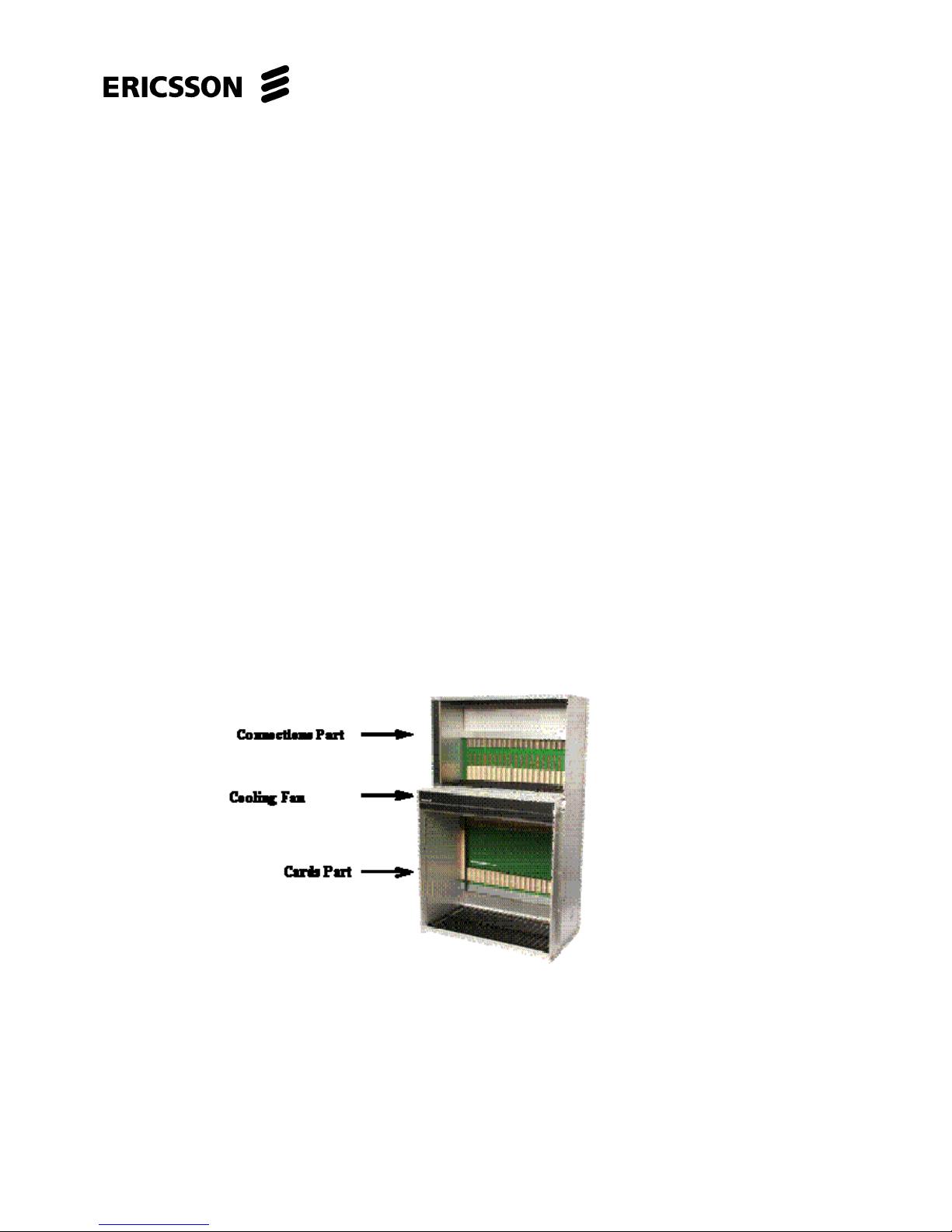
2.3.2 EDA 2530 Subrack
The EDA 2530 subrack comprises 22 slots for the service units and 22 slots for the
interface modules and is divided into three parts:
a. A bottom part (Electronic Part) composed of 22 slots housing the electronic
units – Network Interface Common Parts units and Subscriber Interface
channel units.
b. The top part (Connection Part) comprising the 22 slots for the interface
modules – Power and Alarm Interface (containing the two Power connectors,
the alarm connections and synchronisation connections), and the interface
modules corresponding to the Subscriber Interface units in the Electronic
Part.
c. Between the subrack top and bottom parts is the fan unit (FAN) (151-
2984/02) optimising the air forced circulation within the subrack.
Figure 2.3 – EDA 2530 Subrack
d. The type of subrack deployed for the EDA 2530 is the S20 Chassis, SE
code CA10EM, ME code 133-1555/03.
Page 15

EDA 2530 Commissioning Procedure for Cable and Wireless Access
1/153 22-FGC 101 0239/2 Uen Rev J 2010-04-01
© Ericsson AB 2010
Commercial in confidence
15 (200)
2.4 Subrack Composition
2.4.1 Composition Rules
2.4.1.1 Units Composition:-
• Common Part (CP) unit is fitted in position 1 only (slot 22 will not be used) in the
lower part of the subrack (the electronic part).
• 64xADSL2+ and 64xPOTS/VoIP electronic units can be fitted in positions 2 to 21
in the lower part of the subrack.
• 32 x SHDSL electronic units can be fitted in positions 20 and 21 and then 18 and
19 in the lower part of the subrack
• Generally when one electronic unit is inserted in the subrack, one “Connection”
Unit is required in the upper part of the subrack directly above it, with the
exception of the Common Part unit. The type of connection unit is identified in
Section 2.4.5 – Subrack Connection Units.
• Electronic units configured as a protection unit do not require a Connection Unit.
• The Power Supply Connection unit is located in the upper shelf in slot 22.
2.4.1.2 Units Composition with 1+1 Protection (Not used):-
Common Part units can be protected with 1+1 protection. This protection type
requires one worker unit and one protection unit.
This protection scheme is not revertive automatically. When 1+1 Protection is
utilised it is mandatory to insert the protected unit in position 1 and the protection
unit in position 22.
Page 16
EDA 2530 Commissioning Procedure for Cable and Wireless Access
1/153 22-FGC 101 0239/2 Uen Rev J 2010-04-01
© Ericsson AB 2010
Commercial in confidence
16 (200)
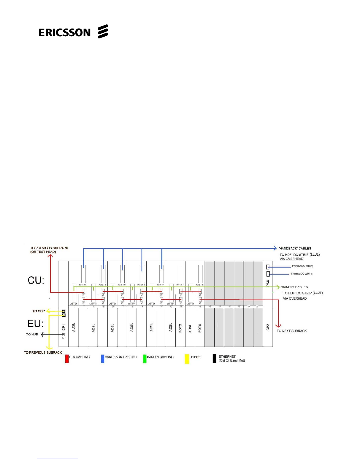
2.4.2 EDA2530E Standard Configuration for CWA Parent and Stand Alone
Shelf
This sub-section describes the standard configuration for CWA EDA2530 DLE
(EDAxx01) Parent and Stand Alone shelves only. The site engineer must refer to
the site specific configuration information for the site being commissioned.
This standard configuration allows for additional units to be provided at a later date
with minimal changes to the existing configuration.
The 64 x ADSL2+ units are inserted in even numbered slots from slot 2 up to slot 18
in increasing order towards the right.
The 64 x POTS/VoIP units are inserted in odd numbered slots from slot 3 up to slot
19 in increasing order towards the right.
Note that each 64 x ADSL and 64 x POTS unit has it’s relevant 64 x COMBI
Interface + I/O POTS + TAM Connection Unit (02HAT 00282 AAQ) fitted above the
pair of units. (A protection unit does not require an associated Connection Unit.)
Each 32 x SHDSL unit has one 32 x TAM Connection Unit (02HAT00136AAR) fitted
directly above the unit.
The 32 x SHDSL units are inserted in slots 20 and 21 and then in slots 18 and 19 if
more than two SHDSL units are required.
Figure 2.4 – EDA 2530 Example Configuration for CWA Shelf
Page 17

EDA 2530 Commissioning Procedure for Cable and Wireless Access
1/153 22-FGC 101 0239/2 Uen Rev J 2010-04-01
© Ericsson AB 2010
Commercial in confidence
17 (200)
At present, the standard configuration for 64 x ADSL and 64 x POTS units are not
provided with protection units. This is as specified by the Customer.
From the COMBI cards, 64-pair cables run via Overhead Runways to 100-pair IDC
strips located on the Handover Distribution Frame (HDF).
From the 32 x TAM Connection Unit, 32-pair cables run via Overhead Runways to
100-pair IDC strips located on the Handover Distribution Frame (HDF).
From the HDF blocks, 100-pr cable runs to the BT MDF. HDF blocks and HDF-to-
MDF cabling are provided by BT
HANDIN cabling (from HDF blocks designated LLUT or LLUX) allows connection to
C&W subscribers via the BT ‘last mile’ copper connection. Broadband traffic is
aggregated in the EDA 2530 & routed to the C&W Network via Backhaul fibre from
the Common Part board.
HANDBACK cabling (from HDF blocks designated LLUL) routes POTS telephony
traffic back to the BT Network.
For a pair with a POTS/VoIP card, telephony traffic is routed to the C&W
Network via Backhaul and thus HANDBACK cabling is NOT required.
Where a new EDA2530 Subrack is fitted on a site with an existing EDA2510
Subrack, the new Subrack will become the PARENT & the EDA2510 will become
the CHILD: the existing Backhaul fibre will be re-directed to the EDA2530 & a new
EDA-to-EDA fibre link provided. The EDA2510 will then sub-tend from the
EDA2530.
Page 18
EDA 2530 Commissioning Procedure for Cable and Wireless Access
1/153 22-FGC 101 0239/2 Uen Rev J 2010-04-01
© Ericsson AB 2010
Commercial in confidence
18 (200)
2.4.3 Network Interface Units
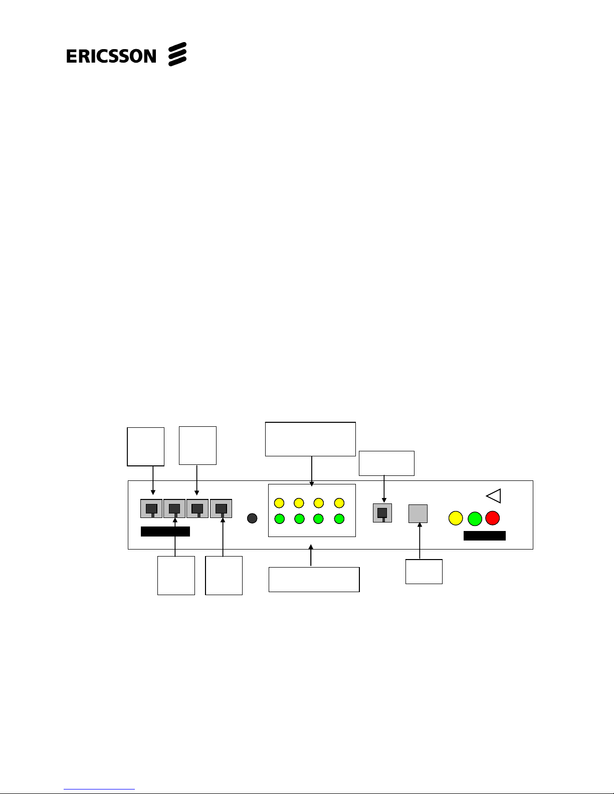
2.4.3.1 Common Part Unit (02HAT 00103 ACY)
IP 44G + Sync Common Part Unit for EDA 2530.
The Common Parts units contain both the electronics controlling the EDA 2530
(Controller, Matrix, Alarm Unit) and Network Interfaces. The Worker unit is located
in slot 1 and the Protection unit in slot 22 (not used).
The optic fibre cables (Tx and Rx) from the network are terminated on the
Worker network card SFP sockets. If MSP protection is configured optic
fibre/coaxial cables (Tx and Rx) from the network are also terminated on the
Protection network card.
If there is a failure on the Worker network interface then control is automatically
switched to the Protection network interface. If there is no MSP protection the optic
fibre cables (Tx and Rx) will need to be manually disconnected from the Worker unit
(slot 1) and re-connected to the Protection unit (slot 22). When replacing the optical
fibres to the network card, the service will be lost but the Protection card will
maintain the cross-connections and alarm functions.
For line protection, a pair of fibres can be terminated on the Worker card (slot 1) and
another pair on the Protection card (slot 22).
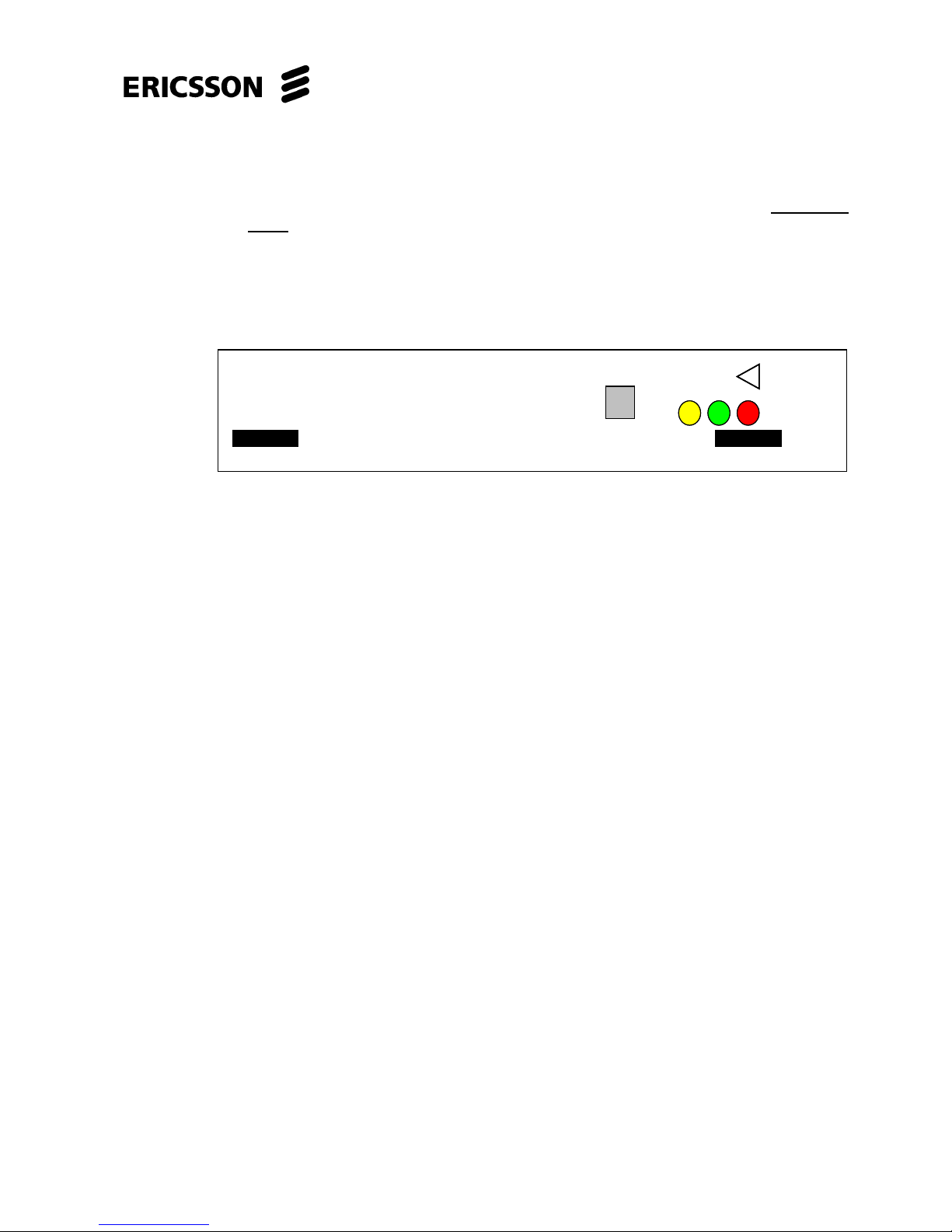
Figure 2.5 – IP 44G + Sync Common Part Unit 02HAT 00103 ACY
T
PWR
RS232
ETH
02HAT 00103 ACY
CP 2530
ETHERNET
RJ45
RS232
RJ12
RESET
PORT
1/1/2/3
Gig Eth
1
2
3
4
LIN
K
ACTIVIT
Y
YELLOW LEDS =
Activity Status of
Ethernet Links
GREEN LEDS =
Ethernet Link Status
PORT
1/1/2/1
Gig Eth
PORT
1/1/2/4
Gig Eth
PORT
1/1/2/2
Gig Eth
T
PWR
RS232
ETH
02HAT 00103 ACY
CP 2530
ETHERNET
RJ45
RS232
RJ12
RESET
PORT
1/1/2/3
Gig Eth
1
2
3
4
LIN
K
ACTIVIT
Y
1
2
3
4
LIN
K
ACTIVIT
Y
YELLOW LEDS =
Activity Status of
Ethernet Links
GREEN LEDS =
Ethernet Link Status
PORT
1/1/2/1
Gig Eth
PORT
1/1/2/4
Gig Eth
PORT
1/1/2/2
Gig Eth
Page 19

EDA 2530 Commissioning Procedure for Cable and Wireless Access
1/153 22-FGC 101 0239/2 Uen Rev J 2010-04-01
© Ericsson AB 2010
Commercial in confidence
19 (200)
The front of the card contains the following Interfaces:-
Network Ports - Gigabit Ethernet
There are four Network Gigabit Ethernet sockets, Port 1/1/2/1, Port 1/1/2/2, Port
1/1/2/3, and Port 1/1/2/4, using pluggable SFP modules.
The SFP module types are:-
• 1000Base-SX 850nm Interface (SU57AD), LC connector.
• 1000Base-LX 1310nm Interface (SU57AE), LC connector.
• 1000Base-EX 1310nm Interface (SU57AJ), LC connector.
• 1000Base-ZX 1550nm Interface (SU57AF), LC connector.
Ethernet Port 10Base-T
This RJ45 socket (5102209-0461) is used to connect to the LAN network, for OutBand Management (OBM) and for LCT use during commissioning.
Cabling Note: The Ethernet port can use standard Cat 5 screened cable (Common
Code = 1301042-0019) with standard RJ45 connector (5102169).
Serial Interface Port
This RS-232 RJ12 serial port is not normally used by the on-site engineer for
commissioning, but is utilised in Section 5.2 to download the equipment software to
the CP card’s Compact Flash.
LEDs
The card front is equipped with 3 LED’s whose functions are as follows.
T (yellow) On unit normal activity
Off unit has a protecting role
Blinking configuration is being changed
PWR (green) On unit is powered up
ALARM (red) Off normal activity
On internal alarm.
Blinking external alarm
DIP SWITCH SETTING:-
(Refer to the Section 10 Appendix)
On the Common Part Unit (02HAT00103ACY) check that DIP Switch SW600
(located bottom left near front panel) is set to the default settings, as shown below:-
Pin 1 = OFF
Pin 2 = OFF
Pin 3 = OFF
Pin 4 = OFF
Pin 5 = ON
Page 20
EDA 2530 Commissioning Procedure for Cable and Wireless Access
1/153 22-FGC 101 0239/2 Uen Rev J 2010-04-01
© Ericsson AB 2010
Commercial in confidence
20 (200)
2.4.4 Subscriber Interface Units
The EDA 2530 Subrack uses the following Subscriber interface units:-
a. The 64 x ADSL2+ cards can be configured in even slots from 2 to 20.
b. The 64 x POTS/VoIP cards can be configured in odd slots from 3 to 21.
c. The 32 x SHDSL cards can be configured in slots 18, 19, 20 and 21.
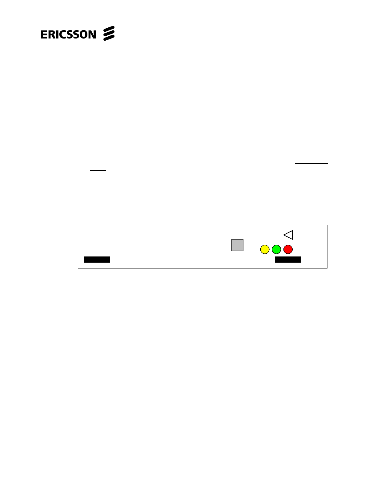
2.4.4.1 64 x ADSL2+ Unit (02HAT00162AAD)
EDA 2530 subrack:- The 64 x ADSL2+ card should be equipped in the Even Slots
Only, from slots 2 to slot 20 with up to a maximum of ten cards, providing a
maximum of 640 lines. Each 64 x ADSL2+ card requires its relevant Connection
Unit to be fitted above the 64 x ADSL2+ card. This unit can provide ADSL and
ADSL2+ services.
Note: When used as part of a 64 x ADSL2+ and POTS/VoIP Unit, the Connection
Unit required is the 64 x Combi I/F + In/Out POTS + TAM ETSI Connection Unit
(02HAT 00252 AAU).
Figure 2.6 – 64 x ADSL2+ Unit
The functions of the LEDs are as follows.
T (yellow) On unit normal activity
Off unit has a protecting role
Blinking configuration is being changed.
PWR (green) On unit is powered up
ALARM (red) Off normal activity
On internal alarm.
Blinking external alarm
T
PWR
RS232
02HAT 00162 AAD
ADSL2+ x 64
T
PWR
RS232
02HAT 00162 AAD
ADSL2+ x 64
T
PWR
RS232
02HAT 00162 AAD
ADSL2+ x 64
T
PWR
RS232
02HAT 00162 AAD
ADSL2+ x 64
Page 21
EDA 2530 Commissioning Procedure for Cable and Wireless Access
1/153 22-FGC 101 0239/2 Uen Rev J 2010-04-01
© Ericsson AB 2010
Commercial in confidence
21 (200)
2.4.4.2 64 x POTS/VoIP Unit (02HAT00198AAM)
EDA 2530 subrack:- The 64 x POTS/VoIP Unit should be fitted in the Odd Slots
Only, from slots 3 to slot 21 with up to a maximum of ten cards, providing a
maximum of 640 lines. Each 64 x POTS/VoIP card requires its relevant Connection
Unit to be fitted above the 64 x POTS/VoIP card.
Note: When the combination of 64 x ADSL2+ and 64 x POTS/VoIP Units are
used, the Connection Unit required is the 64 x COMBI I/F + IN/Out POTS + TAM
ETSI Connection Unit (02HAT00282AAQ).
Figure 2.7 – 64 x POTS/VoIP Unit
The card front is equipped with 3 LED’s whose functions are as follows.
T (yellow) On unit normal activity
Off unit has a protecting role
Blinking configuration is being changed.
PWR (green) On unit is powered up
ALARM (red) Off normal activity
On internal alarm.
Blinking external alarm
T
PWR
RS232
02HAT 00198 AAM
POTS/VoIPx 64
T
PWR
RS232
02HAT 00198 AAM
POTS/VoIPx 64
Page 22
EDA 2530 Commissioning Procedure for Cable and Wireless Access
1/153 22-FGC 101 0239/2 Uen Rev J 2010-04-01
© Ericsson AB 2010
Commercial in confidence
22 (200)
2.4.4.3 32 x SHDSL Unit (02HAT00274AAE)
The 32 x SHDSL card can be equipped in slots 20 and slot 21 with up to a maximum
of two cards per subrack, providing a maximum of 64 lines. Each 32 x SHDSL card
requires its relevant Connection Unit (02HAT00136AAR) to be fitted above the 32 x
SHDSL card.
Figure 2.8 - 32 x SHDSL Unit Front Panel
The functions of the LEDs are as follows.
T (yellow) On unit normal activity
Off unit has a protecting role
Blinking configuration is being changed.
PWR (green) On unit is powered up
ALARM (red) Off normal activity
On internal alarm.
Blinking external alarm
T
PWR
RS232
02HAT 00274 AAE
SHDSL x 32
T
PWR
RS232
02HAT 00274 AAE
SHDSL x 32
Page 23

EDA 2530 Commissioning Procedure for Cable and Wireless Access
1/153 22-FGC 101 0239/2 Uen Rev J 2010-04-01
© Ericsson AB 2010
Commercial in confidence
23 (200)
2.4.5 Subrack Connection Units
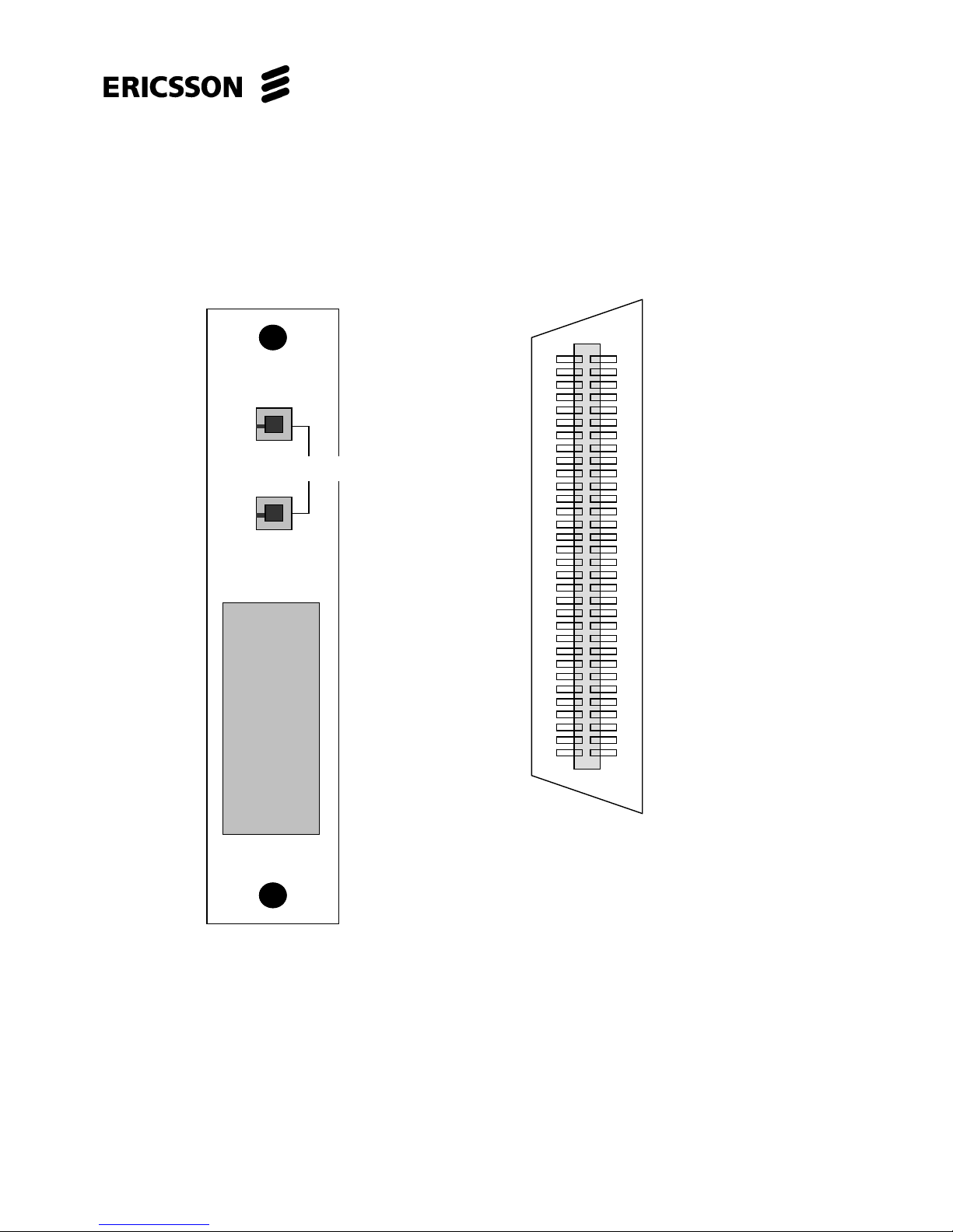
The EDA 2530 Subrack uses the following Connection Units:-
• Power Supply /Alarms / Sync Connection Unit - 151-2975/53
• 64 x COMBI Interface + I/O POTS + TAM ETSI Connection Unit -
02HAT00252AAU (Double unit width)
• 32 x TAM Connection Unit (02HAT 00136 AAR) - for SHDSL connections.
2.4.5.1 Power Supply Connection and Alarm Unit (151-2975/53)
Required for S20 Chassis 133-1555/03
This unit supplies power to all the devices in the subrack and is required for
Grounding Contacts and Synchronisation.
This unit is inserted in slot 22 in the upper shelf of the subrack.
Figure 2.9 - Power Supply Connection and Alarm Unit (151-2975/53)
Table 2.1 – Power Connector Pinout for Power Supply Connection & Alarm Unit (151-2975/53)
Slot 22 (151-2975/53) VB1 Slot 22 (151-2975/53) VB2
Pin Signal Function Pin Signal Function
1 - B1 Battery 1 negative voltage 1 - B2 Battery 2 negative voltage
2 +B1 Battery 1 positive voltage 2 +B2 Battery 2 positive voltage
3 Not used 3 Not used
4 +B1 Battery 1 positive voltage 4 +B2 Battery 2 positive voltage
5 - B1 Battery 1 negative voltage 5 - B2 Battery 2 negative voltage
5-Way D Type
Connector for
DC Power
Supply 1
25-Way D
Type Male
Connector for
ALARMS
5-Way D Type
Connector for
DC Power
Supply 2
1.0/2.3 Female
Coaxial
Connectors
S
y
nc 1 & 2 IN
ALARMS
151-2975/53
VB1
VB2
VB1
VB2
1
2
PWR
PWR
ALARMS
151-2975/53
VB1
VB2
VB1
VB2
1
2
PWR
PWR
Page 24

EDA 2530 Commissioning Procedure for Cable and Wireless Access
1/153 22-FGC 101 0239/2 Uen Rev J 2010-04-01
© Ericsson AB 2010
Commercial in confidence
24 (200)
Description Pin Signal
INT_AC 1 Summarized INTERNAL alarm
------- 2, 4 Not used
PIO1 5 Incoming ground contact nr. 1
PIO3 6 Incoming ground contact nr. 3
PIO5 7 Incoming ground contact nr. 5
PIO4 8 Incoming ground contact nr. 4
PIO8 9 Incoming ground contact nr. 8
PIO6 10 Incoming ground contact nr. 6
PIO7 11 Incoming ground contact nr. 7
PIO2 12 Incoming ground contact nr. 2
GND 13, 14 Ground
------ 15, 25 Not used
Table 2.2 – Alarm Connector Pinout for Power Supply Connection & Alarm Unit (151-2975/53)
Page 25

EDA 2530 Commissioning Procedure for Cable and Wireless Access
1/153 22-FGC 101 0239/2 Uen Rev J 2010-04-01
© Ericsson AB 2010
Commercial in confidence
25 (200)
2.4.5.2 64 x COMBI I/F + I/O POTS + TAM ETSI Connection Unit (02HAT00282AAQ)
Front Panel:
Figure 2.10 – 64 x COMBI Interface + I/O POTS + TAM ETSI Connection Unit
(02HAT00282AAQ)
128-Pin DIN Connector
From UNIT Front
02HAT00282AAQ
64 x COMBI I/F + I/O
POTS + TAM ETSI
LINE
1 - 64
POTS
1 - 64
LINE
TEST
ACCESS
32d
1d
1a
32a
TOP
If the POTS connectors are cabled to the existing POTS
exchange then the 60 x POTS VoIP unit MUST NOT
be
fitted.
128-Pin DIN Connector
From UNIT Front
02HAT00282AAQ
64 x COMBI I/F + I/O
POTS + TAM ETSI
LINE
1 - 64
POTS
1 - 64
LINE
TEST
ACCESS
32d
1d
1a
32a
TOP
1d
1a
32a
TOP
If the POTS connectors are cabled to the existing POTS
exchange then the 60 x POTS VoIP unit MUST NOT
be
fitted.
Page 26
EDA 2530 Commissioning Procedure for Cable and Wireless Access
1/153 22-FGC 101 0239/2 Uen Rev J 2010-04-01
© Ericsson AB 2010
Commercial in confidence
26 (200)
Note: This unit occupies two slots in the upper shelf and is fitted above the 64 x
ADSL2+ unit (In Even Slot 2) and the optional associated 64 x POTS/VoIP unit (In
Odd Slot 3). This unit will be fitted in slots 2 and 3, 4 and 5, 6 and 7, 8 and 9, 10
and 11, 12 and 13, 14 and 15, 16 and 17, 18 and 19 as required. IMPORTANT: If
the POTS/VoIP unit is fitted then the POTS connectors MUST NOT
be used
COMBO Card DIN Connector Pin Designations
SIGNAL PIN SIGNAL PIN
Line 1 a/b 1a 2a Line 33 a/b 1c 2c
Line 2 a/b 3a 4a Line 34 a/b 3c 4c
Line 3 a/b 5a 6a Line 35 a/b 5c 6c
Line 4 a/b 7a 8a Line 36 a/b 7c 8c
Line 5 a/b 9a 10a Line 37 a/b 9c 10c
Line 6 a/b 11a 12a Line 38 a/b 11c 12c
Line 7 a/b 13a 14a Line 39 a/b 13c 14c
Line 8 a/b 15a 16a Line 40 a/b 15c 16c
Line 9 a/b 17a 18a Line 41 a/b 17c 18c
Line 10 a/b 19a 20a Line 42 a/b 19c 20c
Line 11 a/b 21a 22a Line 43 a/b 21c 22c
Line 12 a/b 23a 24a Line 44 a/b 23c 24c
Line 13 a/b 25a 26a Line 45 a/b 25c 26c
Line 14 a/b 27a 28a Line 46 a/b 27c 28c
Line 15 a/b 29a 30a Line 47 a/b 29c 30c
Line 16 a/b 31a 32a Line 48 a/b 31c 32c
Line 17 a/b 1b 2b Line 49 a/b 1d 2d
Line 18 a/b 3b 4b Line 50 a/b 3d 4d
Line 19 a/b 5b 6b Line 51 a/b 5d 6d
Line 20 a/b 7b 8b Line 52 a/b 7d 8d
Line 21 a/b 9b 10b Line 53 a/b 9d 10d
Line 22 a/b 11b 12b Line 54 a/b 11d 12d
Line 23 a/b 13b 14b Line 55 a/b 13d 14d
Line 24 a/b 15b 16b Line 56 a/b 15d 16d
Line 25 a/b 17b 18b Line 57 a/b 17d 18d
Line 26 a/b 19b 20b Line 58 a/b 19d 20d
Line 27 a/b 21b 22b Line 59 a/b 21d 22d
Line 28 a/b 23b 24b Line 60 a/b 23d 24d
Line 29 a/b 25b 26b Line 61 a/b 25d 26d
Line 30 a/b 27b 28b Line 62 a/b 27d 28d
Line 31 a/b 29b 30b Line 63 a/b 29d 30d
Line 32 a/b 31b 32b Line 64 a/b 31d 32d
Table 2.3 – DIN Connector Pinout for 64 x COMBI Interface + I/O POTS + TAM
ETSI Connection Unit (02HAT00282AAQ)
Page 27

EDA 2530 Commissioning Procedure for Cable and Wireless Access
1/153 22-FGC 101 0239/2 Uen Rev J 2010-04-01
© Ericsson AB 2010
Commercial in confidence
27 (200)
Figure 2.11 - 64 Pair COMBO Card to HDF Cable Assembly (RPM251026/10m)
Page 28

EDA 2530 Commissioning Procedure for Cable and Wireless Access
1/153 22-FGC 101 0239/2 Uen Rev J 2010-04-01
© Ericsson AB 2010
Commercial in confidence
28 (200)
Figure 2.12 - 64 Pair COMBO to HDF Cable Wiring Diagram (RPM251026/10m)
Page 29
EDA 2530 Commissioning Procedure for Cable and Wireless Access
1/153 22-FGC 101 0239/2 Uen Rev J 2010-04-01
© Ericsson AB 2010
Commercial in confidence
29 (200)
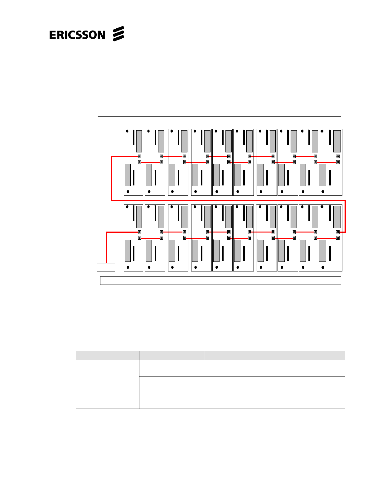
Interconnection Cables for ITAM Connection Unit (02HAT00282AAQ)
Connect the NX Test cable to upper Line Test Access socket on slot 2 and 3 unit.
Connect RJ45 to RJ45 cable from lower Line Test Access socket on slot 2 and 3
unit to lower Line Test Access socket on slot 4 and 5 unit. Connect upper LTA
socket on slot 4 and 5 unit to upper LTA socket on slot 6 and 7 unit and repeat to
daisy chain each unit into the Test Bus.
Figure 2.13 – ITAM Connection Unit (02HAT00282AAQ) Interconnection
On a two EDA shelf site, connect RJ45 to RJ45 cable from the upper LTA socket on slot 20
and 21 unit on the fully equipped Lower shelf, to the upper LTA socket on slot 2 and 3 unit
on the Upper shelf. On the Upper shelf, connect RJ45 to RJ45 cable between the Line Test
Access sockets to daisy chain each unit into the Test Bus.
DESCRIPTION CABLE CODES DESCRIPTION
1HAU62575AAV 50mm LT Bridging cable between adjacent
COMBO cards (terminated with RJ45 plugs)
06ZZ7050 10m STP CAT5E LT cable to connect to
previous subrack (requires terminating with
RJ45 plugs)
LT Cables (ITAM)
2 x 46CJ9002 RJ45 Plugs for LT cable
NxTest
Upper 2 3 4 5 6 7 8 9 10 11 12 13 14 15 16 17 18 19 20 21
Lower 2 3 4 5 6 7 8 9 10 11 12 13 14 15 16 17 18 19 20 21
NxTest
Upper 2 3 4 5 6 7 8 9 10 11 12 13 14 15 16 17 18 19 20 21
Lower 2 3 4 5 6 7 8 9 10 11 12 13 14 15 16 17 18 19 20 21
Page 30
EDA 2530 Commissioning Procedure for Cable and Wireless Access
1/153 22-FGC 101 0239/2 Uen Rev J 2010-04-01
© Ericsson AB 2010
Commercial in confidence
30 (200)
2.4.5.3 32 x TAM Connection Unit (02HAT 00136 AAR)
This unit is a Connection Unit for the 32 x SHDSL line units and is located in the
connection part slot above the 32 x SHDSL unit. It also provides Line Test Access
connections for connection to the TAM equipment.
Figure 2.14 – 32 x TAM Connection Unit
LINE
1 - 32
02HAT 00136 A A R
32 x TAM
LTA
LINE
1 - 32
02HAT 00136 A A R
32 x TAM
LTALTA
32
33 1
64
From UNIT Front
TOP
64-Pin Centronics Connector
Page 31

EDA 2530 Commissioning Procedure for Cable and Wireless Access
1/153 22-FGC 101 0239/2 Uen Rev J 2010-04-01
© Ericsson AB 2010
Commercial in confidence
31 (200)
32 x TAM Centronics Connector Pin Designations
SHDSL 2-Wire circuits SHDSL 4-Wire circuits
SIGNAL PIN SIGNAL PIN Interface
Line 1 a/b 1 33 Line 1 a/b 1 33 Interface
Line 2 a/b 2 34 Line 2 a/b 2 34 1
Line 3 a/b 3 35 Line 3 a/b 3 35 Interface
Line 4 a/b 4 36 Line 4 a/b 4 36 2
Line 5 a/b 5 37 Line 5 a/b 5 37 Interface
Line 6 a/b 6 38 Line 6 a/b 6 38 3
Line 7 a/b 7 39 Line 7 a/b 7 39 Interface
Line 8 a/b 8 40 Line 8 a/b 8 40 4
Line 9 a/b 9 41 Line 9 a/b 9 41 Interface
Line 10 a/b 10 42 Line 10 a/b 10 42 5
Line 11 a/b 11 43 Line 11 a/b 11 43 Interface
Line 12 a/b 12 44 Line 12 a/b 12 44 6
Line 13 a/b 13 45 Line 13 a/b 13 45 Interface
Line 14 a/b 14 46 Line 14 a/b 14 46 7
Line 15 a/b 15 47 Line 15 a/b 15 47 Interface
Line 16 a/b 16 48 Line 16 a/b 16 48 8
Line 17 a/b 17 49 Line 17 a/b 17 49 Interface
Line 18 a/b 18 50 Line 18 a/b 18 50 9
Line 19 a/b 19 51 Line 19 a/b 19 51 Interface
Line 20 a/b 20 52 Line 20 a/b 20 52 10
Line 21 a/b 21 53 Line 21 a/b 21 53 Interface
Line 22 a/b 22 54 Line 22 a/b 22 54 11
Line 23 a/b 23 55 Line 23 a/b 23 55 Interface
Line 24 a/b 24 56 Line 24 a/b 24 56 12
Line 25 a/b 25 57 Line 25 a/b 25 57 Interface
Line 26 a/b 26 58 Line 26 a/b 26 58 13
Line 27 a/b 27 59 Line 27 a/b 27 59 Interface
Line 28 a/b 28 60 Line 28 a/b 28 60 14
Line 29 a/b 29 61 Line 29 a/b 29 61 Interface
Line 30 a/b 30 62 Line 30 a/b 30 62 15
Line 31 a/b 31 63 Line 31 a/b 31 63 Interface
Line 32 a/b 32 64 Line 32 a/b 32 64 16
Table 2.4: Centronics Connector Pinout for 32 x TAM Connection Unit
(02HAT00136AAR)
Page 32

EDA 2530 Commissioning Procedure for Cable and Wireless Access
1/153 22-FGC 101 0239/2 Uen Rev J 2010-04-01
© Ericsson AB 2010
Commercial in confidence
32 (200)
2.4.6 Fan Tray (151-2984/02)
Figure 2.15 - Fan Unit
The Fan system ensures there is air circulation inside the subrack electronic part by
regulating fan speed as a function of temperature.
In the event of failure of one fan, the remaining ones increase their speed to the
maximum value to ensure proper equipment aeration. The system is located in the
central front part of the EDA 2530 subrack.
WARNING: In a fully equipped subrack, the equipment cannot work for more than
five minutes without the Fans.
End of section
Page 33

EDA 2530 Commissioning Procedure for Cable and Wireless Access
1/153 22-FGC 101 0239/2 Uen Rev J 2010-04-01
© Ericsson AB 2010
Commercial in confidence
33 (200)
3 Resources
The following equipment is required to carry out the tests described in this
document.
3.1 Documentation
The following documentation is required to commission the EDA 2530.
No. Description Code Qty
1 This document – EDA 2530 Commissioning
Procedure for Cable and Wireless Access.
2/153 22-FGC 101
0239 Uen
1
2 The EDA 2530 Software and Firmware Release
Note for the release of the EDA 2530 being
commissioned.
1
3 Customer specific Configuration information i.e.
Floor Plan, EDA 2530 Rack Layout, EDA 2530
Subrack equipment allocations, Cable Running Out
Lists.
1
3.2 Tools
No. Description Code Qty
1 Anti Static Wrist Strap and connection cable. 1
2 Anti Static bags for Slide in Units or Anti Static
containers.
As
required
3 Screwdrivers – Flat Blade and Crosshead. 2
4 Side Cutters 1
5 Krone IDC Connection tool see picture CWA013 2
6 Continuity Tester (Buzzer) for checking new cables. 1
7 T-Bar Unit Extraction Tool 151-2765/01 1
3.3 Test Equipment
Record details of the test equipment used on the Record of Test Equipment Form.
Approved equivalents may be used if the items specified are not available.
Page 34

EDA 2530 Commissioning Procedure for Cable and Wireless Access
1/153 22-FGC 101 0239/2 Uen Rev J 2010-04-01
© Ericsson AB 2010
Commercial in confidence
34 (200)
3.3.1 PC Connection Cables for Commissioning
Cable for connecting the Local Controller Ethernet Port to the EDA 2530 Common
Part Card. .
RJ45 Crossover Cable - Local Controller Ethernet Port to EDA 2530
Common Part Card
RJ45 Connector RJ45 Connector
Signal Pin Pin Signal
TD+ 1 3 RD+
TD- 2 6 RD-
RD+ 3 1 TD+
RD- 6 2 TD-
TD = Transmit Data RD = Receive Data
No. Description Code Qty
1 A PC to run EDA2530 LCT application (Min specifications
Pentium III 750MHz, 542Mb Ram, 200Mbyte free space,
CD-ROM, resolution 1024x768). Operating System XP or
Vista.
1
2 EDA 2530 Local Controller Software CD for the release of
the EDA 2530 being commissioned. (S38-xxxx/xx.xx.xx)
1
3 RJ45 Crossover cable for connecting the Local Controller
Ethernet Port to the EDA 2530. Refer to Section 3.3.1.
(Q4273) 1
4 RS232 Serial Cable Set, used to connect the Common
Part Unit (CP) RS232 interface to the PC serial COM
port. (Refer to Section 3.4.1 for details)
CWA0002
1
5 Digital Multimeter 1
6 “Golden Modem” multi-level xDSL service tester, with
ADSL /G.SHDSL module interfaces. Capable of ATU-R
and STU-R modem operation modes or an ADSL
modem, Eg. Linksys AM200 ADSL2+ modem.
1
7 SHDSL Modem Eg. Billion BiPAC 8520 up to 4.6Mbps
(4-wire SHDSL) Bridge/Router
1
8 Optical Power Meter with adapter lead for LC connection. 1
9 HDF block 2 pole to RJ11 test cord (Banana plugs) CWA006 1
10 HDF block 2 pole to RJ11 test cord CWA007 1
11 HDF Krone block 2 pole to RJ11 test cord CWA008 1
12 Butt Telephone Test Set with either internal or external
DSL/POTS filtering. Eg. Fluke TS-25D Telephone Test
kit. (Which includes DSL/POTS filtering)
1
13 RJ11 ADSL filter for Test Telephone 1
Page 35

EDA 2530 Commissioning Procedure for Cable and Wireless Access
1/153 22-FGC 101 0239/2 Uen Rev J 2010-04-01
© Ericsson AB 2010
Commercial in confidence
35 (200)
3.4 Test Cables
No. Description Code Qty
1 LC to LC single mode optical link. 2
2
Coaxial jumper cables 75Ω terminated with 2 x (1.0/2.3)
(BT Type 54) connectors
(Q4272) 2
3 DDF Loop Back Cables terminated with 2 x Type 43
connectors.
1HAM 10656 ABT
or (Q4232A)
32
4 xDSL line cable (Terminated with RJ12 connector at NT
modem end, with pins 3 and 4 wired to the a and b leg of
the line under test at the MDF).
Note: The “Golden Modem” test equipment includes the
line cable (RJ11), terminated with crocodile clips to
connect to the MDF Line termination (IDC connection).
1
Page 36

EDA 2530 Commissioning Procedure for Cable and Wireless Access
1/153 22-FGC 101 0239/2 Uen Rev J 2010-04-01
© Ericsson AB 2010
Commercial in confidence
36 (200)
3.4.1 RS232 Serial Cable Set (151-2502/01)
This cable is required for connection of the Common Part unit (CP) RS232 interface
to the PC serial COM port, for initial configuration.
IMPORTANT WARNING: Connect this cable to the PC before connecting the RJ12
connector to the Common Part. You must disconnect the RJ12 connector from the
Common Part before connecting or disconnecting any 9-Way connector to the PC.
The operator must NOT switch ON or switch OFF power to the PC while it is
connected to the Common Part card.
1
6
RJ12
Sub-D 9pin FEMALE
1
2
3
4
5
6
7
8
9
1
2
3
4
5
6
7
8
9
Sub-D 9pin FEMALE
SERIAL INTERFACE 1
SERIAL IN TER F ACE 2
Female
Connector
9-Pin Sub-D
Female
Connector
SERIAL INTERFACE 1
SERIAL INTERFACE 2
9-Pin Sub-D
Insertion Key
1
6
RJ12
5
1
9
6
rear view
Code: 151-2502/01
MONITOR
MAINTENANCE
Page 37

EDA 2530 Commissioning Procedure for Cable and Wireless Access
1/153 22-FGC 101 0239/2 Uen Rev J 2010-04-01
© Ericsson AB 2010
Commercial in confidence
37 (200)
3.5 Local Craft Terminal (LCT) Installation
With reference to the equipment handbook, install the software packages on the PC
relevant to the EDA Local Craft Terminal. If the correct release of LCT software is
already loaded on your PC ignore this section and go to Section 4.
3.5.1 Removal of Old Issue of EDA Hub Software
If the Access Hub LCT software has been installed previously, follow these steps to
remove it before installing the new version.
a. Close any EDA Local Terminal application, including the PortSrv
(PortServer) program.
b. To remove the EDA Local Craft Terminal software package installed by this
setup procedure, use the "Start -> Settings -> Control Panel ->
Add/Remove Program" utility in the Control Panel to remove the "AXH
Local Terminal xx.yy.zz" software.
c. To remove the EDA Local Craft Terminal Easy On software package
installed by this setup procedure, use the "Start -> Settings -> Control
Panel -> Add/Remove Program" utility in the Control Panel to remove the
"BMS xx.yy.zz" software. EasyOn software is named as “BMS”.
d. From the "Add/Remove Program" utility in the Control Panel, you can also
remove the Java, ITCL, and Acrobat Reader packages, if you need to
remove them.
3.5.2 Installation of Local Operator Software on P.C.
The Local Operator software is supplied on CD-ROM its identification code being
CXP_901_3007_1_R3B_06 [LCT rel. 07.02.06].
The CD ROM provides the following software packages:
• ITCL release 3.3.1
• Java version 5.0 update 15
• Acrobat Reader release 7.0.8
• EDA-AXH LCT release 07.02.06
• LCT EasyOn Addon release R3B06
• LCT 07.02.06 GA EC1 Patch
Page 38

EDA 2530 Commissioning Procedure for Cable and Wireless Access
1/153 22-FGC 101 0239/2 Uen Rev J 2010-04-01
© Ericsson AB 2010
Commercial in confidence
38 (200)
a. Insert the CD-ROM into the CD ROM drive of the PC.
b. If the PC is equipped with autorun the file readme.txt will be displayed
otherwise display it by double clicking the readme.txt file.
c. The document readme.txt contains the instructions to be carried out for the
installation of the software.
For further information, refer to the Operator’s Handbook.
3.5.3 Install Application Software From CD ROM
Note: If Windows NT is used, all the applications must be installed as
Administrator user.
a. Remove any previous version of EDA Local Craft Terminal. Refer to section
3.5.1 Removal of Old Issue of Access Hub Software.
b. Open up the Windows Explorer application in order to access the CD
inserted in the CD-ROM drive.
c. Install Java version 1.5.0 update 15, double-click on the "jre-1_5_0_15-
windows-i586-p.exe" file in the Java folder “CXC_172_4901_R2A_01” on
the CD-ROM drive to install it.
Follow the setup wizard to complete the installation, confirming the default
selections when in doubt.
d. If your Windows PC does not have ITCL 3.3.1 installed, double-click on the
"setup.exe" file in the ITCL folder “CXC_172_4904_R1B_01”on the CD-
ROM drive to install it.
Note: ITCL 3.3.1 is installed at the fixed location "C:\itcl3.3" .
e. If your Windows PC does not have Adobe Acrobat Reader release 7.0.8 or
higher installed, double-click on the "AdbeRdr708_en_US.exe" file in the
Acrobat folder “CXC_172_4902_R1A_01” on the CD-ROM drive to install it.
Follow the setup wizard to complete the installation, confirming the default
selections when in doubt.
f. Install the AXH LCT application, double-click on the "setup.exe" file in the
AXH LCT folder “CXC_172_4905_R3B_05”on the CD-ROM drive to install
it.
Follow the setup wizard to complete the installation, confirming the default
selections when in doubt.
g. Install the LCT-EASYON-ADDON application: double-click on the
"setup.exe " file in the LCT-EASYON folder “CXC_172_4906_R3B_06”on
the CD-ROM drive to install it.
Page 39

EDA 2530 Commissioning Procedure for Cable and Wireless Access
1/153 22-FGC 101 0239/2 Uen Rev J 2010-04-01
© Ericsson AB 2010
Commercial in confidence
39 (200)
Follow the setup wizard to complete the installation, confirming the default
selections when in doubt. This program will be named as “BMS” when
installed.
h. After completing the installation of LCT-EASYON-ADDON, restart the
computer in order to update the Windows O.S. registry.
i. After the computer has restarted, copy the patch file “p_XdslLineCF.tcl”
from the “LCT 07.02.06 GA EC1 Patch” folder on the CD. Then paste it into
the following folder c:\Mv36bLT\lib\gui, to replace the existing
“p_XdslLineCF.tcl” file.
j. Copy and replace the existing file “setenv80_13.bat” with the latest one
provided, in folder C:\Mv36bLT\Lib\env (you may wish to backup the
existing file before doing so).
Note: If this file is not replaced then when loading the National Mapping file,
Columbia will be selected instead of the United Kingdom.
k. The LCT installation is now complete.
3.5.4 LCT 07.02.05 – Known Issue with Java Version 1.6
LCT 07.02.05 has a known issue with the National Mapping Tool and setting up the
repository location when Java version 1.6 has been installed.
To correct this issue the commissioning engineer must remove Java 1.6, the LCT, &
all of the LCT packages, then re-install them again but with Java version 1.5 before
attempting to configure any POTS card(s).
Perform the following steps:-
a. Uninstall Java 1.6 and all of it’s updates from the Windows Control Panel.
b. Uninstall the LCT then it’s suite of packages including “itcl”, Java 1.5
update 15, & the Easy on Addon known as “BMS”, from the Windows
Control Panel.
c. Delete all of the Java directory(s) in C:\Program Files (ensure you have
removed the Java programs from Windows Control Panel first before you
do this).
d. Reboot the PC.
e. Re-install “itcl”, then “Java 1.5 update 15”, then “LCT 07.02.05”, then Easy
on Addon known as “BMS”.
f. Reboot the PC after Easy on Addon known as “BMS” has been installed.
Page 40

EDA 2530 Commissioning Procedure for Cable and Wireless Access
1/153 22-FGC 101 0239/2 Uen Rev J 2010-04-01
© Ericsson AB 2010
Commercial in confidence
40 (200)
g. After the computer has restarted, install the LCT 07.02.05 EC1 correction
patch. Copy the patch file “p_XdslLineCF.tcl” from the “LCT 07.02.06 GA
EC1 Patch” folder on the LCT CD. Then paste it into the following folder
c:\Mv36bLT\lib\gui, to replace the existing “p_XdslLineCF.tcl” file.
End of section
Page 41

EDA 2530 Commissioning Procedure for Cable and Wireless Access
1/153 22-FGC 101 0239/2 Uen Rev J 2010-04-01
© Ericsson AB 2010
Commercial in confidence
41 (200)
4 Commissioning Requirements
4.1 Description Of Testing Activities
The testing described in this document is the functional testing on lines chosen by
sampling those present in the system.
During Section 5.2, only the Common Part unit in slot 1 is inserted in the EDA 2530
subrack.
Note: The other units are inserted for configuration from Section 5.3.
4.2 Test Records
The commissioning test records at the end of this document must be completed as
the testing progresses. A complete set of Test Records must be completed for each
EDA 2530 (EDAxx01) Parent and Stand Alone shelf being commissioned.
When all testing has been completed successfully, both the Ericsson representative
and Customer’s representatives must complete the Certification of Tests Form at the
end of this document. If the Customer’s representative is not present on site enter
N/A (Not Available) for the Customer representative.
4.3 Preliminary Checks
4.3.1 Equipment Positioning
Check the equipment positioning corresponds to the implementation plan.
4.3.2 Card Equipping
Check that the correct quantity and type of equipment cards have been supplied to
the contract requirements. The electrical cards should be partially inserted into their
allocated slot positions, ensuring that the unit edge connectors do NOT make
accidental contact with the shelf connectors. Carefully insert the Connection Units
into the start of the shelf runner. Ensure that the unit is exactly level and then gently
slide the unit forward until a resistance is felt. A further gentle push on the unit front
panel will ensure that the unit connector engages with the shelf pin connections. Do
NOT force the unit into the shelf, as this will damage the shelf edge connectors.
Check that the positions not occupied by cards have the appropriate covers fitted.
Refer to Section 2.4.2 for Unit Equipping Rules and Standard Configuration for
Cable and Wireless Parent and Stand Alone shelf.
Page 42

EDA 2530 Commissioning Procedure for Cable and Wireless Access
1/153 22-FGC 101 0239/2 Uen Rev J 2010-04-01
© Ericsson AB 2010
Commercial in confidence
42 (200)
4.3.3 Cabling
Check that the positions of service or signal cable terminations on electrical and
optical distribution frames, or on other equipment, comply with the Site
Implementation Plan.
Check that the 64 pair cables (Lines and POTS) are tied on the provided cable
supports. Check that Line cables are linked to the Connection Unit through the
supports supplied with the equipment.
Page 43

EDA 2530 Commissioning Procedure for Cable and Wireless Access
1/153 22-FGC 101 0239/2 Uen Rev J 2010-04-01
© Ericsson AB 2010
Commercial in confidence
43 (200)
4.3.4 Power Supply and Grounding Connections
VB1 VB2
Pin Signal Function Pin Signal Function
1
- B1 Negative Voltage of Battery 1
1
- B2 Negative Voltage of Battery2
2 +B1 Positive Voltage of Battery 1 2 +B2 Positive Voltage of Battery 2
3 Not used 3 Not used
4 +B1 Positive Voltage of Battery 1 4 +B2 Positive Voltage of Battery 2
5 - B1
Negative Voltage of Battery 1
5 - B2
Negative Voltage of Battery 2
Note: The 5 Pin D-Type Connector on the Power Cable is Female.
Figure 4.1 - Power Supply Connection Unit (151-2975/53) Pin Allocations
Figure 4.2 Power Supply/Earth Arrangement to Power Supply Connection Unit
Pin 1 2 3 4 5
M
C
B
1
M
C
B
2
-50 V Supply 1
(
Battery 1)
Pin 1 2 3 4 5
M
C
B
3
M
C
B
4
-50 V Supply 2
(
Battery 2
)
Rack Earth Bar
0 V
Power Supply Connection Unit
(151-2975/53) Slot 22 - Socket Vb1
Power Supply Connection Unit
(151-2975/53) Slot 22 - Socket Vb2
Main Earth Bar
0 V
5 Pin D-Type Connector (Male)
on Power Supply Connection
Unit (151-2975/53)
Pin 1 2 3 4 5
Grey Grey Grey Grey
Grey Grey
Blue
Blue Blue
Page 44

EDA 2530 Commissioning Procedure for Cable and Wireless Access
1/153 22-FGC 101 0239/2 Uen Rev J 2010-04-01
© Ericsson AB 2010
Commercial in confidence
44 (200)
4.4 Earthing And D.C. Supply Checks
These tests are classified as SAFETY TESTS.
There are different variants of Power Supply Connection Unit available, depending
on the type of subrack and the customer requirements.
SUBRACK
DESCRIPTION
SUBRACK CODE Power Supply - Right
S20 Flexible Connections 133-1555/03 151-2975/53 (Slot 22)
The EDA 2530 Power Supply Connection Unit (151-2975/53 incorporates two 5 pin
D-Type connectors. Each connector allows for connecting two –50 volt and two
earth cables to provide the duplicated power supply to each 5 pin D-Type connector.
The EDA 2530 cabinet will be supplied by two –50 volt power feeds, each protected
by an external circuit breaker rating or fuse of 32 Amps. The two Earth cables will
be connected to the EDA 2530 Earth bar.
Record the external circuit breaker or fuse rating on the Equipment Checks Test
Record.
In the United Kingdom (UK) the main –50v supply (Supply 1) is connected to two
Single-Pole 16 Amp Miniature Circuit Breakers (MCB 1 and MCB 2) fitted on the
circuit breaker panel at the top of the EDA 2530 cabinet. These two 16 Amp MCB’s
are connected to Socket Vb1 on the Power Supply Connection Unit (151-2975/53) in
slot 22. The main –50v supply (Supply 2) is connected to two Single-Pole 16 Amp
Miniature Circuit Breakers (MCB 3 and MCB 4). These two 16 Amp MCB’s are
connected to Socket Vb2 on the Power Supply Connection Unit (151-2975/53) in
slot 22. Other countries may have different types of Isolators or Circuit Breakers
depending on local requirements and regulations.
Check the circuit breakers or fuses in the customer's distribution equipment are
switched OFF or open. Check the EDA 2530 cabinet circuit breakers are switched
OFF. Disconnect the 5 pin D-Type connectors from Socket Vb1 and Socket Vb2 on
the Power Supply Connection Unit in slot 22.
Measurement: Check there is a connection between the EDA 2530 cabinet and
the earth bar. Check the resistance is less than 1 ohm, measured between
cabinet metalwork and an adjacent point on the earth bar. Record the
measured value in the Test Record.
At the customer's DC distribution equipment switch ON the isolators or circuit
breakers, or insert the fuses, for the feeds to the EDA 2530 Cabinet. If the DC
distribution is from an EF80 or similar distribution, insert the two 32 Amp fuses.
Check the supplies at the cabinets are of the correct polarity and lie in the range -
48 V ±20% (-38.4v to -57.6v). Record the measured value on the Main Power
Supply Voltage Check Test Record.
Page 45

EDA 2530 Commissioning Procedure for Cable and Wireless Access
1/153 22-FGC 101 0239/2 Uen Rev J 2010-04-01
© Ericsson AB 2010
Commercial in confidence
45 (200)
4.5 Power Supply Connection Unit Check
Switch ON Circuit Breaker MCB 1 at the top of the EDA 2530 cabinet. Check for –
50 volts on Pin 1 of the D-Type connector for Socket Vb1 on Power Supply
Connection Unit in slot 22. Switch OFF MCB 1 and check the –50 volts is removed.
Switch ON Circuit Breaker MCB 2 at the top of the EDA 2530 cabinet. Check for –
50 volts on Pin 5 of the D-Type connector for Socket Vb1. Switch OFF MCB 2 and
check the –50 volts is removed. Check for Earth (0 volts) on Pin 2 and Pin 4.
(Refer to Figure 4.1 for the layout of the 5 pin D-Type connector).
Reconnect the 5 pin D-Type connector to Socket Vb1 on the Power Supply
Connection Unit in slot 22. Secure the connector by tightening the two fixing
screws. Switch ON MCB 1 and MCB 2 and check the Green “VB1” power LED is lit
on the Power Supply Connection Unit in slot 22.
Switch ON Circuit Breaker MCB 3 at the top of the EDA 2530 cabinet. Check for –
50 volts on Pin 1 of the D-Type connector for Socket Vb2 on Power Supply
Connection Unit in slot 22. Switch OFF MCB 3 and check the –50 volts is removed.
Switch ON Circuit Breaker MCB 4 at the top of the EDA 2530 cabinet. Check for –
50 volts on Pin 5 of the D-Type connector for Socket Vb2. Switch OFF MCB 4 and
check the –50 volt is removed. Check for Earth (0 volts) on Pin 2 and Pin 4. (Refer
to Figure 4.1 for the layout of the 5 pin D-Type connector).
Reconnect the 5 pin D-Type connector to Socket Vb2 on the Power Supply
Connection Unit in slot 22. Secure the connector by tightening the two fixing
screws. Switch ON MCB 3 and MCB 4 and check the Green “VB2” power LED is lit
on the Power Supply Connection Unit in slot 22.
4.5.1 Labelling
Check that the Circuit Breakers MCB 1, MCB2, MCB 3 and MCB 4 or alternative
power supply Circuit Breakers are labelled according to the provisions of the
‘Installation Standard for EDA 2530 Equipment’.
Check that the optical links or cable, Customer side and Network side, are labelled
according to the provisions of the ‘Installation Standard for EDA 2530 Equipment’ or
that their terminations can be identified.
Check that the strips of the distribution frames, onto which the equipment is
terminated, are labelled according to the provisions of the ‘Installation Standard for
EDA 2530 Equipment’.
Check that the equipment racks and subracks are labelled according to the
provisions of the ‘Installation Standard for EDA 2530 Equipment’.
End of section
Page 46

EDA 2530 Commissioning Procedure for Cable and Wireless Access
1/153 22-FGC 101 0239/2 Uen Rev J 2010-04-01
© Ericsson AB 2010
Commercial in confidence
46 (200)
This page is left intentionally blank to facilitate double sided printing.
Page 47

EDA 2530 Commissioning Procedure for Cable and Wireless Access
1/153 22-FGC 101 0239/2 Uen Rev J 2010-04-01
© Ericsson AB 2010
Commercial in confidence
47 (200)
5 Initial Configuration
Prior to testing, the Common Part IP unit requires configuring in accordance with the
parameters assigned to the system.
This section details the process to configure IP addresses/parameters needed for
management of the equipment from LCT and from the appropriate workstation for
network management.
For identification of the IP addresses/parameters assigned to the system, refer to
the Network planning guide.
5.1 IP Address Configuration Of PC Used As LCT
Before connecting the laptop to the Common Part IP unit, the laptop must be
configured to be in the same IP Network Address range as the Out of Band
Management IP Address of the EDA 2530.
Note: For Windows 2000 OS use step a, for Windows XP use step b, and for
Vista OS use step c, all other steps are common to Windows 2000/XP/Vista OS.
a. For Windows 2000
, left click on the Start button, then select Settings >
Control Panel.
Double left click on the Network and Dial-up Connections icon.
b. For Windows XP
, left click on the Start button, then select Control Panel.
Double left click on the Network Connections icon.
c. For Windows Vista
, left click on the Start button, then select Network >
Network and Sharing Center > Manage network connections.
d. Right click on Local Area Connection icon and then click Properties.
e. In the ‘LAN Properties’ window, use the scrollbar to move down the list.
f. For Windows 2000/XP select the ‘Internet Protocol (TCP/IP) entry, but for
Windows Vista select the ‘Internet Protocol Version 4 (TCP/IPv4) option,
then left click on the ‘Properties’ button.
Page 48

EDA 2530 Commissioning Procedure for Cable and Wireless Access
1/153 22-FGC 101 0239/2 Uen Rev J 2010-04-01
© Ericsson AB 2010
Commercial in confidence
48 (200)
g. In the ‘Internet Protocol (TCP/IP) Properties’ window, left click in the
~ Use the following IP Address’ radio button.
h. In the ‘IP Address’ field, enter an IP Address for the laptop compatible with
the Out of Band IP Address of all the EDA 2530 shelves. For this project a
suitable laptop IP Address is 150.150.150.16.
Set the Laptop IP Address to 150.150.150.16
Note: The EDA 2530 IP Address is 150.150.150.4
i. In the ‘Subnet Mask’ field, enter the subnet mask for the EDA 2530 node.
This will always be the same for all EDA 2530 shelves.
Enter 255.255.255.0
j. Leave the ‘Default Gateway’ field blank.
k. Left click the OK button to save and close the ‘Internet Protocol (TCP/IP)
Properties’ window.
l. Left click the OK button to save and close the ‘LAN Properties’ window.
Click on Yes to reboot the laptop if prompted.
m. This step only applies to Ericsson personnel running Symantec antivirus
and anti spyware applications on Windows VISTA OS.
Page 49

EDA 2530 Commissioning Procedure for Cable and Wireless Access
1/153 22-FGC 101 0239/2 Uen Rev J 2010-04-01
© Ericsson AB 2010
Commercial in confidence
49 (200)
Disable the antivirus and anti spyware protection by “Stop”ing the
Symantec Endpoint Client and Symantec Management Client, as described
in the follow steps:-
Select Start then right click on Computer, select the path: Manage >
Continue > Services and applications > Services
Right click on Symantec Management Client, and select Stop.
Right click on Symantec Endpoint Protection, and select Stop.
Now close all open windows.
n. Start the Command prompt click on Start > Programs > Accessories >
Command Prompt.
o. At a command prompt (MS-DOS prompt) type ipconfig then press Return.
The following will be displayed:-
IP Address 150.150.150.16
Subnet Mask 255.255.255.0
Default Gateway
Check the displayed values are correct. If correct proceed to the next
section. If incorrect repeat section 5.1.
p. Type exit then press RETURN to quit the Command Prompt menu.
Page 50

EDA 2530 Commissioning Procedure for Cable and Wireless Access
1/153 22-FGC 101 0239/2 Uen Rev J 2010-04-01
© Ericsson AB 2010
Commercial in confidence
50 (200)
5.2 Common Part Card CF Download
Follow this section to update the Common Part card with the appropriate software
build for CWA. The following functions are performed on the CP card:-
• Reformat the Compact Flash device.
• Download CP software R4.21 to the CF card.
Download requirements:-
• PC to be installed with a terminal emulation application, examples are
Hyperterminal and Teraterm, with the following settings:-
Port: COM 1
Data speed: 38400 bits/s
Data Bits: 8
Stop Bit: 1
Parity: None
Flow control: XON/XOFF
• PC to be installed with EDA2530 LCT application version 07-02-04.
• RS232 serial lead type 151-2502/01, to connect between the PC serial port (or
USB) and the CP card’s serial port.
• CAT5 cross-over Ethernet cable, to connect between the PC LAN port and the
CP card’s ETH port.
Take antistatic precautions when handling the units, fit an ESP wristband.
a. Remove the CP card from slot 1.
b. Remove the Compact Fash card.
c. Reinsert the CP card into slot 1, without the CF card fitted.
d. Connect the Ethernet cable & serial cable to the CP card.
e. For Ericsson staff only, on the PC turn off “Symantec Endpoint Client” and
“Symantec Management Client”.
f. Copy the “LoadCF 4.21GA” files onto the LCT PC hard drive, at location
C:\Mv36bLT\tftp. These are:-
“Delivery” folder
“CPIP-LLB.bin”
“uImage”
“uRDimage”
Page 51

EDA 2530 Commissioning Procedure for Cable and Wireless Access
1/153 22-FGC 101 0239/2 Uen Rev J 2010-04-01
© Ericsson AB 2010
Commercial in confidence
51 (200)
g. From the Windows Start menu run the “TFTP Server” application, select
path StartÆAll ProgramsÆLocal Terminal 0x.0y.0zÆTFTP Server.
h. Start the terminal session on the serial port, press <return> to display the
command prompt. Then type the following:-
printenv<return> (This displays the Common Part IP Address)
setenv<space>serverip<space>150.150.150.16<return> (PC’s ip address)
setenv<space>bootdelay<space>5<return> (set a 5 sec boot delay)
saveenv<return>
printenv<return> (to print display settings)
i. Remove the CP card from slot 1.
j. Replace the Compact Flash card.
k. Reinsert the CP card into slot 1, with the CF card fitted.
l. At the second countdown press <return> key within 5 seconds.
m. At the command prompt type the following:-
ver<return>
Check that IPCP HLB (High Level Boot) is displayed.
printenv<return>
Check IP addresses etc are displayed
loadcf<return>……(now loads the CF)
n. Wait for “Loadcf completed” to be displayed. On the tftp server look for the
transfer of “up.tar.bz2” file. This will take around 3 minutes.
o. Wait for the command prompt “bash-2.05a#”, then type the following:-
reboot<return>
p. Wait around 3 min for the following to be displayed:-
Bank 1: Not valid
Active
Bank 2: Not valid
Not active
Fatal: No valid bank found!
Page 52

EDA 2530 Commissioning Procedure for Cable and Wireless Access
1/153 22-FGC 101 0239/2 Uen Rev J 2010-04-01
© Ericsson AB 2010
Commercial in confidence
52 (200)
Do not be alarmed, this message is to be expected.
q. At the command prompt type the following:-
cd<space>/home/Bank1<return>
ls<space>-l
r. Check that “_UP.ID” file is present.
s. At the command prompt type the following:-
mv<space>_UP.ID<space>UP.ID<return>
ls<space>-l
t. Check that “UP.ID” file is present (must be upper case).
u. At the command prompt type the following:-
reboot<return>
v. Wait for the following to be displayed:-
Bank 1: Valid
Active
Bank 2: Not valid
Not active
Running manager
w. Wait for the last message to be displayed, this will be “update Trap
logs……….Trap di CP……..“, at this point press <return> to display
Login:”.
x. The CF download is now complete.
Page 53

EDA 2530 Commissioning Procedure for Cable and Wireless Access
1/153 22-FGC 101 0239/2 Uen Rev J 2010-04-01
© Ericsson AB 2010
Commercial in confidence
53 (200)
5.3 Subrack Equipping
With the power now applied to the subrack, equip the subrack with the slide in units
in the following order:-
a. Insert the 64x COMBI Interface + I/O POTS + TAM ETSI Connection
Unit(s) 02HAT00282AAQ first into the upper half of the subrack, into their
designated slot position(s). Refer to the Site Installation Documentation
pack. This unit occupies two slots in the upper shelf, it is fitted to slots 2
and 3, 4 and 5, 6 and 7, 8 and 9, 10 and 11, 12 and 13, 14 and 15, 16 and
17, 18 and 19, as appropriate.
Each of these Connection units is associated to a dedicated pair of 64 x
ADSL2+ and 64 x POTS/VoIP unit(s).
b. Insert the 64 x ADSL2+ unit(s) 02HAT00162AAD next into the lower half of
the subrack, into their designated slot position(s). Refer to the Site
Documentation pack. These units are inserted in even numbered slots
starting from slot 2 up to slot 18 in increasing order towards the RHS.
c. Insert the 64 x POTS/VoIP unit(s) 02HAT00198AAM into the lower half of
the subrack, into their designated slot position(s). Refer to the Site
Installation Documentation pack. These units are inserted in odd numbered
slots starting from slot 3 up to slot 19 in increasing order towards the RHS.
Note: If a 64x POTS/VoIP unit is fitted then the “POTS” connectors on the
relevant Connection unit MUST NOT
be used
d. Insert the 32 x TAM Connection Unit(s) 02HAT00136AAR first into the
upper half of the subrack, into their designated slot position(s). This unit
occupies one slot in the upper shelf, it is fitted to slots 18, 19, 20 and 21, as
appropriate, above where SHDSL units are required.
e. Insert the 32 x SHDSL unit(s) 02HAT00274AAE into the lower half of the
subrack, into their designated slot position(s). Refer to the Site Installation
Documentation pack. These units are inserted in slots 20 then 21. If more
than two SHDSL units are required these will be inserted in slots 18 and 19.
When powered up, the 64 x ADSL2+ card or 32 x SHDSL card will then
send a reset signal to the Connection Unit as part of its start-up
sequence. So it is important that the connection unit is inserted first
and the ADSL card or SHDSL card is inserted second.
Note: Refer to Sections 2.4.2/2.4.3 for Unit Equipping Rules and Standard
Configuration for the CWA EDA2530 Parent and Stand Alone shelf.
f. The units will now be automatically created, if created correctly the alarm
status for each equipped unit will become green.
Page 54

EDA 2530 Commissioning Procedure for Cable and Wireless Access
1/153 22-FGC 101 0239/2 Uen Rev J 2010-04-01
© Ericsson AB 2010
Commercial in confidence
54 (200)
5.4 Logon to The EDA 2530 Via LCT
a. Connect the PC to the Common Part card using the Ethernet cable (Ref:
3.3).
b. Select Start > All Programs > AXH-EDA Local Terminal xx.yy.zz >
PortSrv
c. Select Start > All Programs > AXH-EDA Local Terminal xx.yy.zz > AXH-
EDA Local Terminal
Or select the “AXH-EDA Local Terminal” shortcut from the desktop.
A window with ‘Starting Local Terminal. Please wait…’ will be displayed.
d. After around 15 seconds the ‘Equipment Logon’ window will be displayed.
e. Enter in the Equipment Address field, the IP Ethernet Address for the CP
unit, ie 150.150.150.4.
Then click on Logon.
f. If everything has been carried out correctly, then after around 2.5 minutes
the equipment view window will be displayed, showing the created unit(s).
Page 55

EDA 2530 Commissioning Procedure for Cable and Wireless Access
1/153 22-FGC 101 0239/2 Uen Rev J 2010-04-01
© Ericsson AB 2010
Commercial in confidence
55 (200)
5.5 Reset The Backplane EPROM
Before performing any configuration on a new EDA2530 it is important to clear the
backplane EPROM. This ensures the shelf and the CP card have the same
backplane parameters.
a. On the laptop start the Internet Browser.
b. Ensure the proxy server settings are disabled, as follows:-
From the browser top line menu select Tools > Connections tab > LAN
settings, from the LAN settings window ensure that all options are not
selected.
c. Select “OK” to save the settings, then “OK” in the Connections window to
return to the browser.
d. In the browser address field enter the default EDA 2530 IP address,
150.150.150.4 <RETURN>.
e. The “EDA-2500 Element Manager” screen will be displayed. Enter the
following login details:-
Username: “commissioning”
Password: “commissioning”
f. Select “Login”, then the HTTP shelf view will be displayed.
Page 56

EDA 2530 Commissioning Procedure for Cable and Wireless Access
1/153 22-FGC 101 0239/2 Uen Rev J 2010-04-01
© Ericsson AB 2010
Commercial in confidence
56 (200)
g. From the left-hand side options select “Commissioning” >
“IBMoE_Reset”. A warning message will be displayed, select “Continue”.
The backplane EPROM parameters will be aligned with the CP card.
h. In order to allow remote out of band management of the EDA 2530, the Out
of Band Management OBM Ethernet IP Address needs to be altered from
the default of 150.150.150.4 to allow for multiple EDA’s on each site. The
address must be modified in line with the following table.
DLE ID IP Address DLE ID IP Address DLE ID IP Address
0101 150.150.150.4 0201 150.150.150.8 0301 150.150.150.12
0102 150.150.150.5 0202 150.150.150.9 0302 150.150.150.13
0103 150.150.150.6 0203 150.150.150.10 0303 150.150.150.14
0104 150.150.150.7 0204 150.150.150.11 0304 150.150.150.15
0105 150.150.150.16 0205 150.150.150.17 0305 150.150.150.18
i. If the EDA 2530 default Out Band Management OBM IP address has to be
changed in line with the Network Plan, then from the left-hand side options
select “Commissioning” > “extEthIP”.
Page 57

EDA 2530 Commissioning Procedure for Cable and Wireless Access
1/153 22-FGC 101 0239/2 Uen Rev J 2010-04-01
© Ericsson AB 2010
Commercial in confidence
57 (200)
j. From the resulting window change the IP Address to a value in line with the
above table, also refer to the Network Planner’s guide for the site. Leave
the IP Network Mask address at 255.255.255.0, and select “Apply
Changes” to update the OBM IP address.
k. From the left-hand side options select “LOG OUT” to log out of the EDA
2500 Element Manager and return to the internet browser.
l. Close down the Internet Browser.
m. From the main LCT screen select Maintenance > Equipment reboot.
From the following window click on the “Warm reboot” button, select the
“Reboot” option and “Yes” to continue.
n. The equipment will log out of the LCT and the CP card will reboot.
o. Wait around 5 min before attempting to login again, this time using the new
OBM IP address.
5.6 Software Inventory Check
Check the Software Inventory on each 64 x ADSL2+ card, 64 x POTS/VoIP card
and 32 x SHDSL card. The software in the Common Part card identifies the
software release for the shelf. There is one acceptable release.
This table shows the Software R4.21 GA EC2 for the EDA 2530 cards.
EDA 2530 Software R4.21 GA EC2
Card Type Unit Code Software Code Release Date
CP 2530-IP 02HAT00103ACY CXC 172 4796 R3D R3D02 090529
64 x ADSL2+ 02HAT00162AAD CXC 172 3777 R2B R2B27 090129
64 x POTS/VoIP 02HAT00198AAM CXC 172 4797 R2B R2B30 090129
32 x SHDSL 02HAT00274AAE CXC 172 5103 R1B R1B18 090131
a. Logon to the EDA 2530 again.
b. Right click on the Common Part card in slot 1, select HW/SW Inventory
from the option menu.
c. In the window displayed, check that the Running Bank (Yes) contains the
correct software code and release. This is an example screen.
Page 58

EDA 2530 Commissioning Procedure for Cable and Wireless Access
1/153 22-FGC 101 0239/2 Uen Rev J 2010-04-01
© Ericsson AB 2010
Commercial in confidence
58 (200)
d. Click on Close to close the Inventory window.
e. Right click and hold over the 64x ADSL2+ card to be checked. Select
HW/SW Inventory from the menu.
f. In the window displayed, check that the Running Bank (Yes) contains the
correct software release. This is just an example screen.
g. Click on Close to close the Inventory window.
h. Check the “H/W and S/W Inventory” for all other new 64x ADSL2+ cards
and confirm that they have the correct H/W and S/W release.
Page 59

EDA 2530 Commissioning Procedure for Cable and Wireless Access
1/153 22-FGC 101 0239/2 Uen Rev J 2010-04-01
© Ericsson AB 2010
Commercial in confidence
59 (200)
i. Right click and hold over the 64x POTS/VoIP card to be checked. Select
HW/SW Inventory from the menu.
j. In the window displayed, check that the Running Bank (Yes) contains the
correct software release. This is just an example screen.
k. Click on Close to close the Inventory window.
l. Check the “H/W and S/W Inventory” for all new 64x POTS/VoIP cards and
confirm that they have the correct H/W and S/W release.
m. Right click and hold over the new 32 x SHDSL cards to be checked. Select
HW/SW Inventory from the menu.
n. In the window displayed, check that the Running Bank (Yes) contains the
correct software release. This is just an example screen.
o. Click on Close to close the Inventory window.
Page 60

EDA 2530 Commissioning Procedure for Cable and Wireless Access
1/153 22-FGC 101 0239/2 Uen Rev J 2010-04-01
© Ericsson AB 2010
Commercial in confidence
60 (200)
p. Check the “H/W and S/W Inventory” for all other new 32 x SHDSL cards
and confirm that they have the correct H/W and S/W release.
q. If the unit’s Software releases do not correspond with the releases listed in
the R4.21 Software table at the beginning of this sub-section, then upgrade
the unit’s software now by following Section 6.
Note: All of the units MUST
be at the correct release before the Common
Part card can be configured in Section 7.
End of Section
Page 61

EDA 2530 Commissioning Procedure for Cable and Wireless Access
1/153 22-FGC 101 0239/2 Uen Rev J 2010-04-01
© Ericsson AB 2010
Commercial in confidence
61 (200)
6 Software Download/Upgrade
The EDA Equipment can be upgraded by downloading an updated version of
software into all cards as required by downloading from the LCT PC, using TFTP
application (Trivial File Transfer Protocol).
a. Load all of the EDA2530 R4.21 GA EC2 software files onto the LCT PC
hard drive, at location C:\Mv36bLT\tftp\R4.21_GA_EC2
b. From the Windows Start menu run the “TFTP Server” application, select
path StartÆAll ProgramsÆAXH-EDA Local Terminal 0x.0y.0zÆTFTP
Server.
c. From the TFTP Server window, select “Browse” and navigate to the
software location specified in step a.
d. From the LCT select the path: Maintenance → Software Download, the
“System Software Download” screen will be displayed:-
e. The “TFTP IP address” field will be filled in with the IP address of the LCT
PC. Do not modify the “Server Path” address field, leave it set to default
path “./”.
Page 62

EDA 2530 Commissioning Procedure for Cable and Wireless Access
1/153 22-FGC 101 0239/2 Uen Rev J 2010-04-01
© Ericsson AB 2010
Commercial in confidence
62 (200)
f. Load a new configuration by clicking on the “New Conf” button. A new
window will be displayed:-
g. Double click on the “tftp” directory, then on the “R4.21_GA_EC2” directory,
to list the configuration files which have been stored at this location.
h. The “SwDownload.sdc” configuration file will be displayed.
i. The “SwDownload.sdc” file includes a line for each unit type linking to the
appropriate downloadable software files, as illustrated in the example
below:-
vdslx32-NP:CXC 172 4029 R2B:R2B27:CXC_172_4029_R2B27.tftp.s38
Page 63

EDA 2530 Commissioning Procedure for Cable and Wireless Access
1/153 22-FGC 101 0239/2 Uen Rev J 2010-04-01
© Ericsson AB 2010
Commercial in confidence
63 (200)
shdslx32-MultiServices:CXC 172 5103 R1B:R1B18:CXC_172_5103_R1B18.tftp.s38
potsx64-NP:CXC 172 4797 R2B:R2B30:64potsMngr0202.dz
potsx60-NP:CXC 172 6483 R1B:R1B36:60potsMngr0102.dz
isdnx32-SIP-4B3T-NP:CXC 172 4798 R2B:R2B27:32isdnMngr0202_R2B27.dz
isdnx32-SIP-2B1Q-NP:CXC 172 4798 R2B:R2B27:32isdnMngr0202_R2B27.dz
cp-2530-4xGbEth:CXC 172 4796 R3D:R3D02 :UP.tar.bz2
cp-2530-4xGbEth-NTP:CXC 172 4796 R3D:R3D02 :UP.tar.bz2
adslx64-NP:CXC 172 3777 R2B:R2B27:CXC_172_3777_R2B27.tftp.s38
adsl-isdnx64-NP:CXC 172 3777 R2B:R2B27:CXC_172_3777_R2B27.tftp.s38
1
st
field is the unit type.
2
nd
field is the software serial code and the software version.
3
rd
field is the file name.
j. Select the “SwDownload.sdc” configuration file, then “OK”, now start the
download process with a click on the “Download” button.
A warning window will ask for confirmation.
k. Click on the YES button to proceed with the software download.
l. The “System Software Download in progress” window will pop up.
During the connection to the TFTP server the Idle label will be displayed
and during the download process the Downloading… label will be visible.
Note the ‘Yellow’ LED flashes on card/s being downloaded.
m. If the download process has been successfully completed, the label
displayed inside the “System Software Download in progress” window
changes to “Download successful” and two new buttons will be visible:
the “Switch Software Bank” and the “Close” button.
Page 64

EDA 2530 Commissioning Procedure for Cable and Wireless Access
1/153 22-FGC 101 0239/2 Uen Rev J 2010-04-01
© Ericsson AB 2010
Commercial in confidence
64 (200)
Note the ‘Yellow’ LED is extinguished on the card/s when downloaded
successfully.
n. Click on the Close button if you do not want to switch the software bank.
o. If the download is successful, follow step (o) to perform the Bank Switch.
Otherwise go to step (q) or (r) as appropriate for the download result.
p. “Download successful”
After a successful software download, press the “Switch Software Bank”
button to start the software bank switch, then “Yes” to confirm.
A message will offer the last possibility to abort the operation.
At the end of the switch process, the Switching label changes to Sw itch
successful.
Then click on the Close button.
Note the ‘Yellow’ LED is lit on the card/s when switched successfully.
Page 65

EDA 2530 Commissioning Procedure for Cable and Wireless Access
1/153 22-FGC 101 0239/2 Uen Rev J 2010-04-01
© Ericsson AB 2010
Commercial in confidence
65 (200)
q. Check the correct software is running on the card downloaded. Position the
cursor on the Card. Right click with the mouse and select HW/SW
Inventory from the menu. The newly downloaded software will be shown
with the status of “Yes” in the “Running” column.
Once the software download has been successful, the process may need to
be repeated again when any other cards are added to the equipment at a
later date.
r. Result = “Download Failed”
If the download was unsuccessful, the “Download Failed” label will be
visible. The “System Software Download Status” window will display the
problems encountered during the software download. Close the windows
and go back to (i) and repeat the System Software Download process
again.
s. Result = “Download successful but incompatible databases”
After the download, an automatic check of the new software is performed,
to verify the compatibility between the database used for the new software
version and the one used for the previous software version. If they are
incompatible, the label “Download successful but incompatible
databases” will warn the operator.
IMPORTANT:
Press the Close button, the window will go back to the “System Software
Download” screen. DO NOT press the “Switch Forced Software Bank”
button.
Select the “Close” button again.
Page 66

EDA 2530 Commissioning Procedure for Cable and Wireless Access
1/153 22-FGC 101 0239/2 Uen Rev J 2010-04-01
© Ericsson AB 2010
Commercial in confidence
66 (200)
Note: If the new software downloaded in the equipment uses a
different type of database version than the existing one, a forced
switch MUST NOT
be performed from the LCT. If it is selected, the
configuration database will be corrupted and the CP card won’t
reboot.
If the result following download to the CP card is “Incompatible database”
then do not proceed any further commissioning the element, return the CP
card to the Product Support Centre and get a replacement CP unit loaded
with the correct software release.
t. Close all windows to return to the main LCT screen.
End of section
Page 67

EDA 2530 Commissioning Procedure for Cable and Wireless Access
1/153 22-FGC 101 0239/2 Uen Rev J 2010-04-01
© Ericsson AB 2010
Commercial in confidence
67 (200)
7 Configure IP and Ethernet Management
The following table gives a list of the site specific information required to commission
the EDA 2530, without this information the commissioning of the node cannot
commence. Most of this information is provided in the CWA “DLE planning”
spreadsheet, produced by CWA DLE Management.
CWA “DLE planning”
Ref.
Comissioning
Procedure/LCT
Ref.
Example / Comments
DSLAMID Node DLE ID
eg EANCN0102 (Norwich North), this is
site specific.
Specified in site SID document.
OOB IP Address
(Out Of Band)
150.150.150.x
Where x=4 (default) to 15
Out Of Band IP Address is determined
by the DLE ID, refer to Section 5.5.
S-VLAN SVID
21 or 22
To be specified by CWA.
If parenting EDA2530 to an existing
EDA2510, will use the same value as
used by the EDA2510.
Parent EDA2530 3200 + y
Child#1 EDA2530 200 + y
Child#2 EDA2530 1200 + y
Child#3 EDA2530 2200 + y
C-VLAN CVID
Where y = 1 to 64 for xDSL ports 1 - 64
Where y = 1 to 32 for SHDSL ports 1 32
Mask Mask Length
E.g. 30 or 31
Number of bits of subnet mask.
To be specified by CWA.
AHX IP Addr IBM IP Address
In Band Management IP Address.
To be specified by CWA.
BRAS IP Addr Route Gateway
IP Address
To be specified by CWA.
Page 68

EDA 2530 Commissioning Procedure for Cable and Wireless Access
1/153 22-FGC 101 0239/2 Uen Rev J 2010-04-01
© Ericsson AB 2010
Commercial in confidence
68 (200)
The following table gives a list of the additional site specific information required to
configure the POTS cards, without this information commissioning cannot
commence. This information is provided in the CWA “DLE planning” spreadsheet,
produced by CWA DLE Management.
CWA “DLE planning”
Ref.
Comissioning
Procedure/LCT
Ref.
Example / Comments
H248 Virtual Gateway
4 digit domain name.
H248 Virtual
Gateway 4 digit
Domain Name.
eg 0016-CLNEW (New Cross). This is
site specific and will be supplied by
C&W. Usually the same value as used
by the EDA2510
Primary Media
Gateway Controller
Domain name
Primary Media
Gateway
Controller
Domain name
eg iMSS-BULLDOG-01 This may be
regional and must be supplied by C&W.
Primary Media
Gateway Controller
IP Address
Primary Media
Gateway
Controller IP
Address
eg 83.146.63.27 (The MGWC IP
Address). This is Media Gateway
specific and must be supplied by C&W.
H.248 S-VLANS (/23
subnets
RTP Local IP
Address
Each POTS card has a unique site
specific IP Address.
POTS Card S-VLAN
ID
POTS Card SVLAN ID
Slot 3 = 151, Slot 5 = 152, Slot 7 = 153,
Slot 9 = 154, Slot 11 = 155, Slot 13 =
156, Slot 15 = 157, Slot 17 = 158, Slot
19 = 159, Slot 21 = 160
Perform all of this section to configure the EDA 2530 Common Part IP card from the
LCT.
Page 69

EDA 2530 Commissioning Procedure for Cable and Wireless Access
1/153 22-FGC 101 0239/2 Uen Rev J 2010-04-01
© Ericsson AB 2010
Commercial in confidence
69 (200)
7.1 Configure The Optical SFP Modules Gigabit Ethernet
Note1: If the EDA 2530 is to be the “Parent” node & subtend an existing
EDA 2510 node, then the backhaul SFP required for Port 1 (SU57AE
1310nm) will be recovered from the EDA 2510 SFP Port 3 when the two
nodes are migrated during a PEW, at a later date.
Note2: CP Port SFP1 will be utilised as the Network interface to backhaul to
the IP Network.
Note3: CP Port SFP2 (when fitted) will be used by the “Parent” to subtend
the “Child#1”, an EDA 2510 node.
Note4: CP Port SFP3 (when fitted) will be used by the “Parent” to subtend
the “Child#2”, an EDA 2530 node.
Note5: CP Port SFP4 (when fitted) will be used by the “Parent” to subtend
the “Child#3”, an EDA 2530 node.
Note6: SFP Modules approved by Marconi are ‘Moni Tagged’ and will be
configured automatically when inserted.
a. On the Common Part card:- (Check details with the site’s SID document)
Insert SFP1 module (if available) into Port 1 (SU57AE - 1310nm).
Insert SFP2 module (if supplied) into Port 2 (SU57AD - 850nm).
Insert SFP3 module (if supplied) into Port 3 (SU57AD - 850nm).
Insert SFP4 module (if supplied) into Port 4 (SU57AD - 850nm).
b. Right click on the CP Card and select SFP Provisioning from the sub
menu. The “CP-IP SFP/Port Provisioning” screen will appear.
Page 70

EDA 2530 Commissioning Procedure for Cable and Wireless Access
1/153 22-FGC 101 0239/2 Uen Rev J 2010-04-01
© Ericsson AB 2010
Commercial in confidence
70 (200)
Check from the table that the SFP parameters are correct with the type of
module(s) installed, check that each SFP is alarm free, ie the Alarm Status
is ‘not alarmed’.
If the EDA 2530 “Parent” is to subtend an existing EDA 2510, then the
backhaul SFP1 module won’t be available at this Commissioning
stage (will be available when the two node types are migrated). Even
though SFP1 is not physically present continue to provision the CP
Port 1 interface as detailed in the following steps:-
c. From the “CP-IP SFP/Port Provisioning” window select the row for CP Port
“1/1/2/1”.
d. Click on the “View Details/Modify selected SFP configuration” button.
The following window will be displayed:-
e. Leave “SFP MONI-tagged required” set to true (default).
Change “SFP Frame Type” to Eth1000.
Page 71

EDA 2530 Commissioning Procedure for Cable and Wireless Access
1/153 22-FGC 101 0239/2 Uen Rev J 2010-04-01
© Ericsson AB 2010
Commercial in confidence
71 (200)
Change the “SFP Medium Type” to Dual Fibre.
Set the “SFP Laser Wave Length (nm)” to 1310 for example. (Verify the
setting against the SID document for CP Port 1 SFP1 module.)
Leave “SFP connected to Y-Coupler” set to false (default).
f. Select the “Apply” button in the top right-hand corner to modify the
configuration.
g. Select “Refresh”, then “Close” to return to the “CP-IP SFP/Port Provisioning”
screen.
h. If the SFP2, SFP3, SFP4 module(s) have not configured correctly then repeat
the above steps c. to g. for CP Ports “1/1/2/2”, “1/1/2/3”, & “1/1/2/4” (as
appropriate). The settings are to be the same as Port “1/1/2/1” except for
setting the wave length to 850nm.
i. Select “Refresh” on the “CP-IP SFP/Port Provisioning” screen.
j. Check on the table that the parameters are correct with the type of SFP
installed, check that the SFP(s) are alarm free, ie the Alarm Status is ‘not
alarmed’.
k. Select “Close” to return to the main LCT window.
Page 72

EDA 2530 Commissioning Procedure for Cable and Wireless Access
1/153 22-FGC 101 0239/2 Uen Rev J 2010-04-01
© Ericsson AB 2010
Commercial in confidence
72 (200)
7.2 Configure CP Ethernet Interfaces
7.2.1 Configure CP Port 1
Configure CP Port 1 GigE interface to be the In Band Management interface.
a. Right click on the CP Card and select Ethernet Lines from the sub menu.
b. Select the “Port 1” button, then click on “Configure”, the following window
will be displayed:-
c. From the “Configuration” folder tick the Local In-Band Mng tick box. Then
click on the “Apply” button that is immediately to the left of the tick box.
d. Select the “MAU” folder, the following window will be displayed:-
Page 73

EDA 2530 Commissioning Procedure for Cable and Wireless Access
1/153 22-FGC 101 0239/2 Uen Rev J 2010-04-01
© Ericsson AB 2010
Commercial in confidence
73 (200)
e. In the “MAU AUTO NEGOTIATION” area of the window change the “Admin
Status” field from enabled to disabled. Now select the “Apply” button then
select “Refresh”.
f. Select another folder, & check that Port 1 interface changes colour from
Yellow to Green.
Note: The port status will only turn to Green if there is a signal on the fibre
and it is connected to the port.
7.2.2 Configure CP Port 2
Note: CP SFP Port 2 interface is used to subtend Child#1 (EDA 2510)
a. Select Port 2 and follow steps d. to f. of Section 7.2.1 above to configure CP
Port 2. Do NOT select the “Local In-Band Mng” option, this is required for CP
Port 1 only.
b. Select “Close” to return to the main LCT screen.
7.2.3 Configure CP Port 3 (If required)
Note: CP SFP Port 3 interface is used to subtend Child#2 (EDA 2530)
a. Select Port 3 and follow steps d. to f. of Section 7.2.1 above to configure CP
Port 3. Do NOT select the “Local In-Band Mng” option, this is required for CP
Port 1 only.
b. Select “Close” to return to the main LCT screen.
7.2.4 Configure CP Port 4 (If required)
Note: CP SFP Port 4 interface is used to subtend Child#3 (EDA 2530)
a. Select Port 4 and follow steps d. to f. of Section 7.2.1 above to configure CP
Port 4. Do NOT select the “Local In-Band Mng” option, this is required for CP
Port 1 only.
b. Select “Close” to return to the main LCT screen.
Page 74

EDA 2530 Commissioning Procedure for Cable and Wireless Access
1/153 22-FGC 101 0239/2 Uen Rev J 2010-04-01
© Ericsson AB 2010
Commercial in confidence
74 (200)
7.3 Configure EDA 2530 Tag Protocol ID/Bridging Parameters
Prior to configuring any services the EDA 2530 TPID should be configured, as
follows:-
a. From the top line menu select the path Configuration > IP/Ethernet
Management > Bridging Parameters.
b. From the” Equipment Level Bridging Parameters Configuration” window,
change the “Bridge Ethertype S (hex-str)” field from 88A8 to 8100.
c. Select the “Apply” button then the “Refresh” option.
Note: When TPID=8100 all VLAN tags (S+C) contained within received
traffic are ‘read’ and used to switch traffic. When TPID=88A8 only the outer
VLAN (S) tag is ‘read’ and used to switch traffic.
d. Select “Cancel” to return back to the main LCT screen.
Page 75

EDA 2530 Commissioning Procedure for Cable and Wireless Access
1/153 22-FGC 101 0239/2 Uen Rev J 2010-04-01
© Ericsson AB 2010
Commercial in confidence
75 (200)
7.4 ADSL Card Configuration Files
In order to commission the ADSL cards a set of generic ADSL configuration files will
be required for each site. These will be prepared in advance of the site
commissioning and will be supplied to the site commissioning engineer. The site
commissioning engineer will load these files and then modify the data to the site
configuration requirements. i.e. IP Addresses, and quantity of ADSL cards installed.
Create a folder “EDA2530 Generic ADSL Configuration Files” on your PC. Store the
Generic ADSL configuration folders and files in this folder.
Folder Name File Type/s File Quantity
ADSL Profiles .ap 1 for all sites. (Standard)
Static VLAN & VLAN Port Config .nsvm & .vlm 2 for all sites. (Standard)
Downstream Flows .dfc 10 files – 1 per even slot for all sites
PVC Config Parent - adsl .e42 10 files – 1 per even slot for all sites
PVC Config Child#1 - adsl .e42 10 files – 1 per even slot for all sites
PVC Config Child#2 - adsl .e42 10 files – 1 per even slot for all sites
PVC Config Child#3 - adsl .e42 10 files – 1 per even slot for all sites
File Name File Type File Quantity
xDSL profile Management – XDSL Line Profile .ap 1 for all sites. (Standard)
Static VLAN Management – Ports fixed .nsvm 1 for all sites. (Standard)
Static VLAN Management – Static VLANS fixed .vlm 1 for all sites. (Standard)
xDSL Bridge Management – Downstream Flows –
Slot x
.dfc 10 files – 1 per even slot for all
sites
xDSL Bridge Management – PVC Management –
Slot x
.e42 10 files – 1 per even slot for all
sites
7.5 SHDSL Card Configuration Files
In order to commission the SHDSL cards a set of generic SHDSL configuration files
will be required for each site. These will be prepared in advance of the site
commissioning and will be supplied to the site commissioning engineer. The site
commissioning engineer will load these files and then modify the data to the site
configuration requirements. i.e. IP Addresses, and quantity of SHDSL cards
installed.
Create a folder “EDA2530 Generic SHDSL Configuration Files” on your PC. Store
the Generic SHDSL configuration folders and files in this folder.
Page 76

EDA 2530 Commissioning Procedure for Cable and Wireless Access
1/153 22-FGC 101 0239/2 Uen Rev J 2010-04-01
© Ericsson AB 2010
Commercial in confidence
76 (200)
Folder Name File Type/s File Quantity
SHDSL Profiles .lcp & .psp 2 for all sites. (Standard)
Static VLAN & VLAN Port Config .nsvm & .vlm 2 for all sites. (Standard)
Downstream Flows .dfc 4 files – 1 for slots 18, 19, 20, 21 for all sites
PVC Config Parent - shdsl .e42 4 files – 1 for slots 18, 19, 20, 21 for all sites
PVC Config Child#1 - shdsl .e42 4 files – 1 for slots 18, 19, 20, 21 for all sites
PVC Config Child#2 - shdsl .e42 4 files – 1 for slots 18, 19, 20, 21 for all sites
PVC Config Child#3 - shdsl .e42 4 files – 1 for slots 18, 19, 20, 21 for all sites
File Name File Type File Quantity
SHDSL Line Profiles .lcp 1 for all sites. (Standard)
SHDSL Stack Profiles .psp 1 for all sites. (Standard)
Static VLAN Management – Ports fixed .nsvm 1 for all sites. (Standard)
Static VLAN Management – Static VLANS fixed .vlm 1 for all sites. (Standard)
xDSL Bridge Management – Downstream Flows –
Slot x
.dfc 4 files – 1 for slots 18, 19, 20,
21 for all sites
xDSL Bridge Management – PVC Management –
Slot x
.e42 4 files – 1 for slots 18, 19, 20,
21 for all sites
7.6 Configure Static VLANs
a. From the LCT main screen select the path Configuration > IP/Ethernet
Management > IP-CP Static VLAN. The following screen will be
displayed:-
b. Select the “Static VLANs” button, at the top left corner.
c. Select “File” then “Open”, then navigate to the relevant folder and select
the template file “Static VLAN Management – Static VLANS fixed.vlm”.
Select “Open” then the Bridge VLANs table will be filled in.
Page 77

EDA 2530 Commissioning Procedure for Cable and Wireless Access
1/153 22-FGC 101 0239/2 Uen Rev J 2010-04-01
© Ericsson AB 2010
Commercial in confidence
77 (200)
d. In the “Ne Name” column the template will load the default OOB IP
address of 150.150.150.4, the Node being commissioned is likely to have a
different one allocated to it. The Out Of Band IP Address is determined by
the DLE ID, refer to Section 5.5. Change the address (if necessary) in this
column for all entries, as follows:-
Change the 1
st
entry in this column to the correct IP address, select the 1st
entry, then left-click the 1
st
entry & drag down to the bottom of the column
to highlight all entries. Right click & select “Replicate cell”, all entries in the
“Ne Name” column will now be set to the required OOB IP Address.
e. In the “S-VLAN ID” column the template will load the default value of 22,
check with the CWA “DLE planning” document what the S-VLAN ID value
should be set to for the node being commissioned. This value will be either
21 or 22.
In the “S-VLAN ID” column change if necessary the value of the 1st entry,
to be 21 or 22 as appropriate.
f. In the “Command” column, in the 1
st
entry double click the empty field and
select the “create” option from the drop-down list. Select the 1
st
entry, then
click & drag down to the bottom of the column to highlight all entries. Right
click & select “Replicate cell”, all entries in the “Command” column will
now be set to “create”.
g. Select “Apply All” from the bottom LHS of the screen. The rows will turn
Green and under the “Result” column the field should display “OK”.
Page 78

EDA 2530 Commissioning Procedure for Cable and Wireless Access
1/153 22-FGC 101 0239/2 Uen Rev J 2010-04-01
© Ericsson AB 2010
Commercial in confidence
78 (200)
h. Select “Read Network” near the top of the screen, this will confirm the
configuration, if there are any incorrect entries they will be highlighted at
this point.
Page 79

EDA 2530 Commissioning Procedure for Cable and Wireless Access
1/153 22-FGC 101 0239/2 Uen Rev J 2010-04-01
© Ericsson AB 2010
Commercial in confidence
79 (200)
7.7 Adding Interfaces to the Static VLANs
a. Whilst still in the “Static VLANs Management” window, select the “Ports”
button at the top left corner. The “Define VLAN user port membership”
screen will be displayed.
b. Select “File” then “Open”, then navigate to the relevant folder and select
the template file “Static VLAN Management – Ports fixed.nsvm”. Select
“Open”, then the “Static VLAN Members” table will be filled in.
The following screen shows that this template file creates a “Parent” EDA
2530 with a single ADSL card configured in slot 2. It also creates the
necessary S-VLAN entries for Child#1 (EDA 2510 or EDA2530) which is
subtended from GigE Port 2.
Page 80

EDA 2530 Commissioning Procedure for Cable and Wireless Access
1/153 22-FGC 101 0239/2 Uen Rev J 2010-04-01
© Ericsson AB 2010
Commercial in confidence
80 (200)
Store the S-VLAN Table as follows:
a. In the “Ne Name” column the template will load the default OOB IP
address of 150.150.150.4, the Node being commissioned is likely to have a
different one allocated to it. The Out Of Band IP Address is determined by
the DLE ID, refer to Section 5.5. Change the address (if necessary) in this
column for all entries, as follows:-
Change the 1
st
entry in this column to the correct IP address, select the 1st
entry, then left-click the 1
st
entry & drag down to the bottom of the column
to highlight all entries. Right click & select “Replicate cell”, all entries in the
“Ne Name” column will now be set to the required OOB IP Address.
b. In the “S-VLAN ID” column, the three “Data-Inband” entries will be loaded
with the default value of 22, check with the CWA “DLE planning” document
what the S-VLAN ID value should be set to for the node being
commissioned. This value will be either 21 or 22.
In the “S-VLAN ID” column change if necessary the value of these three
entries, to 21 or 22 as appropriate.
c. In the “Command” column, in the 1
st
entry double click the empty field and
select the “addPort” option from the drop-down list. Select the 1
st
entry, left
click & drag down to the bottom of the column to highlight all entries. Right
click & select “Replicate cell”, all entries in the “Command” column will
now be set to “addPort”.
d. Select “Apply All” from the bottom LHS of the screen. The rows will turn
Green and under the “Result” column the field should display “OK”.
e. Select “Read Network” near the top of the screen, this will confirm the
configuration, if there are any incorrect entries they will be highlighted at
this point. Refer to the following screen.
Page 81

EDA 2530 Commissioning Procedure for Cable and Wireless Access
1/153 22-FGC 101 0239/2 Uen Rev J 2010-04-01
© Ericsson AB 2010
Commercial in confidence
81 (200)
7.7.1 Create S-VLANs for Additional ADSL Cards (If required)
The template file creates the VLAN data for the ADSL slot 2 card only, additional SVLANs must be created for other ADSL cards in the “DATA_INBAND” name,
perform the following:-
a. Double left-click on the “intLag//1/2” entry in “User Port Interface Name”
column.
b. In the “VLAN Egress Ports – entry 2” window select “Read NE”.
Page 82

EDA 2530 Commissioning Procedure for Cable and Wireless Access
1/153 22-FGC 101 0239/2 Uen Rev J 2010-04-01
© Ericsson AB 2010
Commercial in confidence
82 (200)
c. For all ADSL cards installed, all the even numbered “intLag” interfaces
need to be selected in the table. This is done by holding down the “ctrl”
key, then click on all even numbered “intlag” interface entries in turn until all
ADSL card entries have been highlighted, ie:-
“intLag//1/2” for slot 2 ADSL card
“intLag//1/4” for slot 4 ADSL card
d. Click on the “Accept selected entries” button, the display will revert back
to the previous screen.
For all of the ADSL cards, the “intLag” interfaces will now be built into the
DATA_INBAND VLAN, as shown in the following screen.
Page 83

EDA 2530 Commissioning Procedure for Cable and Wireless Access
1/153 22-FGC 101 0239/2 Uen Rev J 2010-04-01
© Ericsson AB 2010
Commercial in confidence
83 (200)
e. In the “Command” column, against the new “intLag//1/..” entries just
created, double click on the empty field and select the “addPort” option
from the drop-down list. All new entries in the “Command” column will now
be set to “addPort”.
f. Select “Apply All” from the bottom LHS of the screen. The rows will turn
Green and under the “Result” column the field should display “OK”.
g. Select “Read Network” near the top of the screen, this will confirm the
configuration, if there are any incorrect entries they will be highlighted at
this point.
7.7.2 Create S-VLANs for SHDSL Cards (If required)
The template file previously loaded creates the VLAN data for the ADSL slot 2 card
only, additional S-VLANs must be created for the SHDSL cards in the
“DATA_INBAND” name. For each SHDSL card there must be a “DATA_INBAND”
entry, e.g. for SHDSL slot 20 it is “intLag//1/20”, for SHDSL slot 21 it is
“intLag//1/21”.
For each SHDSL card create a new “intLag//..” entry for the SHDSL slot(s), as
detailed in the following steps.
a. Double left-click on the “intLag//1/2” entry in “User Port Interface Name”
column.
Page 84

EDA 2530 Commissioning Procedure for Cable and Wireless Access
1/153 22-FGC 101 0239/2 Uen Rev J 2010-04-01
© Ericsson AB 2010
Commercial in confidence
84 (200)
b. In the “VLAN Egress Ports – entry 2” window select “Read NE”.
c. For each SHDSL card(s) the relevant SHDSL slot numbered “intLag”
entries need to be selected in the table. This is done by holding down the
“ctrl” key, then click on each new SHDSL slot numbered “intLag” interface
entry in turn until all new SHDSL card entries have been highlighted, ie
“intLag//1/20” for slot 20 SHDSL card
“intLag//1/21” for slot 21 SHDSL card
“intLag//1/18” for slot 18 SHDSL card
“intLag//1/19” for slot 19 SHDSL card
Page 85

EDA 2530 Commissioning Procedure for Cable and Wireless Access
1/153 22-FGC 101 0239/2 Uen Rev J 2010-04-01
© Ericsson AB 2010
Commercial in confidence
85 (200)
d. Click on the “Accept selected entries” button, the display will revert back
to the “Static VLAN Members” table.
For the SHDSL card(s), new “intLag” interfaces will now be created in the
“DATA_INBAND” S-VLAN, as shown in the following typical screen.
e. In the “Command” column, against the new “intlag//1/..” entries just
created, double click on the empty field and select the “addPort” option
from the drop-down list. All new entries in the “Command” column will now
be set to “addPort”.
f. Select “Apply All” from the bottom LHS of the screen. The rows will turn
Green and under the “Result” column the field should display “OK”.
g. Select “Read Network” near the top of the screen, this will confirm the
configuration, if there are any incorrect entries they will be highlighted at
this point.
7.7.3 Create S-VLANs for POTS Cards (If required)
An “intLag” interface must be created for each POTS card against the appropriate
VOIP_GWx name for the relevant slot. Proceed as follows:-
a. If the slot 3 POTS card is to be configured, double left-click on the
“ethG//1/1/1” entry in “User Port Interface Name” column against
“VOIP_GW1”. Refer to the table below for POTS slot vs. S-VLAN names.
Page 86

EDA 2530 Commissioning Procedure for Cable and Wireless Access
1/153 22-FGC 101 0239/2 Uen Rev J 2010-04-01
© Ericsson AB 2010
Commercial in confidence
86 (200)
POTS Slot S-VLAN ID S-VLAN Name
3 151 VOIP_GW1
5 152 VOIP_GW2
7 153 VOIP_GW3
9 154 VOIP_GW4
11 155 VOIP_GW5
13 156 VOIP_GW6
15 157 VOIP_GW7
17 158 VOIP_GW8
19 159 VOIP_GW9
21 160 VOIP_GW10
b. In the “VLAN Egress Ports – entry x” window select “Read NE”.
Then select “intLag//1/3” in the table.
c. Click on the “Accept selected entries” button, the display will revert back
to the previous screen.
d. The “intLag” interface will now be built into the VOIP_GW1 VLAN, as
shown in the following screen.
Page 87

EDA 2530 Commissioning Procedure for Cable and Wireless Access
1/153 22-FGC 101 0239/2 Uen Rev J 2010-04-01
© Ericsson AB 2010
Commercial in confidence
87 (200)
e. In the “Command” column, against the new “intlag//1/..” entries just
created, double click on the empty field and select the “addPort” option
from the drop-down list. All new entries in the “Command” column will now
be set to “addPort”.
f. Select “Apply All” from the bottom LHS of the screen. The rows will turn
Green and under the “Result” column the field should display “OK”.
g. Select “Read Network” near the top of the screen, this will confirm the
configuration, if there are any incorrect entries they will be highlighted at
this point.
h. For all other installed POTS cards, create an “intLag//1/..” interface for each
POTS card(s) against the appropriate VOIP_GWx name for the relevant
slot. Repeat steps a to g. above for each additional POTS card.
Page 88

EDA 2530 Commissioning Procedure for Cable and Wireless Access
1/153 22-FGC 101 0239/2 Uen Rev J 2010-04-01
© Ericsson AB 2010
Commercial in confidence
88 (200)
7.7.4 Complete VLAN Creation
a. When only a single child is to be subtended from the “Parent” EDA 2530 ie
Child#1 (EDA2510 or EDA2530) from GigE Port 2, then exit back to the
main LCT screen at this point & continue to sub-section 7.8.
b. If one or two child(s) ie Child#2, Child#3 (EDA 2530), are to be subtended
from the “Parent”:-
Then perform the sub-section 7.7.5, to create S-VLANs on the “Parent”
EDA 2530 to subtend a “Child#2” (if applicable).
Then perform the sub-section 7.7.6, to create S-VLANs on the “Parent”
EDA 2530 to subtend a “Child#3” (if applicable).
7.7.5 Create S-VLANs on the “Parent” to Subtend Child#2 (If required)
Note: This sub-section is only to be applied to the “Parent” EDA 2530 that is
subtending a “Child#2” (EDA 2530).
The last screen in the previous sub-section shows the “Parent” EDA 2530 with two
ADSL cards configured in slots 2 & 4, & two POTS cards configured in slots 3 & 5.
Whilst the S-VLANs for Child#1 (EDA 2510) subtended from GigE Port 2 are already
configured for port “ethG//1/1/2” by the template file.
To subtend Child#2 (EDA 2530) from GigE Port 3, the on-site engineer needs to add
the User Port Interface Name “ethG//1/1/3” for the following S-VLAN entries in the
table:-
• DATA_INBAND
• VIDEO
• VOIP_GW1
• VOIP_GW2
• VOIP_GW3
• VOIP_GW4
• VOIP_GW5
• VOIP_GW6
• VOIP_GW7
• VOIP_GW8
• VOIP_GW9
• VOIP_GW10
7.7.5.1 Create “DATA_INBAND” S-VLAN
a. Against the DATA_INBAND S-VLAN Name, double left-click on the
“ethG//1/1/2” entry under the “User Port Interface Name” column.
b. In the “VLAN Egress Ports…….” window select “Read NE”.
c. Highlight the “ethG//1/1/3” entry
Page 89

EDA 2530 Commissioning Procedure for Cable and Wireless Access
1/153 22-FGC 101 0239/2 Uen Rev J 2010-04-01
© Ericsson AB 2010
Commercial in confidence
89 (200)
d. Click on the “Accept selected entries” button, the display will then revert
back to the main Static VLAN table.
e. Against the highlighted “ethG//1/1/3” entry in the table, under the
Command column right-click to select “addPort” from the drop-down list of
options.
f. Select “Apply All” to add the new entry.
g. Select “Read Network” to confirm the updated configuration. The following
screen shows the newly created DATA_INBAND “ethG//1/1/3” entry.
Page 90

EDA 2530 Commissioning Procedure for Cable and Wireless Access
1/153 22-FGC 101 0239/2 Uen Rev J 2010-04-01
© Ericsson AB 2010
Commercial in confidence
90 (200)
7.7.5.2 Create “VIDEO” S-VLAN
a. Against the VIDEO S-VLAN Name, double left-click on the “ethG//1/1/2”
entry under the “User Port Interface Name” column.
b. In the “VLAN Egress Ports…….” window select “Read NE”.
c. Highlight the “ethG//1/1/3” entry
d. Click on the “Accept selected entries” button, the display will revert back
to the main Static VLAN table.
Page 91

EDA 2530 Commissioning Procedure for Cable and Wireless Access
1/153 22-FGC 101 0239/2 Uen Rev J 2010-04-01
© Ericsson AB 2010
Commercial in confidence
91 (200)
e. Against the highlighted “ethG//1/1/3” entry in the table, under the
Command column right-click to select “addPort” from the drop-down list of
options.
f. Select “Apply All” to add the new entry.
g. Select “Read Network” to confirm the updated configuration, the following
screen shows the newly created VIDEO “ethG//1/1/3” entry.
7.7.5.3 Create “VOIP_GWx” S-VLANs
a. Against the VOIP_GW1 S-VLAN Name, double left-click on the
“ethG//1/1/2” entry under the “User Port Interface Name” column.
b. In the “VLAN Egress Ports…….” window select “Read NE”.
c. Highlight the “ethG//1/1/3” entry
Page 92

EDA 2530 Commissioning Procedure for Cable and Wireless Access
1/153 22-FGC 101 0239/2 Uen Rev J 2010-04-01
© Ericsson AB 2010
Commercial in confidence
92 (200)
d. Click on the “Accept selected entries” button, the display will revert back
to the main Static VLAN table.
e. Against the highlighted “ethG//1/1/3” entry in the table, under the
Command column right-click to select “addPort” from the drop-down list of
options.
f. Select “Apply All” to add the new entry.
g. Select “Read Network” to confirm the updated configuration, the following
screen shows the newly created VOIP_GW1 “ethG//1/1/3” entry.
h. Repeat steps a to g to add the VOIP_GW2 S-VLAN Name entry for
“ethG//1/1/3” in the Static VLAN table.
i. Repeat steps a to g to add the VOIP_GW3 S-VLAN Name entry for
“ethG//1/1/3” in the Static VLAN table.
j. Repeat steps a to g to add the VOIP_GW4 S-VLAN Name entry for
“ethG//1/1/3” in the Static VLAN table.
i. Repeat steps a to g to add the VOIP_GW5 S-VLAN Name entry for
“ethG//1/1/3” in the Static VLAN table.
j. Repeat steps a to g to add the VOIP_GW6 S-VLAN Name entry for
“ethG//1/1/3” in the Static VLAN table.
Page 93

EDA 2530 Commissioning Procedure for Cable and Wireless Access
1/153 22-FGC 101 0239/2 Uen Rev J 2010-04-01
© Ericsson AB 2010
Commercial in confidence
93 (200)
k. Repeat steps a to g to add the VOIP_GW7 S-VLAN Name entry for
“ethG//1/1/3” in the Static VLAN table.
l. Repeat steps a to g to add the VOIP_GW8 S-VLAN Name entry for
“ethG//1/1/3” in the Static VLAN table.
m. Repeat steps a to g to add the VOIP_GW9 S-VLAN Name entry for
“ethG//1/1/3” in the Static VLAN table.
n. Repeat steps a to g to add the VOIP_GW10 S-VLAN Name entry for
“ethG//1/1/3” in the Static VLAN table.
o. In the following two screens, all of the newly created “DATA_INBAND”,
“VIDEO”, & “VOIP_GWx” S-VLANs for the “ethG//1/1/3” interface have
been highlighted:-
Page 94

EDA 2530 Commissioning Procedure for Cable and Wireless Access
1/153 22-FGC 101 0239/2 Uen Rev J 2010-04-01
© Ericsson AB 2010
Commercial in confidence
94 (200)
p. All 12x new “ethG//1/1/3” entries are now created in order to set up the
paths for In-Band Management, Data, Video, & Speech traffic between the
“Parent” (EDA2530) & subtended Child#2 (EDA2530).
7.7.6 Create S-VLANs on the “Parent” to Subtend Child#3 (If required)
Note: This sub-section is only to be applied to the “Parent” EDA 2530 that is
subtending a “Child#3” (EDA 2530).
To subtend Child#3 (EDA 2530) from GigE Port 4, the on-site engineer needs to add
the User Port Interface Name “ethG//1/1/4” for the following S-VLAN entries in the
table:-
• DATA_INBAND
• VIDEO
• VOIP_GW1
• VOIP_GW2
• VOIP_GW3
• VOIP_GW4
• VOIP_GW5
• VOIP_GW6
• VOIP_GW7
• VOIP_GW8
Page 95

EDA 2530 Commissioning Procedure for Cable and Wireless Access
1/153 22-FGC 101 0239/2 Uen Rev J 2010-04-01
© Ericsson AB 2010
Commercial in confidence
95 (200)
• VOIP_GW9
• VOIP_GW10
a. Follow sub-section 7.7.5.1 to 7.7.5.3 to create 12x new “ethG//1/1/4”
entries in order to set up the paths for In-Band Management, Data, Video,
& Speech traffic between the “Parent” (EDA2530) & subtended Child#3
(EDA2530).
Page 96

EDA 2530 Commissioning Procedure for Cable and Wireless Access
1/153 22-FGC 101 0239/2 Uen Rev J 2010-04-01
© Ericsson AB 2010
Commercial in confidence
96 (200)
7.8 Configuring The IBM Sub-Interface
Once the VLAN for IBM has been created, it is necessary to build an interface in that
VLAN to which an IP address can be assigned. This is done by performing the
following steps:-
a. From the main LCT screen select the path, Configuration > IP/Ethernet
Management > VLAN Sub-interface Configuration. The following screen
will be displayed:-
b. Highlight an empty row in the table and click on the “Details >>” button, the
window will be expanded to include “Property Details”.
Page 97

EDA 2530 Commissioning Procedure for Cable and Wireless Access
1/153 22-FGC 101 0239/2 Uen Rev J 2010-04-01
© Ericsson AB 2010
Commercial in confidence
97 (200)
c. In the “Lower Interf Name” field select “BVI” (Bridged Virtual Interface) from
the drop-down list.
d. In the “C-VLAN ID” field enter the appropriate value for the type of EDA
2530, refer to the table below.
C-VID ID EDA 2530
3200 “Parent”
200 “Child#1”
1200 “Child#2”
2200 “Child#3”
e. In the “S-VLAN ID” field enter the VLAN number to be used for In-Band
management. Check with the CWA “DLE Planning” document what the S-
VLAN ID value should be set to for the node being commissioned. This
value will be either 21 or 22.
f. In the “Subinterface Number” field select the <auto increment> option.
g. Now save the details by clicking on “Create”.
h. Close all windows to return to the main LCT screen.
Page 98

EDA 2530 Commissioning Procedure for Cable and Wireless Access
1/153 22-FGC 101 0239/2 Uen Rev J 2010-04-01
© Ericsson AB 2010
Commercial in confidence
98 (200)
7.9 Assign The IBM IP Address
With the IBM VLAN Sub-interface created, the IBM IP Address can now be
assigned. This is done by performing the following steps:-
a. From the main LCT screen select the path, Configuration > IP/Ethernet
Management > IP Interface Configuration. The following screen will be
displayed:-
b. Highlight an empty row in the table and click on the “Details >>” button, the
window will be expanded to display “Interface Data”.
c. In the “L2 Interface Name” field select “vlanCVID-SVID” from the drop-
down list. Now modify this field to enter the CVID and SVID details for the
VLAN sub-interface built previously.
The “CVID” value is either 3200, 200, 1200, or 2200. Whilst the SVID value
will be either 21 or 22, this information will be provided by the Network
Planner.
Examples of this field could be:-
vlan3200-22 (for the “Parent” EDA 2530)
or vlan200-22 (for a “Child#1” EDA 2530)
or vlan1200-22 (for a “Child#2” EDA 2530)
or vlan2200-22 (for a “Child#3” EDA 2530)
d. In the “IP Address” field, enter the IBM IP address, this will be provided in
the CWA “GigE Metronode DLE planning” document.
Page 99

EDA 2530 Commissioning Procedure for Cable and Wireless Access
1/153 22-FGC 101 0239/2 Uen Rev J 2010-04-01
© Ericsson AB 2010
Commercial in confidence
99 (200)
e. In the “Mask Length” field, enter the subnet mask in number of bits for the
IBM IP address being used (e.g. 30 or 31). This will be provided in the
CWA “GigE Metronode DLE planning” document.
f. Click on the “Local In-Band Mng” checkbox, to specify this IP configuration
as the IBM IP configuration
g. In the “MTU Size (bytes)” field, enter 1500. The number of bytes for the
largest size of packet that can be transmitted, or received on the IP
interface.)
h. In the “Neighbor Address” field, enter 0.0.0.0
i. Now click on the “Create” button.
The IBM IP address will have been created, and the IP Interface
Configuration window will now look as follows:-
j. Close down all windows to return to the main LCT screen.
Page 100

EDA 2530 Commissioning Procedure for Cable and Wireless Access
1/153 22-FGC 101 0239/2 Uen Rev J 2010-04-01
© Ericsson AB 2010
Commercial in confidence
100 (200)
7.10 Configure The Default Gateway
a. From the main LCT screen select the path, Configuration > IP Ethernet
Management > Static Routing Table. The following screen will be
displayed:-
b. If there is already a filled in entry in the first line, then highlight it and select
“Delete” to remove it.
c. Highlight the empty first row of the table and click on the “Details >>”
button, the window will be expanded to display “Routing Details”.
d. In the “Route Dest” field enter 0.0.0.0.
In the “Route Mask” field enter 0.0.0.0.
In the “Route Gateway” field enter the IP address supplied by the CWA
planning document. This IP address is known as “BRAS IP Addr”, which is
the Inband Management Default Gateway.
e. Click on “Create” to populate the Static Routing table, as shown below.
f. Close all windows to return to the main LCT screen.
 Loading...