

Page 1
Shared DSL User Guide
EDA
Remote
Shared
Site
DSLAM
Broadband
Network
Management
Traffic
Router/
BRAS
Subscriber
Traffic
EDA
Network
Data
Network
Page 2

Shared DSL User Guide
EDA
.
Copyright
© Ericsson AB 2004, 2006 - All Rights Reserved
Disclaimer
No part of this document may be reproduced in any form without the written
permission of the copyright owner.
The contents of this document are subject to revision without notice due to
continued progress in methodology, design and manufacturing. Ericsson shall
have no liability for any error or damage of any kind resulting from the use of
this document.
ii
1/1553-HSC 901 86/1 Uen A 2006-02-21
Page 3

.
Contents
1
1.1
2
2.1
2.2
2.3
Introduction to this Guide 1
Revision History 1
The Shared DSL Solution 2
Shared DSL Concept 2
Services 4
End-users Layer two Separation 4
3
4
4.1
4.2
4.3
Acronyms and Abbreviations 9
Router Role 5
The Remote Site 6
Remote Site Elements 6
Environment 8
Configuring the CPE Modem 8
1/1553-HSC 901 86/1 Uen A 2006-02-21
iii
Page 4

Contents
iv
1/1553-HSC 901 86/1 Uen A 2006-02-21
Page 5

1 Introduction to this Guide
This guide describes the Shared DSL solution, and explains how to use it.
The guide is a combination of a solution description and a user’s guide. It is
possible to read the guide without former knowledge of the EDA system.
However, it is recommended to read the EDA System Overview in order to
completely understand the concept.
This guide can be printed on a monochrome printer, though the illustrations
are easier understood if a color printer is used.
1.1 Revision History
Introduction to this Guide
This is the first version, valid for EDA 3.0.
This document is based on the previously released Shared DSL User’s
Guide 1/1553-HSC 901 26/4 Uen A.
1/1553-HSC 901 86/1 Uen A 2006-02-21
1
Page 6

The Shared DSL Solution
2 The Shared DSL Solution
The Shared DSL solution is a new, cost effective, and secure way of
unbundling DSL, when the primary Access Provider is not the owner of the
EDA network. The secondary Access Provider (who owns the EDA
network) simply extends the EDA network through the primary Access
provider network. The Shared DSL solution is targeted towards data
services like Internet Access.
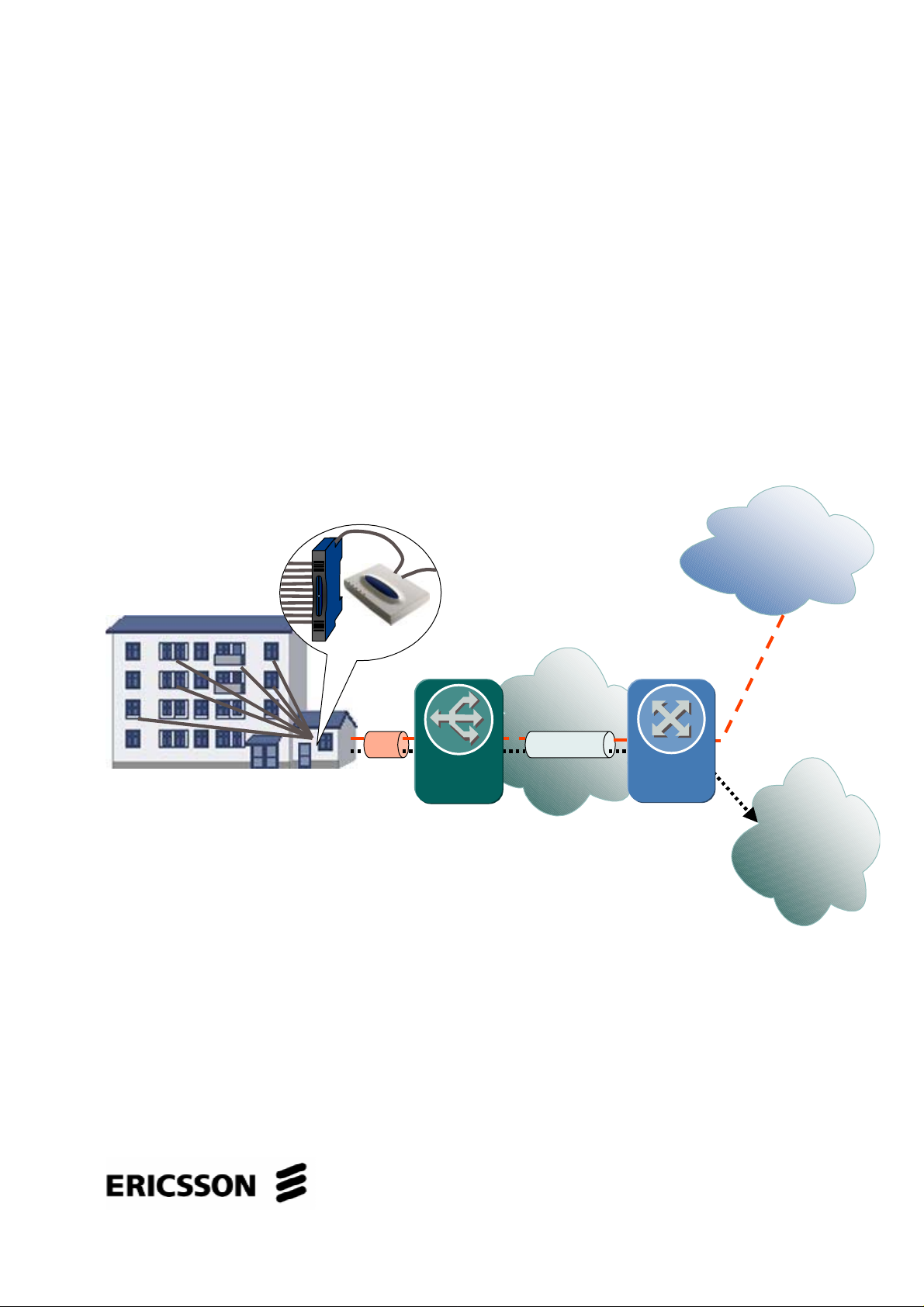
2.1 Shared DSL Concept
In a situation where another Access Provider owns the line to multi
dwellings, leasing a line for each End-user (subscriber) can be expensive.
The Shared DSL concept calls for leasing only one line, then creating a
remote EDA site. The connected End-users share the DSL line capacity,
while maintaining the EDA system security and benefits. For the Secondary
Access Provider, managing the remote site is almost the same as
managing nodes and End-users in a standard EDA network.
Figure 1 on page 2 illustrates the Shared DSL concept
Remote
Shared
Site
IP DSLAM
Secondary Access Provider
CPE Modem
Primary Access Provider
DSLAM
ADSL ADSLEth Any Carrier IP
Broadband
Network
Figure 1 Shared DSL Concept
Router/
BRAS
EDA
Network
Management
Traffic
Subscriber
Traffic
Data
Network
2
1/1553-HSC 901 86/1 Uen A 2006-02-21
Page 7

The Shared DSL Solution
The concept of the Shared DSL is using one DSL line inside the Primary
Access Provider network, terminating the line with a Customer Premises
Equipment (CPE) modem that converts the DSL to Ethernet. The Ethernet
is then converted again to DSL by the IP DSLAM to make the DSL
connection to the End-users (this part belongs to the secondary Access
Provider). The concept does not call for any specific equipment in the
Primary Access Provider network, except that it is able to separate and
isolate the data channels coming from the Shared DSL remote site: Enduser data and Management data.
The Concept allows for one type of Quality of Service for both End-users
and management traffic. The limiting factor is the capability of the CPE
modem in the remote site to prioritize traffic. Both types of traffic are
therefore best effort.
The End-user traffic is directed towards public data network (Internet) from
the Router or BRAS of the Primary Access Provider. The Management
traffic is directed toward the EDA network (Access Domain).
The Shared DSL solution requires that the used CPE Modem has the
capabilities of mapping between Ethernet VLANs and ATM Permanent
Virtual Circuits (PVCs).
The Shared DSL Solution supports DHCP option82 (please refer to System
Description for details about the DHCP relay agent in the EDA).
The Shared DSL solution does not support EDA Dynamic Management
VLAN concept (DMV).
1
1
The DMV is a solution for using a different management VLAN (not 246) in the EDA network, with
automatic adaptation of the IP DSLAMs to the management VLAN.
1/1553-HSC 901 86/1 Uen A 2006-02-21
3
Page 8

The Shared DSL Solution
2.2 Services
Up to seven services can be offered to the End-users of each remote site, if
the Primary Access Provider’s DSLAM and network supports it (eight PVCs
together with the Management channel). However, since there is no Quality
of Service differentiation between the different services, they can only be
used to enable End-users to use different Service Providers.
2.3 End-users Layer two Separation
It is most likely that all End-users of one remote site will be using the same
Service, and therefore the same VLAN in the remote site Ethernet. Layer
two separation of the End-users is achieved by using PPPoE, or by using
the EDA Fast forwarding feature that forwards all End-user traffic to a
specific router.
4
1/1553-HSC 901 86/1 Uen A 2006-02-21
Page 9

3 Router Role
The Router or BRAS plays an important role in the Shared DSL concept,
and must perform the following functions:
• DHCP requests from the IP DSLAM in the remote site must be relayed
towards the EDA network, using the management VLAN ID.
• The Management PVC from the remote site must be mapped to the
EDA Management VLAN.
• If PPPoE or PPPoA is used for the END-user traffic, it must be
terminated by the BRAS.
Router Role
• If the Router (or BRAS) is not an Edge Node of the EDA network as
well, a tunnel must be established to the EDN network (for example
L2TP or another VPN solution, see Figure 2 on page 5).
EDA
Network
Management
VLAN
EDA
Network
Broadband
Network
Management
PVC
Primary
Access Provider
Router/
BRAS
Router/
BRAS
Tunnel
Secondary
Access Provider
Broadband
Network
Management
PVC
Primary
Access Provider
Router/
BRAS
Management
VLAN
Secondary
Access Provider
Figure 2 Management Traffic Mapping
1/1553-HSC 901 86/1 Uen A 2006-02-21
5
Page 10

The Remote Site
4 The Remote Site
The Remote site is the extension of the EDA network. The Shared DSL
solution does not specify the full extent of the site, only the minimum
required functionality and basic elements.
4.1 Remote Site Elements
The remote site must contain at least the following elements:
• -48 VDC power supply
• 230 VAC outlet
• CPE modem
• EPN102 EDA Power Node
• IP DSLAM
• Necessary KRONE connectors for the IP DSLAM and EPN102
Depending on the type of installation and IP DSLAM used, an EDA filter
might also be necessary.
Note: Under usual circumstances, it is not necessary to have a battery
backup of the system, since the remote site is supplied with the
same power as the rest of the building.
6
1/1553-HSC 901 86/1 Uen A 2006-02-21
Page 11

The Remote Site
Figure 3 on page 7 illustrates a remote site for 12 End-users, using the
EDN312, which has a built-in filter.
Ethernet
Ethernet
& Power
ADSL &
telephony
to
End-users
EPN102EDN312
-48 VDC
Power Supply
Figure 3 Remote Site for 12 End-Users
CPE Modem
Subscriber Lines
To Central
Office
ADSL
from Central
Office
Adaptor
230 VAC
Mains outlet
1/1553-HSC 901 86/1 Uen A 2006-02-21
7
Page 12
The Remote Site
4.2 Environment
It is recommended to take some security measures for the site to prevent
tampering with the equipment (for example a locked cabinet).
The ambient temperature around the equipment must be within 0 – 45 ºC.
The relative humidity must be within 5% - 95%, non condensing.
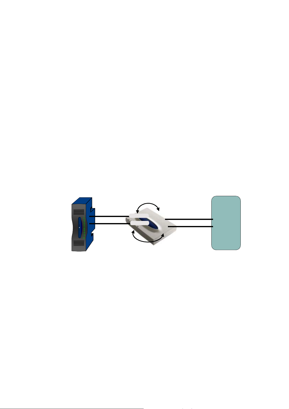
4.3 Configuring the CPE Modem
The CPE Modem must be configured to map the VLANs used by the IP
DSLAM to PVCs towards the Central Office (see Figure 4 on page 8). It
must be configured to use the PVCs (VPI, VCI) used by the Central Office
DSLAM, and the Management and Data VLAN IDs used by the IP DSLAM.
Central
Office
VLAN ID
VLAN ID
Management VLAN
Data VLAN
VLAN ID
VLAN ID
VPI / VCI
VPI / VCI
Management PVC
Data PVC
DSLAM
VPI / VCI
VPI / VCI
Figure 4 Configuration of the CPI Modem
Note: The Management VLAN ID does not necessarily have to be the
same VLAN ID as the ID used in the EDA network (although it is
recommended to use it to avoid confusion).
8
1/1553-HSC 901 86/1 Uen A 2006-02-21
Page 13

Acronyms and Abbreviations
Acronyms and Abbreviations
ADSL
Asymetric Digital Subscriber Line
ATM
Asynchronous Transfer Mode
BRAS
Broadband Remote Access Server
CPE
Customer Premises Equipment
DSL
Digital Subscriber Line
L2TP
Layer Two (2) Tunneling Protocol
PPPoA
Point to Point Protocol over ATM
PPPoE
Point to Point Protocol over Ethernet
PVC
Permanent Virtual Circuit
VCI
Virtual Channel Identifier
VPI
Virtual Path Identifier
VPN
Virtual Private Network
1/1553-HSC 901 86/1 Uen A 2006-02-21
9
Page 14

Ericsson AB
www.ericsson.com 1/1553-HSC 901 86/1 Uen A 2006-02-21
© Ericsson AB 2004, 2006 - All Rights Reserved
 Loading...