

Page 1

ECN330 and ECN320 User Guide
Page 2

ECN330 and ECN320 User Guide
.
Copyright
© Ericsson AB - 2005 All Rights Reserved
Disclaimer
No part of this document may be reproduced in any form without the written
permission of the copyright owner.
The contents of this document are subject to revision without notice due to
continued progress in methodology, design and manufacturing. Ericsson shall
have no liability for any error or damage of any kind resulting from the use of
this document.
Legal Notice
The Linux Core system is the operating system for the Ethernet Node Controller in ECN. The Linux distribution for ECN is based on standard open source
packages widely used in the Linux community. Please refer to the Third Party
License Agreements for the license terms.
Trademark List
Windows®
Windows NT®
Solaris®
Windows is a registered trademark of Microsoft
Corporation
Windows NT is a registered trademark of Microsoft
Corporation
Solaris is a registered trademark of Sun Microsystems, Inc.
1553-CNH 160 0787 Uen PA2 2005-09-23
ii
Page 3

.
Contents
1 Introduction to this Guide 1
1.1 Conventions 1
1.2 Revision History 2
1.2.1 This Revision 2
1.2.2 Version G 2
1.2.3 Version F 2
1.2.4 Version E 3
1.2.5 Version D 3
1.2.6 Version C 3
1.2.7 Version B 4
1.2.8 Version A 4
2 Introduction to the ECN 5
2.1 Topology of the EAN 6
2.2 Management of EAN 8
3 ECN Functions, Features and HW 9
3.1 Switching Unit Architecture and Features 10
3.1.1 Connections 10
3.1.2 Performance 11
3.1.3 PoE Ports 12
3.1.4 1000BASE-T RJ-45 and SFP Ports 13
3.2 Reserved VLANs, Interfaces and Ports Designation 15
3.3 LEDs User Interface 16
3.4 Power Supply Input Connector 18
3.5 Fan Tray 18
4 Maintenance 20
4.1 Replacing ECN 20
4.2 Replacing a Fuse 20
1553-CNH 160 0787 Uen PA2 2005-09-23 iii
Page 4

Error! No text of specified style in document.
4.3 Replacing a Fan Tray 21
5 Management Features Overview 23
5.1 Ethernet Access Node Alarms 24
5.2 Startup Failure 24
5.3 System Log 25
6 Description of the EAN 26
6.1 EAN in the Network 27
6.1.1 EAN Topologies 29
6.2 Line and Node Identification 34
6.3 Installation 38
7 Initial Configuration and Commissioning 39
7.1 The ECN Local Craft Tool 40
7.2 Installation of Software 40
8 Management from PEM 42
8.1 Discovering an EAN 42
8.1.1 Prerequisites 42
9 Web interface 43
9.1 Entering the Web Interface 43
9.2 System 43
9.3 Status 45
9.4 Configuration 51
9.5 Log 53
9.6 Test 55
10 Factory Defaults 57
11 Command Line Interface 58
11.1 Using the Console Connector 59
11.2 Using Telnet 60
iv 1553-CNH 160 0787 Uen A 2005-09-26
Page 5

Error! No text of specified style in document.
11.2.1 Running the ECN as an Switch 61
11.2.1.1 ECN330 Switch 61
11.2.1.2 ECN320/ESN310 Switch 62
11.2.2 Adding Switch Extensions to an EAN 63
11.2.2.1 ECN330 Switch Connected to an ECN 64
11.2.2.2 ECN320/ESN310 Switch Connected to an ECN 65
11.2.3 Adding more Switches to an EAN 66
11.3 Entering Commands 68
11.3.1 Keywords and Arguments 68
11.3.2 Minimum Abbreviation 68
11.3.3 Command Completion 69
11.3.4 Getting Help on Commands 69
11.3.5 Partial Keyword Lookup 70
11.3.6 Using Command History 70
11.3.7 Command Execution 70
11.3.8 Scripts 70
11.3.9 Special Commands 70
11.3.10 CLI Editing Keystrokes 71
11.4 Overview of CLI Commands 72
11.5 General Commands 73
11.5.1 end 73
11.5.2 exit 74
11.5.3 ping 74
11.5.4 rcli 75
11.5.5 restart 76
11.6 config 77
11.6.1 copy-dslport 78
11.6.2 dslport 78
11.6.2.1 alarm-thresholds 79
11.6.2.2 alarms 81
11.6.2.3 channel 81
11.6.2.4 line 83
11.6.2.5 performance-data 86
1553-CNH 160 0787 Uen A 2005-09-23
v
Page 6

Error! No text of specified style in document.
11.6.2.6 PVC commands 87
11.6.2.7 transmission-mode 97
11.6.3 ecn 98
11.6.3.1 inventory 99
11.6.3.2 link-aggregation 100
11.6.3.3 port 101
11.6.3.4 redundancy 107
11.6.3.5 spanning-tree 108
11.6.3.6 unmanaged-switch 115
11.6.3.7 ip 116
11.6.3.8 switch-extension 117
11.6.3.9 auto-rediscover 120
11.6.4 edn 121
11.6.4.1 link-configuration 121
11.6.5 esn 122
11.6.5.1 link-aggregation 122
11.6.5.2 port 123
11.6.5.3 spanning-tree 124
11.6.5.4 power-on-uplink 124
11.6.6 exn 125
11.6.6.1 line 126
11.6.6.2 packet-distribution 127
11.6.6.3 line-type 127
11.6.7 load-configuration 128
11.6.8 reset-dslports 129
11.6.9 save-configuration 130
11.6.10 system 130
11.6.10.1 aaa 131
11.6.10.2 backup-configuration 132
11.6.10.3 calendar 133
11.6.10.4 cli-autologout 133
11.6.10.5 install 134
11.6.10.6 interface 135
vi 1553-CNH 160 0787 Uen A 2005-09-26
Page 7

Error! No text of specified style in document.
11.6.10.7 local-management 137
11.6.10.8 ntp 138
11.6.10.9 password 140
11.6.10.10 pem-management 140
11.6.10.11 prompt 141
11.6.10.12 radius-server 142
11.6.10.13 restore-configuration 143
11.6.10.14 service-vlan 144
11.6.10.15 show 145
11.6.10.16 turn 146
11.6.10.17 update 147
11.6.10.18 vlan-unaware 147
11.7 led-test 149
11.7.1 led-test 149
11.8 show 150
11.8.1 dslport 150
11.8.2 ecn 151
11.8.3 edn 152
11.8.4 exn 152
11.8.5 esn 153
11.8.6 system 155
11.9 Fallback State CLI Commands 156
11.9.1 Commands 156
11.9.1.1 calendar 157
11.9.1.2 exit 157
11.9.1.3 interface 157
11.9.1.4 restart 157
11.9.1.5 update 158
11.9.1.6 show 158
11.9.1.7 clear 159
11.9.1.8 ping 160
12 Using a MIB Browser 161
1553-CNH 160 0787 Uen A 2005-09-23
vii
Page 8

Error! No text of specified style in document.
13 Troubleshooting 166
13.1 Diagnose Switch Indicators 166
13.2 Power and Cooling Problems 167
13.3 Embedded Nodes 167
13.4 CLI 168
14 Specifications and Technical Details 169
15 Programs Packages under the GNU Public License Terms 170
15.1 Kernel 170
15.2 Applications 171
15.3 Libraries 171
Glossary 172
Index 176
viii 1553-CNH 160 0787 Uen A 2005-09-26
Page 9

1 Introduction to this Guide
This guide describes the EDA Ethernet Controller Node ECN and is valid
for both the ECN330 and the ECN320. The term ECN refer to ECN320 and
ECN330. The term ECN switch refer to ECN320 and ECN330 in switch
mode. The term ECN320/ESN310 switch refer to ECN320 in switch mode.
When an ECN is illustrated in a figure, an ECN330 with an uplink port 27 is
used. The appearance of the ECN320 is the same just without this uplink
port.
The guide describes the concept, the hardware and the functionality. Furthermore, it provides an overview of software features, and detailed information on how to use the Command Line Interface (CLI) to configure the
ECN.
Introduction to this Guide
The guide is intended for both installation personnel and system administrators responsible for operating and maintaining network equipment.
The reader should have a basic knowledge of general switch functionality,
the Internet Protocol (IP), and Simple Network Management Protocol
(SNMP) in order to understand and utilize the information in the sections
describing the Command Line Interface (CLI) and management.
The guide does not attempt to give a complete explanation of the various
standards, but rather the implementation of the standards in the ECN. For a
more information of the standards, please refer to the standard specifications.
In order to fully understand the function and use of the ECN, it is recommended to read the System Overview and PEM User Guide.
The guide can be printed on a monochrome printer, but illustrations are
easier to understand if a color printer is used.
1.1 Conventions
The following conventions apply for textual instructions (not screen dumps):
ToolsÆOptions Means: Choose the Tools menu item, choose the Op-
tions menu item.
OK : A button in a GUI.
1553-CNH 160 0787 Uen PA2 2005-09-23
1
Page 10

Introduction to this Guide
Bold monospace letters mark text typed by the user (input) in Command Line Interface (CLI).
Regular monospace letters mark text output in CLI.
<ServerIP> is a parameter (argument) that should be replaced with the
actual value (for example, the IP address of a server). The <> symbols
must not be typed.
[argument] the brackets indicate that this argument is optional and can be
omitted. If used, the brackets must not be typed.
{argument1|argument2} means that either argument1 or argument 2
can be used as a value for this parameter.
1.2 Revision History
This guide is valid for EDA 2.2 RA1. Other product version, with functions
not described in this guide may be available.
1.2.1 This Revision
The Command Line Interface (CLI) is updated to reflect the command
structure.
1.2.2 Version G
The following changes were made:
• Minor textual connection added
• Added a section of how to run the ECN as a switch
1.2.3 Version F
The following has been changed:
• The EAN topologies have been revised. The ECN now supports the
FE-E1/T1 converter EXN104 and the ELN220 as embedded nodes.
• The ECN also supports daisy chaining of the optical switch ELN220
and the electrical switch ESN310.
• The ECN supports flexible service access.
2 1553-CNH 160 0787 Uen PA2 2005-09-23
Page 11

• The CLI commands have been revised and new commands have been
added in order to support the new topologies (embedded nodes, and
daisy chaining).
• Support of reverting an ECN to an ESN310 and back again.
1.2.4 Version E
The following has been changed:
• Support of ELN220 in an EAN is described
• Support of unaware VLAN in ECN from CLI is described
• Support of ECN auto completion on parameter added
Introduction to this Guide
• Change of password through the CLI added
• Correction of the CLI command link-configuration
• Minor corrections of illustrations
1.2.5 Version D
The following has been changed:
• Correction to the CLI command: link-configuration
• Minor textual corrections to sections 2, and 3.
• The section describing installation and upgrading of software has been
revised and moved.
• The sections have been slightly rearranged.
1.2.6 Version C
The following has been changed:
• The ECN has been supplied with dual power input ports
• The rear of the ECN has been supplied with two 20A fuses, one for
each power input
• The ECN has been supplied with an uplink 100 Base-FX option
1553-CNH 160 0787 Uen PA2 2005-09-23
3
Page 12

Introduction to this Guide
• The web interface has been changed with new layout
• New CLI structure and layout
• New CLI commands have been added
1.2.7 Version B
The following has been changed:
• Upgrading SW description is moved to ECN330 Installation Guide or
ECN320 Installation Guide.
• Replacing ECN added
• Service VLANs are supported and configured by PEM
• No special attention should be paid when connecting ESN108
1.2.8 Version A
The first version of the guide.
4 1553-CNH 160 0787 Uen PA2 2005-09-23
Page 13

2 Introduction to the ECN
The ECN is composed of two main components: The Ethernet Node Con-
troller (ENC), and a 24 ports Ethernet switch with Power over Ethernet
(PoE) capabilities. The Ethernet Controller Node (ECN) is a unit that controls and aggregates other EDA nodes (embedded nodes). Together, the
ECN and the embedded nodes constitute a logical node – the Ethernet Access Node (EAN). The EAN is managed as a single node.
The EAN can be configured in several ways depending on the type and
number of the embedded nodes connected to the ECN.
The following EDA nodes can be used as embedded nodes (for further detail refer to section
6 on page 26):
Introduction to the ECN
• IP DSLAMs (EDN110 and EDN312)
• ESN108 switch,
• Optical ELN220 switch
• EXN104 FE to E1/T1 converter
• ESN310
• ECN320/ESN310 switch
• ECN330 switch
Other 3
rd
party unmanaged switches can also be used in the EAN, but the
following sections primarily focus on the EAN with the EDA nodes listed
above.
The software in the ECN contains the EDA Management Proxy (EMP). The
means that there is no dependency on the Access Domain Server during
start-up or restart. The EAN is completely autonomous and self-sustained,
as the Access Domain Server functions are hosted by the ECN, see
1 on page
6.
Figure
The EAN can be managed without PEM using the Command Line Interface
of the ECN. This is described later in this guide.
All embedded elements are Plug and Play, with automatic registration in
PEM. The EAN elements may be placed in one cabinet, appearing physically as a single node, or distributed in different sites on different locations.
1553-CNH 160 0787 Uen PA2 2005-09-23
5
Page 14

Introduction to the ECN
For Information about the ECN330-switch refer to ECN330-switch User’s
Guide. For Information about the ECN320/ESN310 switch refer to ECN320
User Guide
2.1 Topology of the EAN
Depending on how the topology of the EAN is designed, based on the
nodes described above, the supported number of end-users may vary.
Below in
Figure 1 on page 6 an example of how the topology of an EAN
can be designed is shown with IP DSLAMs connected either directly to the
ECN or through the 8-port switch ESN108.
Fully extended with ESN108 switches on all 24 ports of the ECN and eight
12-ports IP DSLAMs on all ports of the ESN108 will enable the EAN to
support 2304 end-users.
Another realization of the EAN is the EDN288, which is a pre-cabled solution, delivered in a subrack. The EDN288 contains one ECN with the 12line IP DSLAM (EDN312) connected to all 24 ports, and thus supports 288
end-users. For a more detailed description of this specific EAN please see
the EDN288 User Guide and the EDN288 Installation Guide.
PEM
Ethernet Acce ss Node
ECN
FTP
Ethernet
Management
Proxy
DHCP
TFTP
SNTP
Alarm
ConfigSW
ESN108
(optional)
EDNXXX
Towards
broadband
backbone
Figure 1 The EAN with ESN108 and IP DSLAMs
6 1553-CNH 160 0787 Uen PA2 2005-09-23
Page 15

Introduction to the ECN
The EAN topology is described in more details in section 6.1 on page 27,
where examples using the ELN220 optical switch, the ESN310 switch and
the EXN104 FE to E1 converter are discussed.
1553-CNH 160 0787 Uen PA2 2005-09-23
7
Page 16

Introduction to the ECN
2.2 Management of EAN
The EAN can be installed and configured for site verification without connection to PEM.
During normal operation, if the connection from PEM to the EAN is lost,
traffic to and from the end-users will continue, and it will only be possible to
change the end-user parameters as for example the line speed. The EAN
will continue to run in local mode, which means that the ECN starts acting
as a stand-alone Domain Server using the last valid configuration and SW
in order to continue operation.
If any configuration changes (for the EAN) are made in PEM while the EAN
is not reachable, the EAN will have to be synchronized manually from PEM
when the connection is restored.
The Command Line Interface (CLI) of the ECN makes it possible to run the
EAN without connection to PEM, that is, use the CLI for management, configuration and for DSL line provisioning. For full management configuration
PEM must be used.
8 1553-CNH 160 0787 Uen PA2 2005-09-23
Page 17
ECN Functions, Features and HW
3 ECN Functions, Features and HW
The following sections describe the ECN functions, features and hardware.
The ECN is used as the first and second level aggregation switch in the
EDA network, while also supplying directly connected IP DSLAMs with DC
power over the Ethernet connections.
As well as its Power-over-Ethernet capabilities, the ECN provides comprehensive network management features, such as multicast switching, virtual
LANs, and Layer 2 Quality of Services (QoS), which provide reliability and
consistent performance for network traffic.
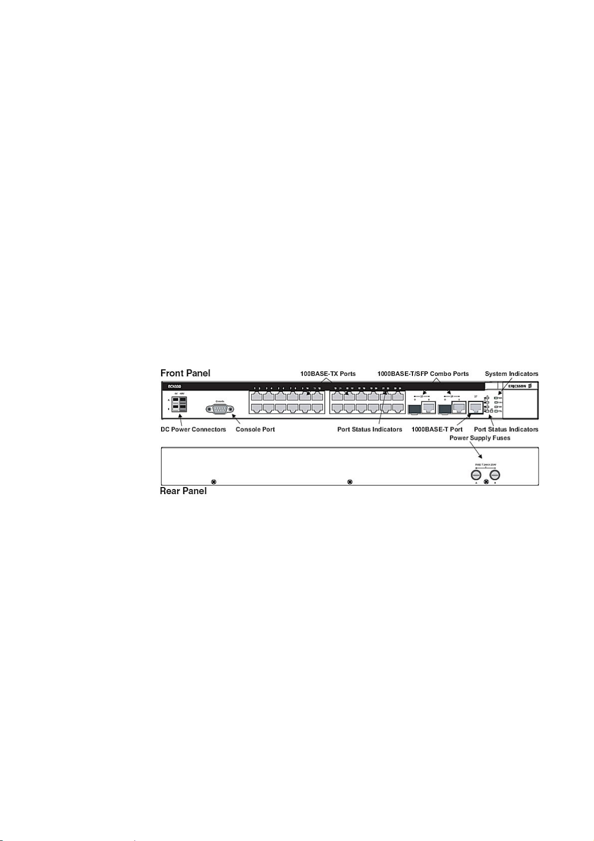
front and rear panels of the ECN (ECN330).
Figure 2 on page 9 shows the
Figure 2 ECN330 Front and Rear Panels
1553-CNH 160 0787 Uen PA2 2005-09-23
9
Page 18

ECN Functions, Features and HW
3.1 Switching Unit Architecture and Features
The ECN employs a wire-speed, non-blocking switching fabric.
This permits simultaneous wire-speed transport of multiple packets at low
latency on all ports. The ECN also features full-duplex capability on all
ports, which effectively doubles the bandwidth of each connection.
Auto-negotiation is used to select the optimal transmission speed and
communication mode for each connection. With store-and-forward switching and flow control, maximum data integrity is always maintained, even
when the loading is heavy.
3.1.1 Connections
The ECN includes two uplink combo 1000BASE-T/SFP ports on the front
panel. Optional slide-in SFP transceivers can provide 100 Mpbs (100BASEFX) and 1000 Mbps (1000BASE-SX, 1000BASE-LX, 1000BASE-LH) fiber
links to remote devices. This is utilized in the ELN220 scenario described in
the introduction of this guide.
The ECN330 also contains one independent 1000BASE-T RJ45 port (Port
27) that operates at 10 Mbps or 100 Mbps, half or full duplex, or at 1000
Mbps, full duplex.
The ECN has 24 10BASE-T/100BASE-TX RJ-45 ports. The features of the
ports are summarized below:
• 24 dual-speed ports for 10 or 100 Mbps Ethernet connections, with
support for automatic MDI/MDI-X. All 10/100 RJ-45 ports support
Power-over-Ethernet (PoE)
• Two Gigabit combo ports—use either 10/100/1000BASE-T RJ-45 or
Small Form Factor Pluggable (SFP) transceiver slot (100 Mbps and
1000 Mbps)
• One independent 10/100/1000BASE-T Gigabit Ethernet port
• Auto-negotiation enables each RJ-45 port to automatically select the
optimum communication mode (half or full duplex) for the attached device
• Unshielded (UTP) cable supported on all RJ-45 ports: Category 3 or
better for 10 Mbps connections, Category 5 or better for 100 Mbps
connections, and Category 5, 5e, or 6 for 1000 Mbps connections
• IEEE 802.3u, IEEE 802.3z, and IEEE 802.3ab compliant
10 1553-CNH 160 0787 Uen PA2 2005-09-23
Page 19

3.1.2 Performance
• Transparent bridging – The ECN supports IEEE 802.1D transparent
bridging. The address table facilitates data switching by learning addresses, and then filtering or forwarding traffic based on this information. The address table supports up to 8K and 16K addresses
(ECN320/ECN330).
• Store-and-Forward Switching – The ECN copies each frame into its
memory before forwarding them to another port. This ensures that all
frames have a standard Ethernet size and have been verified for accuracy with the cyclic redundancy check (CRC), thus preventing bad
frames from entering the network and wasting bandwidth. To avoid
dropping frames on congested ports, the ECN provides 32 Mbytes for
frame buffering. This buffer can queue packets awaiting transmission
on congested networks.
ECN Functions, Features and HW
• Aggregate bandwidth up to 8.8 Gbps for ECN320 and 10.8 GBPS for
ECN330.
• Packet capacity 8.9 Mpps (million packets per second)
• Filtering and forwarding at line speed
• Broadcast storm control - Broadcast suppression prevents broadcast
traffic from overwhelming the network. When enabled on a port, the
level of broadcast traffic passing through the port is restricted. If broadcast traffic rises above a predefined threshold, it will be throttled down
until the level falls back beneath the threshold.
• The ECN supports up to 4094/250 (ECN330/ECN320) tagged Service
VLANs (VLANs used for End-user traffic) based on the IEEE 802.1Q
standard. Service VLANs can be assigned using CLI and PEM. Assigning a VLAN from the CLI configures the VLAN on all ports.
• Quality of Service (QoS) supports four levels of priority. The ECN prioritizes each packet based on the required level of service, using four priority queues with strict priority and using IEEE 802.1p and 802.1Q tags
to prioritize incoming traffic. These functions can be used to provide independent priorities for delay-sensitive data and best-effort data.
• Multicast Switching based on IGMP Snooping
• Link redundancy supported by utilizing Rapid Spanning Tree (RSTP).
• Link aggregation by utilizing LACP
1553-CNH 160 0787 Uen PA2 2005-09-23
11
Page 20

ECN Functions, Features and HW
3.1.3 PoE Ports
All of the 24 10BASE-T/100BASE-TX RJ-45 ports support PoE capability
and can supply up to 23.1 W of power to connected EDA nodes.
The PoE enables DC power to be supplied to the connected nodes through
the Ethernet cable. IP DSLAMs attached to a port can directly draw power
from the ECN over the Ethernet cable without requiring a separate power
source. The ECN automatically detects an EDA node by its authenticated
PoE signature and senses its required load before turning on DC power to
the port. An electrical port of ESN108 (which is also a PoE node) can also
be connected to the ECN. The sense circuit in both nodes (ECN and
ESN108) will sense that no power is required. This detection mechanism
also prevents damage to other network equipment that is not an EDA node.
The ECN delivers power to the IP DSLAM using the two wire pairs in UTP
or STP CAT 5 cable that are not used for 10BASE-T/100BASE-TX connections (for details see ECN330-switch User’s Guide). Each line is individually
controlled with an auto-detect circuit that opens up if a load within the EDAspecified range is detected, and shuts down if the load exceeds the limit of
23.1 W. Each line is filtered for surge currents and has a 4 ms backup reservoir, should short voltage dropouts occur.
The ECN can provide up to 600 mA continuously on each 10/100 Mbps
port, or up to 23.1 W of power. However, taking into account some power
loss over the cable, the amount of power that can be delivered to an EDA
node is about 21 W. If a device draws more than 625 mA from a port, an
overload condition occurs and the port turns off the power.
These ports also support automatic MDI/MDI-X operation, so straightthrough cables can be used for all network connections to PCs or servers,
or to other switches or hubs.
The ports also support auto-negotiation, so the optimal transmission mode
(half or full duplex), and data rate (10 or 100 Mbps) can be selected automatically, if this feature is also supported by the attached device. If a device
connected to one of these ports does not support auto-negotiation, the correct speed will be sensed by the port, but the transmission mode will by default be half duplex. Each port also supports auto-negotiation of flow control, so the ECN can automatically prevent port buffers from becoming saturated.
The ECN controls the power and data on a port independently. Power can
be requested from a device that already has a data link to the ECN. In addition, the ECN can supply power to a device even if the port’s data connection has been disabled. The power on a port is continuously monitored by
the ECN and it will be turned off as soon as a device connection is removed
12 1553-CNH 160 0787 Uen PA2 2005-09-23
Page 21

3.1.4 1000BASE-T RJ-45 and SFP Ports
There are two combo Gigabit RJ-45 ports with shared Small Form Factor
Pluggable (SFP) transceiver slots. If an SFP transceiver is installed (refer to
the ECN330 Installation Guide or ECN320 Installation guide) in a slot and
has a valid link on the port, the associated RJ-45 port is disabled.
The 10/100/1000BASE-T RJ-45 ports support automatic MDI/MDI-X operation, so straight-through cables can be used for all network connections to
PCs or servers, or to other switches or hubs.
Note: The 10/100/1000BASE-T RJ-45 ports do not support PoE capabil-
ity.
SFP is a new specification for compact, modular transceivers that are hot
swappable. The SFP slots support 100BASE-FX and 1000BASE-SX,
1000BASE-LX, or 1000BASE-LH transceivers for fiber optic connections to
remote devices.
ECN Functions, Features and HW
The ECN330 also contains one independent 1000BASE-T RJ45 port (Port
27) that operates at 10 Mbps or 100 Mbps, half or full duplex, or at 1000
Mbps, full duplex. Because all of the Gigabit RJ45 ports support automatic
MDI/MDI-X operation, straight-through cables can be used for all network
connections to PCs or servers, or to other switches or hubs.
Each single-mode fiber optic port requires 9/125 micron single-mode fiber
optic cabling with an optical connector. Each multimode fiber optic port requires 50/ 125 or 62.5/125 micron multimode fiber optic cabling with an optical connector.
Warning!
This ECN uses lasers to transmit signals over fiber optic cable. The lasers
are compliant with the requirements of a Class 1 Laser Product and are
inherently eye safe in normal operation. However, never look directly at a
transmission port when it is powered on.
To connect a fiber to the SFP:
1. Check that the fiber terminators are clean. Wiping them gently with a
clean tissue or cotton ball moistened with a little ethanol can clean Cable plugs. Dirty fiber terminators on fiber optic cables will impair the
1553-CNH 160 0787 Uen PA2 2005-09-23
13
Page 22
ECN Functions, Features and HW
quality of the light transmitted through the cable and lead to degraded
performance on the port.
2. Connect one end of the cable to the optical port on the ECN and the
other end to the optical port on the other device. Since optical connectors are keyed, the cable can be attached in only one orientation.
LC fiber
connector
Figure 3 Making Optical Port Connections
3. As a connection is made, check the LED on the ECN’s front panel for
the corresponding module to be sure that the connection is valid.
Note: SFP transceivers are hot-swappable. The ECN does not need to
be powered off before installing or removing a transceiver. However, always first disconnect the network cable before removing a
transceiver.
14 1553-CNH 160 0787 Uen PA2 2005-09-23
Page 23

ECN Functions, Features and HW
3.2 Reserved VLANs, Interfaces and Ports Designation
Since the ECN acts as a Network Address Translator (NAT) for management traffic connecting and hiding the embedded nodes from the Access
Domain Management, different interfaces (each interface is configured independently) are utilized:
Internal Interface – This interface is the gateway for the embedded nodes.
It has an internal IP Address of the ECN, and uses the internal management VLAN.
• External Interface – This interface represents the EAN to the outside
network. It has the IP Address of the ECN, and uses the management
VLAN used in the EDA network.
• Internal Interface Untagged – This interface is used to enable Dy-
namic Management VLAN (DMV). This feature ensures that embedded
nodes will be automatically reconfigured if their configured management VLAN is not the same as the internal VLAN in the EAN (for example if an IP DSLAM that was connected directly to the EDA network
using VLAN id 246, is connected as an embedded node using VLAN id
247). For more information about the DMV, refer the Management
VLAN Configuration Guide. Note that the ECN does not have to be
configured for the DMV. It automatically supports the DMV for all embedded nodes.
There are two types of ports in the ECN: Uplink ports (ECN320: 25 and 26,
ECN330: 25,26 and 27) and Downlink ports (1 – 24):
• Uplink ports are automatically configured with the External manage-
ment VLAN id (default 246). Any untagged traffic entering an uplink
port is tagged with VLAN id 1 and discarded, since the data will not be
forwarded to any port.
• Downlink ports are configured automatically with the Internal man-
agement VLAN id (default 247). Any untagged traffic entering a
downlink port is tagged with the Untagged VLAN id (default 248). The
embedded nodes can use untagged frames to get information about
the used management VLAN.
Apart from the mentioned VLANs, the EAN also uses VLAN id 4093 internally.
1553-CNH 160 0787 Uen PA2 2005-09-23
15
Page 24

ECN Functions, Features and HW
3.3 LEDs User Interface
The unit also includes a display panel for key system and port indications
that simplify installation and network troubleshooting. The LEDs, which are
located on the front panel for easy viewing, are shown in
16 and described in Table 1 on page 17.
Figure 4 on page
Figure 4 System and Port Status LEDs
16 1553-CNH 160 0787 Uen PA2 2005-09-23
Page 25

ECN Functions, Features and HW
Table 1 System and Port Status LEDs
LED Condition Status
System Status
On Green The unit’s internal power supply is operating normally. PWR
Off The unit has no power connected.
DIAG
On Green The system diagnostic test has completed successfully.
Flashing
Green
On Red The system diagnostic test has detected a fault in the
On Red One or both cooling fans have failed. FAN
Off The unit’s cooling fans are operating normally.
CTRL
Flashing
Green (fast)
On Green ENC in normal operation
On Red Error in ENC (Fallback state and when booting)
Off ENC not present
10/100 Mbps Ports
1 ~24
(Link/Activity)
On or Flash-
ing Green
Flashing
Red
The system diagnostic test is in progress.
Switching unit.
ENC self test and boot in progress
(during start)
Port has established a valid 10 or 100 Mbps network
connection. Flashing indicates activity.
Port has detected a power overload or short circuit and
has shut down the power on the port.
Off There is no valid link on the port.
100/1000 Mbps Combo Ports
25, 26
(E - RJ-45),
On or Flash-
ing Green
(O - SFP)
Off There is no valid link on the port.
10/100/1000 Mbps Ports
Port 27
(Link/Activity)
On or Flash-
ing Green
Off There is no valid link on the port.
1553-CNH 160 0787 Uen PA2 2005-09-23
Port has established a valid 10, 100, or 1000 Mbps
network connection. Flashing indicates activity.
Port has established a valid 10, 100, or 1000 Mbps
network connection. Flashing indicates activity.
17
Page 26
ECN Functions, Features and HW
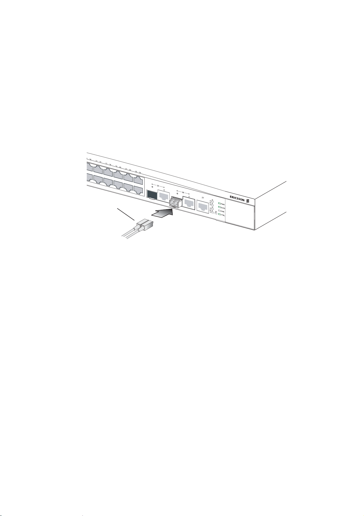
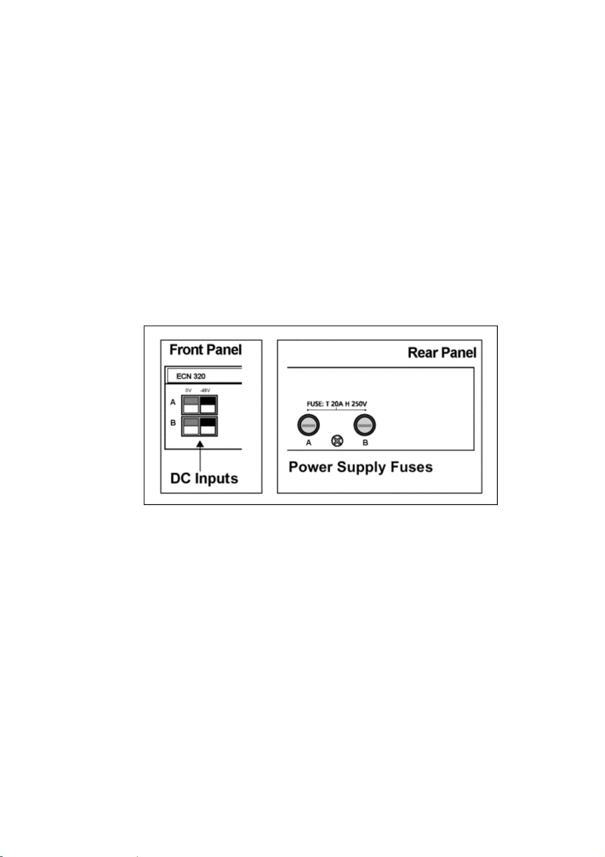
3.4 Power Supply Input Connector
The ECN has a dual power input with the purpose of achieving redundancy.
The power will be supplied by both power inputs.
If one of the power supplies is out of order for some reason the other supply will automatically take over without any disturbances.
The power supply input connector is located on the front panel of the ECN,
see
Figure 5 on page 18.
The standard power supply for the ECN is -48 VDC, which includes protection through a disposable fuse (located on the rear panel).
Figure 5 Power Supply Input Connector and Fuse
3.5 Fan Tray
The ECN contains one removable fan tray located behind a front-panel access cover on the right side of the unit, see
tray includes two fans for cooling the ECN. A front-panel LED indicates if
one or both fans have failed, in which case, the fan tray should be replaced.
Figure 6 on page 19. The fan
18 1553-CNH 160 0787 Uen PA2 2005-09-23
Page 27

ECN Functions, Features and HW
Figure 6 Fan Tray
1553-CNH 160 0787 Uen PA2 2005-09-23
19
Page 28

Maintenance
4 Maintenance
4.1 Replacing ECN
The ECN is uniquely identified in PEM by its MAC address. After replacing
the HW, the MAC address of the new ECN must be registered in PEM. It is
vital when replacing an ECN that no embedded nodes are changed until
the registration is completed. To replace an ECN:
1. Disconnect the power and Ethernet connections from the ECN. The
Ethernet connection must be marked, so they can be reconnected to
the same port number in the new HW.
2. Dismount the old ECN.
3. Mount the new ECN.
4. Connect the power and perform the basic configuration according to
the instruction in the ECN330 Installation Manual or ECN320 Installa-
tion Manual. Note that the IP address of the new node must be the
same as the old one.
5. Connect the Ethernet cables to the ECN.
6. Update the SW if needed (from PEM).
7. Possible restore of configuration information from a backup file.
8. Make a Forced Synchronization from PEM (button in the EAN proper-
ties, in the Network Configuration Manager). This action will update the
PEM database with the MAC address of the new node, and download
the configuration to all the embedded nodes.
9. The replacement is complete.
Note: An ECN330 must be replaced with an ECN330 and not an
ECN320. An ECN320 cannot be replaced with an ECN330 but only
with an ECN320.
4.2 Replacing a Fuse
The fuse protecting the ECN’s DC power supply is disposable. If the fuse
has blown, replace it with a new 20 A, 250V type T fuse.
20 1553-CNH 160 0787 Uen PA2 2005-09-23
Page 29

Maintenance
Warning!
First power off the ECN before replacing a DC power supply fuse.
To replace a fuse, follow these steps:
1. Remove the -48 VDC power source from the ECN.
2. Unscrew the fuse holder counter-clockwise from its socket. Pull out the
blown fuse and discard it.
3. Insert a new 20 A, 250V fuse into the fuse holder and then screw the
holder clockwise back into the fuse socket.
4. Reconnect the -48 VDC power source to the ECN.
4.3 Replacing a Fan Tray
The fan tray should be replaced if the FAN status LED turns on red (a cooling fan in the fan tray has failed).
Caution!
To ensure proper cooling of the ECN, both fans must be operational. If one
fan fails the ECN will continue to run, but the fan tray should be replaced
as soon as possible.
The ECN’s fan tray can be completely removed without powering off the
unit.
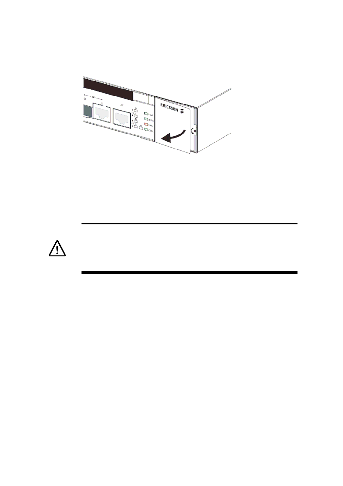
To replace a fan tray, follow these steps:
1. Remove the fan tray plastic access cover on the right side of the ECN’s
front panel by pulling the cover’s right edge out, until it becomes free.
1553-CNH 160 0787 Uen PA2 2005-09-23
21
Page 30
Maintenance
Figure 7 Fan Tray Access
2. Unscrew the fan tray’s screw.
3. Grasp the fan-tray’s handle and pull it outward to disconnect it from the
ECN. Carefully slide the fan tray out of the ECN.
Caution!
The new Fan tray must be inserted immediately after the old one is removed.
4. Install a new fan tray in the ECN by sliding it back into the empty slot.
Push in firmly so that the fan tray’s connector is fully engaged with the
ECN.
5. Screw and tighten the fan tray’s screw.
6. Check that the FAN status LED on the ECN front panel is off and that
both new fans are running.
7. Replace the fan tray plastic access cover on the ECN front panel by
pushing the cover’s right edge in until it snaps into place.
22 1553-CNH 160 0787 Uen PA2 2005-09-23
Page 31

Management Features Overview
5 Management Features Overview
The ECN includes a management agent that enables the features listed in
this guide to be configured and monitored using CLI or through SNMP applications.
The following management interfaces is supplied:
• LEDs for “at-a-glance” visual monitoring of network and port status,
see section
• Command Line Interface (CLI) - Direct connection to the RS-232
console port or by connecting to the switch through a network connection using Telnet or network management software
3.3 on page 16.
• SNMP – using SNMP applications
• HTTP - An additional HTTP server enables remote monitoring of
the ECN, using any Internet Browser, see
Figure 8 on page 23.
The IP address of the ECN is static only, and must be configured from the
local console connector using the ECN Local Craft Tool, see section
page
40.
Local Visual monitoring
CLI
(ECN320 Local
Craft Tool)
CLI (Telnet) SNMP HTTP
7.1 on
Figure 8 Management of the ECN
The different management methods offer different features. Complete
management and monitoring is only available through SNMP. The CLI is
used for configuration, and the HTTP is used for easy remote monitoring.
All management options (except visual monitoring) require a User name
and Password (community for SNMP) before the ECN management can be
accessed.
1553-CNH 160 0787 Uen PA2 2005-09-23
23
Page 32

Management Features Overview
5.1 Ethernet Access Node Alarms
Alarms (SNMP traps, notifications or informs) from the EAN are sent to the
IP address of the Trap Receiver. The traps are always sent with the IP address of the ECN (which is the only address known in the network) as the
sender address. However, the traps contain the identification of the embedded node as a parameter, thus enabling easy and fast identification of
the embedded node that originating the alarm. The identification of the
nodes complies with the identification concept shown in
34. In Figure 9 on page 24 an alarm received from the EAN is shown. The
alarm states the EAN is based on the ECN with the IP address
172.30.59.12. The alarm also states that the element on port 1 is unreachable.
Figure 15 on page
Figure 9 Alarms from the EAN
5.2 Startup Failure
If for some reason (for example a corrupt application) the ECN fails to start,
it will switch to a Fallback state. The Fallback state is an emergency application, which contains a limited CLI that enables diagnostics and reloading
of software. When the ECN is in Fallback state, only the CLI can be used
as management interface. The normal PEM control (which is SNMP based)
is not possible. Only the Console connector on the ECN or Telnet can be
used. (whether Telnet can be used depends on the reason for the Fallback
state).
24 1553-CNH 160 0787 Uen PA2 2005-09-23
Page 33

5.3 System Log
The ECN keeps a log of events and errors by using Sys log. There are two
log files, one for errors and one for all events (inclusive errors). Each log file
can be up to 500 KB. When the size of a log file reaches 500 KB, the file is
cleared. The events log file (detailed) is also cleared on each restart. The
log files can be viewed using the CLI if the ECN is in Fallback state, or using a Web browser in normal operation, see section
might take a while to write the log.
Management Features Overview
9.5 on page 53. It
1553-CNH 160 0787 Uen PA2 2005-09-23
25
Page 34

Description of the EAN
6 Description of the EAN
As described in the introduction the ECN is the key element in the EAN.
Several nodes can be connected to the ECN (see section
2 on page 5):
The nodes can be combined in various ways to form an EAN.
26 illustrates the logical structure of the management and subscriber
page
Figure 10 on
traffic in the EAN.
A logical structure in this context means that the EAN does not necessarily
contain all the elements. The basic topologies supported by the EDA system are described in more details in this section.
PEM
ECN
Ethernet Node Controller
ELN220 ESN310
ESN108
EDNxxx
EDNxxx
Embedded Nodes
EMP
ESN108
EDNxxx
Legend:
EAN
Management:
EAN Internal
Management:
Subscriber
Traffic:
Switching Unit
EXN104
EXN104
EDNxxx
ESN108
EDNxxx
Ethernet Access Node
Figure 10 Ethernet Access Node Structure
The Ethernet Node Controller (ENC) manages all the embedded nodes.
From a management point of view, the switching unit is also an embedded
node, even though it is located and integrated in the ECN.
The ENC is the only element communicating directly with the Public
Ethernet Manager (PEM). Using the EDA Management Proxy (EMP) function, the ENC forwards the communication to and from the embedded
26 1553-CNH 160 0787 Uen PA2 2005-09-23
Page 35

Description of the EAN
nodes. Note that only the management traffic is going through the ENC.
The end-user traffic is unaffected by the EAN structure.
The ENC assumes all the functions of the Access Domain Server for the
embedded nodes. However, the Access Domain Server must be running
for the following reasons:
1. All communication with the ECN is SNMP based, and therefore goes
through the Domain Service, which is installed on the Access Domain
Server.
2. The ENC receives new SW applications for the ECN from the Domain
File Server when a SW upgrade is performed, and the Domain File
Server is located on the Domain Server.
3. The ENC receives SW applications and configurations for the embedded nodes from the Domain File Server when the EAN is synchronized
from PEM.
Note: Only the following nodes are supported as embedded nodes in this
release: EDN110, EDN312, ESN108, ELN220, EXN104, ESN310
and ECN switch.
The ECN is connected as an Ethernet switch, aggregating the IP DSLAMs,
Figure 11 on page 29. All the connections between the ECN and the
see
embedded nodes are normal Ethernet connections (with or without PoE).
Management traffic between PEM and ECN is directed to the EDA management VLAN. However, the management traffic between the ECN and
the embedded nodes is directed to an internal EAN management VLAN.
The EAN internal management VLAN is (and must be) a different VLAN
from the EDA management VLAN in order to separate the two logical networks. Two different Ethernet Access Nodes may use the same VLAN id
for the internal management traffic. This will have no consequence, since
this VLAN is not visible for the rest of the network, outside the EAN. Apart
from the internal management VLAN, other VLANs are reserved for internal
use of the EAN.
End-user traffic must not be directed to any of the reserved VLANs. The
VLAN issue is discussed in more details in section
3.2 on page 15.
6.1 EAN in the Network
The topology of the EDA network based on the EAN can be designed in
various ways using the EDA nodes listed below:
• ECN – The 24 port Ethernet Controller Node
1553-CNH 160 0787 Uen PA2 2005-09-23
27
Page 36

Description of the EAN
• ESN108 – 8 port switch
• ELN220 – 24 optical switch
• ESN310 – 24 port switch
• ECN320/ESN310
• ECN330 switch
• EXN104 – FE to E1/T1 converter
• EDN312 and EDN110 – IP DSLAMS with 12 and 10 lines
• EPN102 – The Ethernet Power Node used together with the remote
EXN104
An access domain consist of more EANs as well as stand-alone IP
DSLAMs connected to for example an ESN310 switch.
The embedded nodes of the EAN are not shown, when the network topolgy
or inventory is viewed in the HP OpenView NNM or the PEM application
Network Configuration Manager (NCM). For example viewing the network
shown in
Figure 11 on page 29, will show only four elements: one EDN110,
one ESN310 and two EANs. Alarms coming from an embedded node will
be seen as if they come from the EAN (though identifying the embedded
node).
Viewing an EAN in the Status Manager in PEM will show all the embedded
nodes: ECN, a number of ESN108 and a number of IP DSLAMs and so on.
The status of each embedded node can be inspected, including single
ADSL lines status and properties.
The EDA System in
Figure 11 on page 29 shows two EANs and a standalone solution based on the ESN310 switch. The EAN to the right shows a
combination of the ECN and the 8-port switch ESN108. Each ESN108 has
up to 8 IP DSLAMs, as for example the EDN312 IP DSLAMs. The EAN to
the left shows the IP DSLAMs connected directly to the ECN.
The topology is discussed in more details in the sections below.
28 1553-CNH 160 0787 Uen PA2 2005-09-23
Page 37

Description of the EAN
Topology
&
Inventory
EDA Management VLAN
Ethernet
Access Domain
Domain Server
NCM
NNM
Status
+
Alarms
Ethernet Access Node
EAN VLAN
Manager
Legend:
Ethernet connec t i on
ADSL connection
Figure 11 The Ethernet Access Node in the Network
6.1.1 EAN Topologies
The following sections describe a series of topology scenarios supported in
this release of the EDA system.
ESN310
ECN
2ndlevel
Aggregation Switch
Ethernet Access Node
ECN
EAN VLAN
ESN108 ESN108
Figure 12 on page 31 the topologies based on ELN220 is illustrated.
In
The Ethernet Access Node (EAN) can be composed of an ECN with any of
the configuration 1 to 6 connected to the downlink ports.
Furthermore up to three of the 24-port optical switch ELN220 can be con-
nected to the optical port 25 or 26 of the ECN. This is also called switchextension, daisy chaining or switch stacking and is configured by the Command Line Interface (CLI) of the ECN. The switches are connected through
the uplink ports. The first switch is connected to one of the uplink ports on
the ECN that is either port 25 or 26. Port 27 on ECN330 must not be used.
In order to add the ELN220 switch it must be configured with the correct IP
address, internal management VLAN and with VLAN transparency. Other
configuration is also necessary: SNMP alarm receiver, alarm type, NTP
server. When the first switch-extension is added, the VLAN configuration of
the specified uplink port on the ECN switch will be changed in order to allow traffic on the internal VLAN instead of public, external or managed
1553-CNH 160 0787 Uen PA2 2005-09-23
29
Page 38

Description of the EAN
VLAN. The port is re-configurred to allow public, external or managed
VLAN when the last switch-extension is removed.
The IP DSLAM can be connected to the ELN220 through the optical uplink
port of the ESN108 switch.
The Fast Ethernet (FE) to E1/T1 converter can be used to install EDA at
small remote sites through the E1 or T1 lines.
All the nodes are managed by the ECN as embedded nodes.
The 6 combinations of embedded nodes shown in the illustration can be
connected to any port of the ECN. The EXN104 converter on the remote
site will in some cases (2, 4 and 6) need a power node to supply the necessary power. The power node EPN102 is illustrated below. When the
ESN108 switch is used remotely to aggregate the EXN104 converter (combination 6) it can supply both the upstream and downstream converters
with power through the Ethernet cables. As indicated below the ESN108 is
connected to the uplink EXN104 through the electrical port 8, which must
be configured in the ESN108 in order to supply power through the uplink
port 8. The configuration is done through the command line interface of the
ESN108 or the ECN.
Note: Please note that the EDA 2.2 R1A release does not support daisy
chaining a mixture of ELN220 and ESN310.
30 1553-CNH 160 0787 Uen PA2 2005-09-23
Page 39

Description of the EAN
Connect any of t he com binations: *
1 2 3 4 5 6
1
EDN312
2
ESN108
EDN312
Opt ical line
Electrical line
3
EXN104
EXN104
EPN102
EDN312
ELN220ECN
Connect any of the combinations:
2 4 2 4
Supported Combi nations of Embed ded Nodes
4
ESN108
EXN104
EXN104
EPN102
EDN312
* An Electrical por t of the ESN108 is used
as uplink port
Max. 3
5
EXN104
EXN104
ESN108
EDN312
Figure 12 Topology Scenario 1 – Daisy Chaining ELN220
ELN220
6
EXN104
EXN104
ESN108
EXN104
EXN104
EPN102
EDN312
The topology shown below is similar to the one shown in
Figure 12 on page
31, but the the 24-port optical switch ELN220 has been replaced by the 24port electrical switch ESN310. The daisy chained switches are connected
through the uplink ports.
1553-CNH 160 0787 Uen PA2 2005-09-23
31
Page 40

Description of the EAN
Max. 7
ECN
Connect any combination:*
1 2 3 4 5 6
1
EDN312
2
ESN108
EDN312
Optical line
Electrical line
ESN310
Connect any combi nation:*
1 2 3 4 5 6
Supported Combi nations of Embed ded Nodes
3
EXN104
EXN104
EPN102
EDN312
* An Electrical por t of the ESN108 is used
as uplink port
4
ESN108
EXN104
EXN104
EPN102
EDN312
5
EXN104
EXN104
ESN108
EDN312
ESN310
1 2 3 4 5 6
6
Figure 13 Topology Scenario 2 – Daisy Chaining ESN310
EXN104
EXN104
ESN108
EXN104
EXN104
EPN102
EDN312
The topology scenario in
Figure 14 on page 33 shows the 24-port electrical
switch ESN310 connected to the ECN. The ESN310 is in this topology unmanaged, that is the PEM does not handle the ESN310 as an embedded
node. It is handled as a 3
rd
party switch.
Note: The ECN can be configured as a switch and be used in stead of an
ESN310.
32 1553-CNH 160 0787 Uen PA2 2005-09-23
Page 41

Description of the EAN
ECN
Connect any of t he
combinations:*
1 2 3
4 5 6
1
EDN312
2
ESN108
EDN312
Opt ical line
Electrical line
ESN310
Connect only t his combination:
1
Supported Combinations of Embedded Nodes
3
EXN104
EXN104
EPN102
EDN312
* An Electrical port of the ESN108 is used
as uplink port
Max. 8
4
ESN108
EXN104
EXN104
EPN102
EDN312
ESN310
1
5
EXN104
EXN104
ESN108
EDN312
Figure 14 Topology Scenario 3 – Embedded ESN310
6
EXN104
EXN104
ESN108
EXN104
EXN104
EPN102
EDN312
Caution!
It is important to realize that the maximum number of MAC-addresses that
the ECN can manage is 8000 MAC addresses
1553-CNH 160 0787 Uen PA2 2005-09-23
33
Page 42

Description of the EAN
6.2 Line and Node Identification
In order to accommodate the Plug and Play function of embedded nodes,
the identification of a node in PEM and in alarms, no longer uses the MAC
address and physical location (MDF Position) of the node. Instead, the
name of the ECN (or IP address) together with the Ethernet ports is used.
Figure 15 on page 34 illustrates the concept of the embedded nodes identification. The ECN is identified with 0 and the ECN switch with 0.0.
ECN
Node=0.0
Ericsson
EDN312
1
EXN104
Node=6.100
EXN104
Node=2.0
Line No. = 2.0.8
Port 2
12
1
ECN320 port ESN108 port
(extension port)
Port 24
ESN108
EDN312
Node=24.1.0
Line No. = 24.1.8
DSL port
Node=124.0
Node=24.0
12
EXN104
1
Node=24.100
EDN312
Node=24.2.0
Line No. = 24.2.8
Port 8
Port 1
Port 2
Figure 15 Embedded Nodes Identification
The ports on the IP DSLAM is designated as follows:
ECN330 Port Number.ESN108 Port Number.DSL Port Number. If the IP
DSLAM is connected directly to the ECN the ESN108 Port Number is 0.
12
Figure 16 on page 35 the embedded nodes identification is shown when
In
using the ELN220 switch in the EAN. The ELN220 is always connected to
the optical uplink port 25 on the ECN. The ELN220 ports are numbered
from 101 to 124. As a consequence the ports on the IP DSLAM will be designated as follows:
ELN220 Port Number.ESN108 Port Number.DSL Port Number.
34 1553-CNH 160 0787 Uen PA2 2005-09-23
Page 43

Description of the EAN
Optical Li nk :
Electrical Link:
Node=0.0
ECN
Ericsson
12
Optical Port 25
Optical Port 26
ESN108
ESN108
1
Node=124.0
Node=124.0
EDN312
Node=124.2.0
Line No. = 124.2.8
Port 2
12
EANName
ESN108
EDN312
1
Line No. = 102.1.8
ELN220
Ericsson
Node=124.0
Node=102.1.0
EXN104
Node=102.0
12
Node=0.1
Port 102 Port 124
EDN312
Node=102.2.0
1
Line No. = 102.2.8
Port 1
Port 2
Figure 16 Embedded Node Identification with ELN220
As previously mentioned the EAN can be extended with up to 3 ELN220
switches, which are daisy chained. The node number of the next two
ELN220 switches will be Node 0.2 and 0.3 respectively. The ports of the
switches will be numbered from 201 to 224 and 301 to 324 respectively.
The same numbering system is used when daisy chaining the ESN310
electrical 24-port switches or the ECN switch.
In
Figure 17 on page
EXN104 FE to E1/T1 converter in different combinations. The identification
number is used in various CLI configurations.
As can illustrated in
serted for example between the ECN and the IP DSLAM will not affect the
line numbering.
1553-CNH 160 0787 Uen PA2 2005-09-23
36 the nodes identification is illustrated when using the
Figure 17 on page 36 EXN104 converters, when in-
35
Page 44

Description of the EAN
EXN104
1
Node=6.100
Node=2.100
EXN104
1 4
Node=6.200
Node=2.200
EPN102
EDN312
Node=2.0
Line No. = 2.0.8
ECN
Node=0.0
Ericsson
Port 2
ESN108
EXN104
EXN104
EPN102
EPN102
EDN312
12
1
Line No. = 18.1 .8
Port 18
Node=124.0
Node=6.100
Node=18.101
1
Node=6.200
Node=18.201
Node=18.1.0
Port 24
Node=18.0
4
12
EXN104
Port 1
EXN104
ESN108
EDN312
1
Line No. = 24.2 .8
Node=24.100
1 4
Node=6.200
Node=24.200
Node=124.0
Node=24.0
Node=24.2.0
12
Central Site
Remote Site
Port 2
Figure 17 Nodes Identification with Embedded EXN104 converter
When using the ESN108 remotely in combination with the EXN104 FE/T1
converters the Ethernet Power Node is not necessary because the ESN108
is capable of supplying the nodes with power over the Ethernet cables in
both upstream and downstream direction. The capability of the ESN108
switch to supply power in the upstream direction for a port is not activated
by default. It must be activated in the ECN by a CLI command.
36 1553-CNH 160 0787 Uen PA2 2005-09-23
Page 45

Description of the EAN
Node=0.0
Node=0.0
Ericsson
EXN104
Ericsson
EXN104
Node=24.102.0
1 4
Node=24.202.0
ECN320
ECN
Port 6 Port 24Port 18
Node=24.100Node=24.100
EXN104
EXN104
1 41 4
Node=24.200
EXN104
EDN312
EDN312
Node=24.2.0Node=24.2.0
1
1
12
12
ESN108
ESN108
EPN102
Port 24
Node=24.0
Port 2
EXN104
EANName_24.2.8
Figure 18 Nodes Identification with the Embedded EXN104
Central SiteCentral Site
Remote Site
1553-CNH 160 0787 Uen PA2 2005-09-23
37
Page 46

Description of the EAN
6.3 Installation
The ECN is configured with the initial parameters using the ECN Local
Craft Tool. The configuration includes some basic configuration parameters
such as IP address, subnet mask, SNMP parameters and so on, see section
7 on page 39. After the basic configuration, when the node is connected to the network, the discover function in PEM is used to install the
ECN and embedded nodes as an EAN.
Configuration and line provisioning can be done without PEM by using the
ECN Local Craft Tool and the Command Line Interface of the ECN.
The embedded nodes are configured automatically. When the nodes are
connected to the ECN, the Ethernet Node Controller (ENC) recognizes the
new embedded node and supplies it with all the necessary SW and configuration parameters. For daisy chained nodes manually configuration
must be done, see section
11.2.2 on page 63.
Any embedded node can be replaced at any given time, without the need of
registration. If the new node is the same type of node as the old one (for
example by replacing an EDN312 with a another one), all the configuration
of the old node including line provisioning will be configured automatically in
the new node. If the new node is a different type node (for example an
EDN312 instead of an EDN110), the line provisioning must be redone.
When PEM is used the SW for the embedded nodes is installed from PEM.
If there is no connection to PEM or PEM is not used, it is possible to install
the SW using the CLI of the ECN by connecting the ECN Local Craft Tool.
38 1553-CNH 160 0787 Uen PA2 2005-09-23
Page 47

Initial Configuration and Commissioning
7 Initial Configuration and Commissioning
The ECN, as the key element in an EAN, must be configured with initial parameters. This is done with the ECN Local Craft Tool, which is described
briefly in section
see the ECN330 Installation Guide or ECN320 Installation Guide. The following tasks must be performed before the EAN can be commissioned:
1. Basic Configuration (setting IP parameters through the serial connection).
2. Set management port (enable untagged management traffic through an
uplink port).
7.1 on page 40, but for more detailed information, please
3. Upload and install SW for the EAN through the enabled management
port, see section
7.2 on page 40 for a more detailed description.
4. Configure NTP.
5. Disable untagged management traffic through the uplink port.
After the mentioned tasks are completed, the EAN is ready for use.
If PEM is used the ECN can be discovered by PEM, which will configure
the ECN with SNMP parameters, SNTP IP address and other configuration
parameters needed. Line provisioning is also set from PEM.
If PEM is not used the configuration parameters and line provisioning can
be done through the CLI of the ECN by means of the ECN Local Craft Tool
or a Telnet connection. Full configuration capability is only possible using
PEM.
The five tasks listed above are described in detail in the ECN330 Installa-
tion Guide or ECN320 Installation Guide. Installation of application software
is described in some details in the following section
7.2 on page 40.
1553-CNH 160 0787 Uen PA2 2005-09-23
39
Page 48

Initial Configuration and Commissioning
7.1 The ECN Local Craft Tool
The ECN Local Craft Tool (ECN LCT) is a PC or a Laptop, which must
have a CD ROM drive, an Ethernet port and a serial port. It must have two
functions:
1. Terminal emulation program such as Hyper Terminal
2. FTP Client
Using a PC with Windows 2000, XP or NT 4, will comply with these re-
quirements.
Figure 19 on page 40 illustrates the ECN LCT connected to an ECN. The
Ethernet connection can be achieved by either connecting to a local port
(any port), or remotely using the ECN IP address.
ECN LCT
RS 232
ECN
SW for
EDA Nodes
Figure 19 The ECN Local Craft Tool
The ECN LCT uses the SW for EDA Nodes CD ROM to upload the embed-
ded nodes SW to the ECN.
For more information about the installation, please refer to the ECN330 In-
stallation Guide or the ECN320 Installation Guide.
7.2 Installation of Software
Ethernet
The EAN software can be installed and/or upgraded using either the PEM
or the CLI of the ECN. The EAN application software located in the ECN
comprises the following:
1. Application SW for the Ethernet Node Controller (ENC)
40 1553-CNH 160 0787 Uen PA2 2005-09-23
Page 49

Initial Configuration and Commissioning
2. Application SW for the Switching part of the ECN
3. Application SW for the embedded elements.
Note: It is important to install the software in the correct order that is in
the same order as listed above.
The application SW is delivered on the CD-ROM: “SW for EDA Nodes”.
The SW is installed directly from the CD-ROM, using the ECN Local Craft
Tool and executing the CLI commands in the following situations:
• The EAN is installed for the first time or
• The EAN has not been discovered by PEM yet or
• The PEM is not used.
For a detailed description of the CLI commands please see section
page
58.
11 on
When PEM is used the EAN application software is not installed directly
from the CD-ROM, but always from PEM
For more information about how to upgrade SW from PEM, refer to PEM
User Guide.
For more information about how to upgrade the SW from the CD ROM, refer to ECN330 Installation Guide or the ECN320 Installation Guide.
1553-CNH 160 0787 Uen PA2 2005-09-23
41
Page 50

Management from PEM
8 Management from PEM
After the initial configuration is completed, the EAN can be managed from
PEM as an EAN, but before any management can be done from PEM, the
EAN must be defined in the PEM database, which is done using the Dis-
cover function in PEM, and before the EAN can be discovered in PEM the
EAN SW and the software for the embedded nodes must be installed on
the Management Server, see the ECN330 Installation Guide or the
ECN320 Installation Guide, PEM Installation Guide for Windows and/or
PEM Installation Guide for Solaris for further information about installation
of node SW.
8.1 Discovering an EAN
8.1.1 Prerequisites
The following must be done before the EAN can be discovered by PEM:
• The initial configuration described in section
completed. When PEM discovers an EAN, the EAN is automatically
assigned to the Domain Subnet created in the IP Network, which contains the IP address of the EAN. If there are multiple Domain Subnets
in the same IP Network, the EAN would be assigned to the Domain
Subnet that was created first (chronologically). The EAN cannot be
moved to another Domain Subnet.
Note: If there are no IP network in PEM able to contain the IP ad-
dress of the ECN, or if the IP address is already in use by another node known to PEM, the EAN will not be discovered.
• The SW of the EAN and the embedded nodes must be installed in PEM
(the normal installation procedure in PEM, please see PEM Installation
Guide for Windows and/or PEM Installation Guide for Solaris.
New EAN nodes are discovered in PEM through the Network Configuration
Manager (NCM). Please see PEM User Guide for more information about
how to discover a network element.
7 on page 39 must be
42 1553-CNH 160 0787 Uen PA2 2005-09-23
Page 51

9 Web interface
The ECN can be managed remotely by using a Web Browser. It is possible
to read the configuration and to run a line test. The Web server in the ECN
is protected by a user name (admin) and password (admin) authentication.
9.1 Entering the Web Interface
To enter the ECN Web interface, start a Web Browser and enter the IP address of the ECN in the address field. The authentication dialog box will
open, see
word (admin), and click OK .
Figure 20 on page 43. Enter the User Name (admin) and Pass-
Web interface
Figure 20 Entering the ECN Web Interface
9.2 System
The home page of the Web interface is the System Overview, see Figure
21 on page
the identification such as IP-address, subnet mask and default gateway,
and the actual software versions are listed. The ECN software is split into
four blocks, both the control and switch (aggregation) part are divided into a
main block of software and a boot block of software.
44. The basic information for the ECN is collected here. That is,
1553-CNH 160 0787 Uen PA2 2005-09-23
43
Page 52

Web interface
Figure 21 System Overview
To see the load of the system, click on Resources in the left menu to open
the System Resources window shown in
Figure 22 on page 45. The Mem-
ory Usage and Mounted File Systems are shown in percent capacity.
44 1553-CNH 160 0787 Uen PA2 2005-09-23
Page 53

Web interface
Figure 22 System Resources
9.3 Status
The status contains information about the inventory, software versions for
different embedded elements and hardware and line status. Click on Inven-
tory in the left menu to view the inventory of the EAN (see
page
46). This page views a table, listing all the embedded elements to the
ECN. The following is listed for each element:
• Port No.
• Status
• Component
• Hardware revision
• Software revision
• Boot software version
Figure 23 on
1553-CNH 160 0787 Uen PA2 2005-09-23
45
Page 54

Web interface
Figure 23 Inventory Status
Click on Software in the left menu to view the Software Status table showing a list of HW/SW relations and the software files for the embedded
nodes installed in the ECN, see
Figure 24 on page 47.
46 1553-CNH 160 0787 Uen PA2 2005-09-23
Page 55

Web interface
Figure 24 Software Status
Finally, click on Lines in the left menu to open the Lines overview window
showing an overview of the lines status, see
Figure 25 on page 48. For
each line the table shows the following information:
• Port No.
• Administrative status
• Configured bit rate
• Actual bit rate
• Actual transmission mode.
1553-CNH 160 0787 Uen PA2 2005-09-23
47
Page 56

Web interface
Figure 25 Line Status
Double click on a Port No. (in this case 1.0.1) inside the main frame to
open the Line Configuration window to have an overview of the selected
line -the line set up and the PVC status, see
Figure 26 on page 49.
48 1553-CNH 160 0787 Uen PA2 2005-09-23
Page 57

Web interface
Figure 26 Line Configuration
Click on Performance, inside the main frame, written in blue, just above
the Line Configuration Overview to open the Line Performance window
showing information about the line, see
Figure 27 on page 50.
1553-CNH 160 0787 Uen PA2 2005-09-23
49
Page 58

Web interface
Figure 27 Line Performance
Click << Back inside the main frame to return to the Line Configuration
page, and click << Back again to return to the Lines overview window.
50 1553-CNH 160 0787 Uen PA2 2005-09-23
Page 59

9.4 Configuration
Click on VLAN & IP in the left menu to view the VLAN and IP configura-
tion of the ECN, see
vant parameters of the External and Internal Management Network interface and the Internal Untagged Network interface.
Figure 28 on page 51. This window shows the rele-
Web interface
Figure 28 VLAN and IP Network Configuration
Click Lines in the left menu to open the Lines overview window, see
Figure 29 on page 52.
1553-CNH 160 0787 Uen PA2 2005-09-23
51
Page 60

Web interface
Figure 29 Lines Overview
52 1553-CNH 160 0787 Uen PA2 2005-09-23
Page 61

9.5 Log
Click on Error in the left menu to open the Error Log window and see the
content of the error log, see
about the log files refer to section
shows following information:
• Type
• Time
• Message
Web interface
Figure 30 on page 53 (for more information
5.3 on page 25). For each line the table
Figure 30 Error Log
Click on Alarm in the left menu to view all the logged details in the Alarm
Log window, see
Click on Alarm in the left menu to open the Alarm Log window and see the
content of the alarm log, see
about the log files refer to section
1553-CNH 160 0787 Uen PA2 2005-09-23
Figure 31 on page 54.
Figure 31 on page 54 (for more information
5.3 on page 25).
53
Page 62

Web interface
Figure 31 Alarm Log
54 1553-CNH 160 0787 Uen PA2 2005-09-23
Page 63

9.6 Test
Click Lines in the left menu to open the Line Test Preparation window,
see
Figure 32 on page 55. Select how often the page must be refreshed in
the Refresh Interval box. Check the Toggle boxes for the lines that must
be tested. Click Start Test to start the line test.
Web interface
Figure 32 Line Test Preparation
The test result shows if the CPE modems are reachable. Starting with the
first line, and so on, see
with the interval typed in the Refresh Interval box, see
55 in. The test result table gives the following information for each port No:
• Port No. – Green icon: the test is ok. Red icon: failure in the test. Black
icon: the line has not been tested.
• PVC status - Green icon: the test is ok. Red icon: failure in the test.
Black icon: the line has not been tested.
• DSL link - Green icon: the test is ok. Red icon: failure in the test. Black
icon: the line has not been tested.
1553-CNH 160 0787 Uen PA2 2005-09-23
Figure 33 on page 56. The page will be refreshed
Figure 32 on page
55
Page 64

Web interface
• PVC - Green icon: the test is ok. Red icon: failure in the test. Black icon:
the line has not been tested.
• PPPoe - This will only show "up" if PPPoE is used as the Access
Method, and the connection to the BRAS is running.
• Configured bit rate (da/us) kbps
• Max attainable bit rate (ds/us ) kbps - The value measured by the IP
DSLAM during the training of the line.
• Test time
Click Stop Test to stop the test and possible start a new test.
Figure 33 Line Test Result
56 1553-CNH 160 0787 Uen PA2 2005-09-23
Page 65

10 Factory Defaults
It is possible to reset the ECN to factory a default configuration:
1. Login: factorydefault. Password: factorydefault.
2. Confirm the reset with y.
3. The following options are now available:
a Reset external settings (enter y) will reset all settings including the
external interface. The ECN will be configured as when delivered
from the factory. Any network connection to the ECN will be lost.
The ECN will have to be reconfigured with initial parameters using
the serial port.
Factory Defaults
b Keep external settings (enter n) will keep the external interface
configuration. Network connection to the ECN will not be lost.
c Enter exit to quit the factory defaults reset without resetting, and
keep all the current configuration.
4. After entering a, b or c further confirmation must be given, see
34 on page
57.
Figure
Figure 34 Resetting ECN to Factory defaults
1553-CNH 160 0787 Uen PA2 2005-09-23
57
Page 66

Command Line Interface
11 Command Line Interface
The ECN provides a Command Line Interface (CLI) for management, configuration and line provisioning.
The Command Line can be accessed using a direct connection to the ECN
console port, or through a Telnet connection. The CLI enables configuration
by entering keywords and parameters at a command prompt.
There are two CLI modes: normal operation and fallback state.
The available CLI commands are different in the two modes. The ECN
goes into fallback state, when it fails to start properly. In this mode, the CLI
can be used to check logs and load new software. When the ECN is in fallback state, it can be seen in the CLI during login, see
58.
Figure 35 on page
Figure 35 CLI in Fallback State
58 1553-CNH 160 0787 Uen PA2 2005-09-23
Page 67

11.1 Using the Console Connector
The ECN provides an RS-232 serial port that enables a direct connection to
the ECN using for example the LCT.
To connect a terminal to the console port, complete the following steps:
1. Connect the console cable to the serial port of the ECN Local Craft
Tool, and tighten the captive retaining screws on the DB-9 connector.
2. Connect the other end of the cable to the RS-232 serial port on the
ECN.
3. Set the terminal emulation software (for example Hyper Terminal) as
follows:
Command Line Interface
• Select the appropriate serial port (COM port 1 or COM port 2).
• Set the data rate to 9600 baud.
• Set the data format to 8 data bits, 1 stop bit, and no parity.
• Set flow control to none, emulation mode to VT100.
• When using HyperTerminal, select Terminal keys, not Windows
keys.
Note: When using HyperTerminal with Microsoft Windows 2000, make
sure that Windows 2000 Service Pack 2 or later is installed. Windows 2000 Service Pack 2 fixes the problem of arrow keys not
functioning in HyperTerminal’s VT100 emulation
Once the terminal is set up correctly, the login session can begin.
1553-CNH 160 0787 Uen PA2 2005-09-23
59
Page 68

Command Line Interface
11.2 Using Telnet
Start a Telnet session in Windows by clicking StartÆRun…, type
telnet <IP address> and click OK .
Figure 36 Login Session
The CLI is the same whether a serial connection or telnet is used. The login
session starts, see
1. Type admin at the login: prompt.
2. Type admin at the Password: prompt.
The session is opened and the prompt is shown.
Figure 37 Login to the ECN
Figure 37 on page 60:
Note: The password can be changed by a CLI command. The password
length (minimum number of characters) can be set, but is not synchronized automatically with the value in PEM. A CLI command
can be used to show the actual length of the password. For more
details about the password command, see section
60 1553-CNH 160 0787 Uen PA2 2005-09-23
11.6.10.9 on
Page 69

page 140. For changing the prompt see section see section
11.6.10.11 on page 141.
11.2.1 Running the ECN as an Switch
11.2.1.1 ECN330 Switch
The ECN330 can run in switch mode. The EMP function must be disabled,
see the turn command section
(ECN LCT) through the serial port to the ECN330 or start a telnet session
as described in section
11.2 on page 60. Type the following commands:
1. login: admin
11.6.10.16 on page 1. Connect a laptop
Command Line Interface
2. Password: admin
3. ECN330# config system turn off sbc management-ipaddress 172.30.67.16
The ECN330 switch must be configured with a management VLAN ID, an
IP address, a default gateway and a subnet mask as described in the following example. The configuration can be shown using the command:
console#
show running-config.
In the example below it is assumed that VLAN 246 is used as management
VLAN, and 192.168.1.254 is the IP address of PEM or a route connecting
the ECN to PEM.
Example
console# config
console(config)#
interface vlan 246
console(config-if)# ip address 192.168.1.2
255.255.255.0
console(config-if)# exit
console(config)#
console#
The ECN330 switch can then be discovered in PEM.
1553-CNH 160 0787 Uen PA2 2005-09-23
ip default-gateway 192.168.1.254
61
Page 70

Command Line Interface
To revert from ECN330 switch to ECN with EMP refer to ECN330 User’s
Guide.
Caution!
When changing the ECN330 to switch mode the IP address, VLAN ID and
default gateway will be lost and must be reconfigured.
11.2.1.2 ECN320/ESN310 Switch
The ECN320 can run as an ECN320/ESN310 switch with the correct controller and switch application software installed in the switch (EDA 2.1 R1A
or a newer version). See the Release Notes for the correct versions of the
software and Update Description for software update. Connect a laptop
(ECN LCT) through the serial port to the ECN320 or start a telnet session
as described in the previous section.
1. Type: esn310 at the login prompt.
2. Type: esn310 at the Password prompt.
3. When prompted select press: Y to convert to an ESN310.
The ECN320/ESN310 switch must be configured with a management
VLAN ID, an IP address, a default gateway and a subnet mask as described in the following example. The configuration can be shown using the
command: console#
show running-config.
In the example below it is assumed that VLAN 246 is used as management
VLAN, and 192.168.1.254 is the IP address of PEM or a route connecting
the ECN to PEM.
Example
console# config
console(config)#
interface vlan 246
console(config-if)# ip address 192.168.1.2
255.255.255.0
console(config-if)# exit
console(config)#
62 1553-CNH 160 0787 Uen PA2 2005-09-23
ip default-gateway 192.168.1.254
Page 71

Command Line Interface
console#
The ESN310 switch can then be discovered in PEM.
It is possible to revert to an ECN320 from an ECN320/ESN310 switch by
logging in with the login: ecn320 and the password: ecn320 and perform
the basic configuration of the management VLAN ID, IP address and so on
again.
Caution!
When changing from ECN320 to ESN310 mode the IP address, VLAN ID
and default gateway will be lost and must be reconfigured.
11.2.2 Adding Switch Extensions to an EAN
To have the ECN running as a switch and be connected to an ECN (see
Figure 38 on page 63) follow the description in section 11.2.2.1 on page 64
when an ECN330 switch is connected to an ECN and section
page
65 when an ECN320/ESN310 switch is connected to an ECN.
A
ECN
11.2.2.2 on
Towards
broadband
backbone
B
ECN switch
Figure 38 ECN switch connected to ECN
1553-CNH 160 0787 Uen PA2 2005-09-23
63
Page 72

Command Line Interface
11.2.2.1 ECN330 Switch Connected to an ECN
The uplink port (port 26 in this example) must be configured to run VLAN
247:
Console# configure
Console(config)# vlan database
Console(config-vlan)# vlan 247 name mgmvlan media
ethernet state active
Console(config-vlan)# exit
Console(config)# interface ethernet 1/1-27
Console(config-if)# switchport allowed vlan add 247
tagged
Console(config-if)# exit
Remove VLAN 246 from all ports. The IP address is arbitrary chosen and
must be set to remove the VLAN :
Console(config)# interface ethernet 1/1-27
Console(config-if)# switchport allowed vlan remove
246
Console(config-if)# exit
Console(config)# interface vlan 246
Console(config-if)# ip address 1.1.1.1 255.255.255.0
Console(config-if)# no ip address 1.1.1.1
255.255.255.0
Console(config-if)# exit
Console(config)# vlan database
Console(config-vlan)# no vlan 246
Console(config-vlan)# end
The IP address on VLAN 247 must be set within the range of 10.0.0.2 to
10.0.0.255. In the following the IP address 10.0.0.37 is used.
Console(config)# interface vlan 247
64 1553-CNH 160 0787 Uen PA2 2005-09-23
Page 73

Command Line Interface
Console(config-if)# ip address 10.0.0.37 255.255.0.0
Console(config-if)# exit
Console(config)# ip default-gateway 10.0.100.1
Console(config)# exit
The following commands are used to copy the configuration to the start up
file to be used at restart of the switch. This will end the configuration of the
ECN330 switch
Console#copy running-config startup-config
On the ECN330 with EMP (A in fig xxxx) on which the switch extension is
connected to, type:
ecn330 (config)# ecn switch-extension add ecn330-
switch remote-uplink-port 26 ip 10.0.0.37
11.2.2.2 ECN320/ESN310 Switch Connected to an ECN
The uplink port on the ECN320/ESN310 switch must run VLAN 247. All
VLAN 246 must be removed from all switch ports. This configuration must
be done using CLI. Connect to the switch using a console or a telnet connection. The following sequence of commands must be given to change the
VLAN settings:
Console# conf
Console(config)# vlan database
Console(config-vlan)# vlan 247 name intmgm media
ethernet state active
Console(config-vlan)# exit
Console(config)# interface ethernet 1/26
Console(config-if)#switchport allowed vlan add 247
tagged
Console(config-if)# exit
Console(config)# interface ethernet 1/1-26
Console(config-if)# switchport allowed vlan remove
246
Console(config-if)# exit
1553-CNH 160 0787 Uen PA2 2005-09-23
65
Page 74

Command Line Interface
Console connection can be used to change the IP address on VLAN 247
for the ECN320/ESN310 switch. The IP address must be within the range
of 10.0.0.2 to10.0.0.255. In the following the IP address 10.0.0.37 is used.
If telnet connection is used the session will die since the IP address is
changed and console connection must be used.
1. Console#configure
Console(config)# interface vlan 247
Console(config-if)# ip address 10.0.0.37 255.255.0.0
Console(config-if)# exit
A warning might show up: Warning -- Default Gateway is not
on management vlan. Just continue configuring the default gateway.
2. Console(config)# ip default-gateway 10.0.100.1
Console(config)#exit
3. The following commands are used to copy the configuration to the start
up file to be used at restart of the switch. This will end the configuration
of the ECN320/ESN310 switch. When the command is executed accept the default name: esn310default.cfg.
Console#copy running-config startup-config
The IP address of the embedded ECN320/ESN310 switch and the up-link
port of the ECN must be configured using the switch-extension command:
ecn320 (config)# ecn switch-extension add ecn320_esn310
remote-uplink-port 25 ip 10.0.0.37
ecn320 (config)#
11.2.3 Adding more Switches to an EAN
If more ECN switch nodes are daisy chained to an ECN (see
page
67) the nodes can be added and configured one by one starting with
the one nearest to the ECN330 and continuing with the next and so on. Follow the description in section
11.2.2.2 on page 65 if an ECN330 switch is
connected and the description in section
ECN320/ESN310 switch is connected.
Figure 39 on
11.2.1.2 on page 62 if an
66 1553-CNH 160 0787 Uen PA2 2005-09-23
Page 75

Towards
A
ECN
broadband
backbone
B
ECN switch
Command Line Interface
C
ECN switch
Figure 39 ECN330 Switches – Daisy chained
1553-CNH 160 0787 Uen PA2 2005-09-23
67
Page 76

Command Line Interface
11.3 Entering Commands
This section describes how to enter CLI commands.
11.3.1 Keywords and Arguments
A CLI command is a series of keywords, arguments and parameters separated by spaces. Keywords identify a command, and arguments specify
configuration parameters. For example, in the command config system
interface default-gateway 192.168.3.254, config, system
and interface are keywords, default-gateway is an argument that
specifies the interface type, and 192.168.3.254 is a parameter specifies the value of the argument. Commands can be entered as follows:
• Enter the required sequence of keywords, arguments and parameters
all at once. For example, to configure the IP Address of the default
gateway, enter:
ecn330# config system interface default-gateway
192.168.3.254
• Enter the required sequence of keywords, arguments and parameters
one by one. The prompt will display the command level. For example,
to configure the IP Address default gateway, enter:
ecn330(config)# system
ecn330(config system)# interface
ecn330(config system interface)# default-gateway
192.168.3.254
When entering a new command level or after a keywords, argument and
parameter the ? character or the Tab key can be used to display a list of
possible keywords, arguments and parameters. The commands exit (see
section
change the command level. The CLI is not case sensitive.
11.5.2 on page 74) and end (section 11.5.2 on page 74) will
11.3.2 Minimum Abbreviation
The CLI will accept a minimum number of characters that uniquely identify
a command. For example, the command config can be entered as co. If
an entry is ambiguous, the system will prompt for further input. In the example in
typed as s s ca <Enter>.
68 1553-CNH 160 0787 Uen PA2 2005-09-23
Figure 40 on page 69, the command show system calendar is
Page 77

Figure 40 Abbreviating Commands
11.3.3 Command Completion
If input is terminated by pressing the TAB key, the CLI prints the remaining
characters of a partial keyword or argument up to the point of ambiguity.
For example, typing sh followed by pressing the TAB key will result in
printing the command up to show. If one or more of the previous words are
not correct, auto completion does not work. Some detailed examples are
shown below.
Command Line Interface
Example:
ecn330# config dslport 2.3.4 alarms line-initialization-
failure e
Pressing the TAB key will result in:
ecn330# config dslport 2.3.4 alarms line-initializationfailure enabled
If the value is not uniquely defined, a list of the possible options is displayed, that is:
ecn330# config dslport 2.3.4 alarms line-initialization-
failure
Pressing the TAB key will result in:
line-initialization-failure: enable, disable
ecn330# config dslport 2.3.4 alarms line-
initialization-failure
If the group of letters does not match any option nothing is displayed when
pressing the TAB key.
When the value must be either a certain range or a restricted set, only the
values in the restricted set is auto-completed, that is only the “all” value.
11.3.4 Getting Help on Commands
Possible commands can be displayed by using the ? character or pressing
the Tab key to list keywords, arguments or parameters.
1553-CNH 160 0787 Uen PA2 2005-09-23
69
Page 78

Command Line Interface
11.3.5 Partial Keyword Lookup
If a partial keyword is terminated with a question mark, alternatives that
match the initial letters are provided. For example s? shows all the key-
words starting with “s.”
11.3.6 Using Command History
The CLI maintains a history of the used commands. The up and down arrow keys can be used to scroll back and for through the history of commands (max 20 commands). Any command displayed in the history list can
be executed again, or modified and executed.
11.3.7 Command Execution
After a command is executed, the same prompt at the same command
level will appear, indicating that the command has been executed. If there
is no error message, the execution was successful. A new command can
be entered at the same command level.
11.3.8 Scripts
CLI commands can be collected in a script. To play the script, a terminal
program supporting scripts is required as for example the “Hyper Terminal”.
The commands are copied from the script to the terminal program. This will
activate all the copied commands.
11.3.9 Special Commands
Using the command exit will bring the command level to the previous
level. The command can be used at all command levels. At the root level
the CLI is terminated. The command end will give the root level.
70 1553-CNH 160 0787 Uen PA2 2005-09-23
Page 79

11.3.10 CLI Editing Keystrokes
Table 2 CLI Editing Keystrokes
Keystroke Function
Ctrl-A Shift cursor to start of command line
Ctrl-B Shift cursor to the left one character
Ctrl-D Exits the CLI application
Ctrl-E Shift cursor to end of command line
Ctrl-F Shift cursor to the right one character
Ctrl-P Shows the last command
Command Line Interface
Ctrl-R Shows the previous command
Ctrl-U Delete the entire line
1553-CNH 160 0787 Uen PA2 2005-09-23
71
Page 80

Command Line Interface
11.4 Overview of CLI Commands
The CLI commands under normal operation is listed in Table 3 on page 72.
Only the commands on level 1 and 2 are listed.
Table 3 Normal Operation CLI Commands Overview
Level 1 Level 2 Description Page
General
commands -
No level 1
keyword
config
General commands used for troubleshooting and inspection (end, exit, ping,
restart).
Configuration commands for the ECN and embedded nodes. Inclu des copying
DSL configurations from one port to another.
copy-dslport
Copy a DSL-port configuration from one port to another.
dslport
ecn Configuration commands for redundancy and link aggrega-
edn Configuration commands for single IP DSLAMs such as link
esn
exn Configuration of the EXN104: packet distribution, line-type
loadconfiguration
reset-dslports
Configuration commands for End-user lines. 78
tion in the ECN.
type configuration.
Commands to configure embedded switches. 122
and line settings.
Roll back to the last saved configuration. 128
Reset DSL ports configuration to default. 129
73
77
78
98
120
125
saveconfiguration
system
led-test
show
72 1553-CNH 160 0787 Uen PA2 2005-09-23
LED commands. 149
Configuration parameters and information about the network can be displayed
by this command.
dslport
ecn
edn
Exn
Save the running configuration. 130
System configuration. 130
150
Display configuration data for the ADSL line. 150
Display information of the ECN. 151
Display edn information. 152
Display general and line configuration of the EXN104. 152
Page 81

Command Line Interface
Level 1 Level 2 Description Page
Esn Display ESN108 spanning tree settings and uplink power
status.
system
Display general system configuration data.
Note: For a complete list of CLI commands see the Table of Contents.
11.5 General Commands
Table 4 General Commands
Command Description Page
end
exit
ping
restart
Go to the root level 73
Bring the command level to the previous level 74
Ping the specified IP-address.
Restart commands.
153
155
74
76
11.5.1 end
Using the command end will bring the command level to the root level.
Command level: Any.
Syntax
end
Default Setting
None
Command Usage
This command is used to bring the command level to the root level. The
command can be used at all command levels.
1553-CNH 160 0787 Uen PA2 2005-09-23
73
Page 82

Command Line Interface
Example
ecn330(config system)# end
11.5.2 exit
Using the command exit will bring the command level to the previous
level.
Command Level: Any.
Syntax
exit
Default Setting
None
Command Usage
This command is used to bring the command level to the previous level.
The command can be used at all command levels. At the root level the CLI
is terminated. The command end will give the root level (see section
on page
73).
Example
ecn330(config system)# exit
11.5.3 ping
Use this command to test the IP connection to another device.
Command level: ecn330#.
11.5.1
Syntax
ping <IP_address>
Arguments:
• ping <IP_address> - Insert the IP address of the node in the
format xxx.xxx.xxx.xxx.
74 1553-CNH 160 0787 Uen PA2 2005-09-23
Page 83

Command Line Interface
Default Setting
None
Command Usage
This command is almost identical to the ping command from Windows
command prompt. The only difference is that the command parameters are
not configurable. The ping command will always use 56 data bytes packets
(64 bytes total), and send 5 times.
Example
ecn330# ping 172.30.38.1
PING 172.30.38.1 (172.30.38.1): 56 data bytes
64 bytes from 172.30.38.1: icmp_seq=0 ttl=255 time=52.1 ms
64 bytes from 172.30.38.1: icmp_seq=1 ttl=255 time=2.0 ms
64 bytes from 172.30.38.1: icmp_seq=2 ttl=255 time=2.0 ms
64 bytes from 172.30.38.1: icmp_seq=3 ttl=255 time=2.0 ms
64 bytes from 172.30.38.1: icmp_seq=4 ttl=255 time=2.2 ms
--- 172.30.38.1 ping statistics ---
5 packets transmitted, 5 packets received, 0% packet loss
round-trip min/avg/max = 2.0/12.0/52.1 ms
11.5.4 rcli
The command is used to login to the ECNswitching unit and daisy chained
ECN switches.
Command level: ecn330#.
Syntax
rcli <node>
Arguments:
• <node> – The number of the node in the format a.b is used to
login to the ECN switching unit.
1553-CNH 160 0787 Uen PA2 2005-09-23
75
Page 84

Command Line Interface
Default Settings
-
Command Usage
When logging on to the embedded switch or daisy chained switch the
prompt change from ecn330# to Vty-0#. Type exit to go back to
normal CLI from the ECN.
Examples
ecn330#rcli 0.1
11.5.5 restart
Use this command to restart nodes.
Command level: ecn330#.
Syntax
restart {ecn330|switching-unit|enc}
restart reset-on-lan node <node>
restart node {<node>|all}
Arguments:
• ecn330 – restarts both ENC and the switching unit
• switching-unit – restarts the switching unit
• enc – restarts the Ethernet Node Controller
• reset-on-lan node <node> - Specify the node no. to restart
in the format a.b.
• node <node>/all – Specify the node no. to restart in the format
a.b or restart all.
Default Setting
None
76 1553-CNH 160 0787 Uen PA2 2005-09-23
Page 85

Command Usage
This command restarts nodes in the EAN.
Example
ecn330# restart ecn330
ecn330# restart node all
11.6 config
Table 5 Configuration commands
Command Description Page
Command Line Interface
copy-dslport
Copy a DSL-port configuration from one port
to another.
dslport
ecn Configuration commands for redundancy and link
edn Configuration commands for single IP DSLAMs
esn
exn Configuration of the EXN104: packet distribution,
load-
Configure a DSL-port 78
aggregation in the ECN.
such as link type configuration.
Commands to configure embedded switches. 122
line-type and line settings.
Roll back to the last saved configuration 128
configuration
reset-dslports
save-
Reset DSL ports configuration to default 129
Save the running configuration 130
configuration
system
System configuration. 130
78
98
120
125
Note: The configuration must be saved to avoid loosing the configuration
if the IP DSLAM is restarting.
1553-CNH 160 0787 Uen PA2 2005-09-23
77
Page 86

Command Line Interface
11.6.1 copy-dslport
Use this command to copy a DSL-port configuration from one port to another.
Command level: ecn330(config)#
Syntax
copy-dslport from <dslport> to {<dslport>|all}
Arguments:
• from <dslport> - Insert the no. of the DSL-port to copy from
in the format a.b.c, which refers to the ECN port (a), the ESN108
port (b) and the IP DSLAM line (c).
• to <dslport>/all - Copy configuration to the specified DSL
port or to all the ports. Insert the DSL-port no. in the format a.b.c.
Default Setting
None.
Command Usage
This command is used to copy a DSL-port configuration from one port to
another.
Example
ecn330(config)# copy-dslport from 1.0.1 to 1.0.2
11.6.2 dslport
Table 6 dslport commands
Command Description Page
alarm-thresholds
Set the alarm threshold for line perform-
79
ance
alarms
Enable or disable line initialization failure
81
alarms
channel
Set the bit rate and interleave delay on a
81
line
78 1553-CNH 160 0787 Uen PA2 2005-09-23
Page 87

Command Line Interface
line
Configure the ADSL transmission properties
performance-data
pvc
show
transmission-
mode
Performance data configuration 86
Configure general setting for the pvc 87
Show configuration
Set different ADSL standards for the con-
nection
Note: Please refer to EDN288 Installation Guide for information about
what parameters has to be configured as a minimum on a port.
11.6.2.1 alarm-thresholds
Use this command to set the alarm threshold in downstream direction and
upstream direction for line performance.
Command level: ecn330(config)#.
Syntax
83
97
dslport <dslport> alarm-thresholds {downstream|upstream} {es-15-minutes|ses-15-minutes| uas-15minutes|es-24-hours|ses-24-hours|uas-24-hours} <inter-
val>
Arguments:
• <dslport> - The DSL-port to configure. The parameter <a.b.c>
refers to the ECN port (a), the ESN108 port (b) and the IP DSLAM
line (c).
• downstream/upstream – The thresholds can be set for both up-
stream and downstream
• es-15-minutes – Sets the amount of Error Seconds (ES) in an
interval of 15 minutes that is accepted before an alarm is sent. ES
is a second with one or more errors.
• ses-15-minutes – Sets the amount of Severely Error Seconds
(SES) in an interval of 15 minutes that is accepted before an alarm
is sent. SES is a second with 18 or more errors.
• uas-15-minutes - Unavailable Seconds (UAS) is a second in
which the line is defined as unavailable. The line is defined as unavailable after 10 contiguous SES. The unavailable time includes
1553-CNH 160 0787 Uen PA2 2005-09-23
79
Page 88

Command Line Interface
the 10 error seconds, which have defined the state of the line as
unavailable. The line becomes available again after 10 contiguous
seconds with no SES. This argument is used to set the amount of
UAS before an alarm is sent.
• es-24-hours – Sets the amount of Error Seconds (ES) in an in-
terval of 24 hours that is accepted before an alarm is sent. ES is a
second with one or more errors.
• ses-24-hours – Sets the amount of Severely Error Seconds
(SES) in an interval of 24 hours that is accepted before an alarm is
sent. SES is a second with 18 or more errors.
• uas-24-hours - Unavailable Seconds (UAS) is a second in
which the line is defined as unavailable. The line is defined as unavailable after 10 contiguous SES. The unavailable time includes
the 10 error seconds, which have defined the state of the line as
unavailable. The line becomes available again after 10 contiguous
seconds with no SES. This argument is used to set the amount of
UAS before an alarm is sent.
• <interval> - The range of interval is 0 - 900
Note: Setting the threshold value to 0 (zero) will disable the alarm. The
15 minutes always start at 0,15,30 45 minutes after the hour (start
time is line initialization). The 24 hours interval start at line initialization, and is synchronized with the 15 minutes interval.
Default Setting
0
Command Usage
This command is used to set threshold values that will determine when an
alarm is sent telling that a major or critical error affects the system.
Example
ecn330(config)# dslport 1.0.1 alarm-thresholds downstream es-15-minutes 1 uas-15-minutes 1 ses-15-minutes
1
80 1553-CNH 160 0787 Uen PA2 2005-09-23
Page 89

11.6.2.2 alarms
Use this command to enable or disable line initialization failure alarms and
link up and link down alarms.
Command level: ecn330(config)#.
Syntax
dslport <dslport> alarms line-initialization-failure
{enable|disable} link-up-down {enable|disable}
Arguments:
• <dslport> - The DSL-port to configure. The parameter
<a.b.c> refers to the ECN port (a), the ESN108 port (b) and the
IP DSLAM line (c).
Command Line Interface
• line-initialization-failure enable/disable - When
enabled the alarms will be sent if training fails and the line cannot
be initialized.
• link-up-down enable/disable – To enable and disable the
link up and link down alarms.
Default Setting
disabled
Command Usage
This command is used to enable or disable line initialization failure alarms
and to enable and disable the link up and link down alarms. Alarms will give
information about the condition of the network.
Example
ecn330(config)# dslport 1.0.1 alarms line-
initialization-failure enable link-up-down enable
11.6.2.3 channel
Use this command to set the bit rate and interleave delay on a line.
Command level: ecn330 (config)#.
1553-CNH 160 0787 Uen PA2 2005-09-23
81
Page 90

Command Line Interface
Syntax
dslport <dslport> channel <0> {downstream [power-downmode {enable|disable}]|upstream} [min-bit-rate
<min_bit_rate>][max-bit-rate
<max_bit_rate>][interleave-delay <time>]
Arguments:
• <dslport> - The DSL-port to configure. The parameter
<a.b.c> refers to the ECN port (a), the ESN108 port (b) and the
IP DSLAM line (c).
• channel <0> - Set to 0.
• downstream/upstream – Sets the downstream and upstream
parameters for the line.
• min-bit-rate <min_bit_rate> – Sets the Minimum Bit Rate
in steps of 32 kbps within the range of 32-32768 kbps for downstream and the range of 32-4096 kbps for upstream.
• max-bit-rate <max_bit_rate> - Sets the Maximum Bit
Rate in steps of 32 kbps within the range of 32-32768 kbps for
downstream and the range of 32-4096 kbps for upstream.
• interleave-delay <time> - Interleave delay in msec.
Range 0-128 msec.
• power-down-mode enable/disable – Enable/disable auto-
matic transition between L2 and L0 power mode.
Default Setting
Table 7 Channel default settings
Downstream Upstream
Minimum bit rate 32 kbps 32 kbps
Maximum bit rate 512 kbps 256 kbps
Interleave delay 20 msec 20 msec
82 1553-CNH 160 0787 Uen PA2 2005-09-23
Page 91

Command Line Interface
Command Usage
This command is used to set the bit rate in each direction by the minimum
bit rate and maximum bit rate parameters. These parameters are used during line training. Setting these two parameters to the same value will ensure
that the line either has the specified speed, or else, be down and an alarm
issued (adslAtucInitFailureTrap), if the alarm is enabled in the Alarm Configuration. The Interleaved delay improves the error correction capabilities
of the ADSL connection (and therefore less retransmissions). The Interleaved delay determines the improvement of the error correction: long delay improves more than short delay. The L2 power mode is a low power
mode, which is entered automatically, based upon traffic load to save
power. This power mode is an ADSL2 feature. It is possible to enable it for
all line types, but it will only have effect on lines running ADSL2.
Example
ecn330(config)# dslport 1.0.1 channel 0 downstream
min-bit-rate 32 max-bit-rate 512 interleave-delay 20
ecn330(config)# dslport 1.0.1 channel 0 downstream
power-down-mode enable
11.6.2.4 line
Use this command to configure the ADSL transmission properties.
Command level: ecn330(config)#.
Syntax
dslport <dslport> line {downstream|upstream|state {enable|disable}} [dmt-carrier-mask <mask>][max-snr-margin
<margin>][min-snr-margin <margin>] [min-downshift-
margin <margin>][min-upshift-margin <margin>][mindownshift-time <time>][min-upshift-time <time>][rateadaption-mode {fixed|adapt-at-startup|adapt-atruntime}][target-snr-margin]
dslport <dslport> line downstream transmit-PSD
{fixed|priority-to-power|priority-to-rate}
Arguments:
• <dslport> - The DSL-port to configure. The parameter <a.b.c>
refers to the ECN port (a), the ESN108 port (b) and the IP DSLAM
line (c).
1553-CNH 160 0787 Uen PA2 2005-09-23
83
Page 92

Command Line Interface
• dmt-carrier-mask <mask> – Setting the DMT (Discrete Multi
Tone) carrier mask. 128 hexadecimal characters, default downstream and 16 hexadecimal characters, default upstream.
• max-snr-margin <margin> – Setting Maximum SNR (Signal
To Noise) margin in dB. Range 0-31 dB.
• min-snr-margin <margin> - Setting minimum SNR (Signal to
Noise) margin in dB. Range 0-31 dB.
• min-downshift-margin <margin> – Setting the Minimum
Downshift Margin in dB. Range 0-31 dB.
• min-upshift-margin <margin> – Setting the Minimum Up-
shift Margin in dB. Range 0-31 dB.
• min-downshift-time <time> - Setting Minimum Downshift
Time in seconds. Range 0 -16383 seconds. The Downshift SNR
margin and Min Downshift Time are only valid if Rate Adaptation Mode is set to adapt-at-runtime. If the Actual SNR Margin falls
below the Downshift SNR margin for more than Min Downshift
Time the line will be temporarily closed and re-initialized at a lower
bit-rate.
• min-upshift-time <time> - Setting Minimum Upshift Time in
seconds. Only valid if Rate Adaptation Mode is set to adapt-atruntime. Range 0 – 16383 seconds.
• rate-adaption-mode fixed/adapt-at-startup/adapt-
at-runtime – Select the rate adaption mode either fixed, adapt-
at-startup or adapt-at-runtime.
• state enable/disable – The DSL line can be activated or
deactivated. Select enable to activate the line or disable to deactivate the line.
• target-snr-margin <target_snr_margin> – Setting Tar-
get SNR Margin in dB. Range 1-31 dB. The Target SNR margin is
the ultimate condition that always must be achieved for successful
training.
• transmit-PSD fixed/priority-to-power/priority-to-
rate – ADSL transmission mode (PSD: Power Spectral Density)
can be set to:
− fixed - A constant 19 dB output power from IP DSLAM.
This setting is the default setting for the IP DSLAM,
84 1553-CNH 160 0787 Uen PA2 2005-09-23
Page 93

Command Line Interface
− priority-to-power – The output power will be the lowest
possible and the bandwidth will be between minimum peak cell
rate and maximum peak cell rate.
− priority-to-rate – The output power is optimized to
reach maximum peak cell rate with the lowest possible output
power. PEM will overrule the default setting (fixed) of the IP
DSLAM to this priority-to-rate mode.
Default Settings
Table 8 Line default settings
Downstream Upstream
Target SNR margin 6.0 dB 6.0 dB
Maximum SNR margin 6.0 dB 6.0 dB
Minimum SNR margin 0.0 dB 0.0 dB
Rate adaption mode Adapt-at-startup Adapt-at-startup
Minimum downshift margin 0 dB 0 dB
Minimum downshift time 0 s 0 s
Minimum upshift margin 0 dB 0 dB
Minimum upshift time 0 s 0 s
Transmit-PSD fixed -
Note the following rules applies: Minimum Noise Margin =< Downshift
Noise Margin =< Target Noise Margin =< Upshift Noise Margin =< Maximum Noise Margin
Command Usage
The command is used to set properties of the ADSL transmission. All the
target and time arguments are related to Rate Adaption Mode. The Rate
Adaptation Mode argument is only related to lines that operate with ADSL2
or ADSL2+. On lines operating with ADSL1 this parameter will not have any
influence. Note that the values for this argument are different from the values available from PEM (where the values are enabled/disabled). The possible values from the CLI correspond to RFC2662. The corresponding values in ITU-T G.997.1 are Manual (fixed), At_Init (at-startup) and Dynamic
(at-runtime). For more information about the rate adaptation please refer to
ITU-T 997.1 or RFC2662.
1553-CNH 160 0787 Uen PA2 2005-09-23
85
Page 94

Command Line Interface
Example
ecn330(config)# dslport 1.0.1 line downstream dmtcarrier-mask
FFFFFFFFFFFFFFFFFFFFFFFFFFFFFFFFFFFFFFFFFFFFFFFFFFFFFFF
FFFFFFFFFFFFFFFFFFFFFFFFFFFFFFFFFFFFFFFFFFFFFFFFFFFFFFF
FFFFFFFFFFFFFFFFFF max-snr-margin 1 min-downshiftmargin 1 min-downshift-time 1 rate-adaption-mode disable target-snr-margin 1
ecn330(config)# dslport 1.0.1 line downstream max-snrmargin 9 min-downshift-margin 1 min-downshift-time 400
min-upshift-margin 6 min-upshift-time 400
ecn330(config)# dslport 1.0.1 line downstream transmitPSD fixed
11.6.2.5 performance-data
Use this command to reset the performance data counters.
Command level: ecn330(config)#.
Syntax
dslport <dslport> performance-data reset-counters
• performance-data – Error parameters of the line in the ADSL,
ATM, and Ethernet layers. Different counters count relevant parameters in each layer.
• reset-counters - Reset the performance data counters.
Arguments:
• <dslport> - The DSL-port to configure. Insert the dslport in the
format a.b.c where the parameter a.b.c refers to the ECN port (a),
the ESN108 port (b) and the IP DSLAM line (c).
Default Settings
None
Command Usage
This command is used to reset the performance data counters that are
counting error parameters of the line in the ADSL, ATM, and Ethernet layers. Different counters count relevant parameters in each layer.
86 1553-CNH 160 0787 Uen PA2 2005-09-23
Page 95

Example
ecn330(config)# dslport 1.0.1 performance-data resetcounters
11.6.2.6 PVC commands
Table 9 PVC Commands
Command Line Interface
pvc general
pvc atm
pvc bandwidth
pvc ethernet
pvc ip
pvc remove
pvc vlan
11.6.2.6.1 pvc general
Used to configure general setting for the pvc.
Configure general setting for the pvc 87
Configure ATM Service Classes, VPI and
89
VCI and enable upstream policing for the
PVC
Set the bandwidth for a service 91
Enable forced forwarding (layer-2) and
93
specify MAC address count limit
Specify IP parameters 94
Remove the specified PVC 95
Define the mapping between a PVC and
96
a VLAN (VLAN ID) and set the priority tag
of the VLAN (Ethernet priority).
Command level: ecn330(config)#.
Syntax
dslport <dslport> pvc <pvc> general [cpe-access-method
<access_method>] [relay-agent-configuration <relayagent-configuration>] [relay-agent-string <string>]
Arguments:
• <dslport> - The DSL-port to configure. The parameter <a.b.c>
refers to the ECN port (a), the ESN108 port (b) and the IP DSLAM
line (c).
• pvc <pvc> - Configure the specified PVC number. Range 1-8.
1553-CNH 160 0787 Uen PA2 2005-09-23
87
Page 96

Command Line Interface
• cpe-access-method <access_method> - End-users access
method to the network:
− dhcp DHCP
− static_ip Static IP
− transparent_lan Transparent LAN
− ppp_o_Ethernet PPP over Ethernet
− ppp_o_atm PPP over ATM
− ppp_automatic PPP Automatic
− static_ip_o_atm Static IP over ATM
− dynamic-ip_o_atm Dynamic IP over ATM
• relay-agent-configuration <method> - Select which
DHCP Relay Agent Information option method to use:
− 0 or not_used: Not used.
− 1 or remote_id_string: Remote ID - String - A string of up to
253 octets can be inserted.
− 2 or remote_id_ean: Remote ID – EAN - A format specified by
Ericsson.
− 3 or remote_id_customer_number: Remote ID - Customer
number - A format specified by PEM, which uses the customer
number as the id.
− 4 or circuit_id_string: Circuit ID - String - A string of up to 253
octets can be inserted.
− 5 or circuit_id_customer_number: Circuit ID - Customer num-
ber - A format specified by PEM, which uses the customer
number as the id.
− 6 or circuit_id_ean: Circuit ID – EAN - A format specified by
Ericsson.
Relay agent configuration is only used when DHCP and PPP are
selected. In the example below the number 1 has been used in the
command, thus indicating that the method: Remote ID - String has
been selected.
88 1553-CNH 160 0787 Uen PA2 2005-09-23
Page 97

Command Line Interface
• Example relay-agent-string <string> \r 1-: String
of characters to be used when the method is Remote ID – String or
Circuit ID - String .
Default Settings
cpe-access-method: DHCP
relay-agent-configuration: Not used
Command Usage
The command is used to set the End-user’s access method to the network
for the service and to configure the relay agent. The relay agent configuration can only be selected for a DHCP or PPP access method. The IP
DSLAM will insert an identifier in all DHCP requests or PoE Active Discovery Requests (PADR) from the End-user, and thereby allow the Service
Operator (Access Provider) to authenticate and control the rights to assign
IP addresses to End-users. String is one of the identifier methods where
specific characters are inserted. A string of up to 253 octets (characters)
can be inserted. For further information refer to PEM Overview.
Note: The access method used, will depend on the equipment used by
the Service Provider and the CPE equipment.
Example
ecn330(config)# dslport 1.0.1 pvc 1 general cpe-access-
method dhcp relay-agent-configuration Remote ID String relay-agent-string user1-of-netservice
11.6.2.6.2 pvc atm
Used to configure ATM Service Classes, VPI and VCI and enabling upstream policing for the PVC.
Command level: ecn330(config)#.
Syntax
dslport <dslport> pvc <pvc> atm [atm-service-class
<class>] [upstream-policing {enable|disable}] [vci
<vci>] [vpi <vpi>]
Arguments:
1553-CNH 160 0787 Uen PA2 2005-09-23
89
Page 98

Command Line Interface
• dslport <dslport> - The DSL-port to configure. The parame-
ter <a.b.c> refers to the ECN port (a), the ESN108 port (b) and
the IP DSLAM line (c).
• pvc <pvc> - Configure the specified PVC number 1-8
• atm-service-class <class> - 4 ATM service classes (PVC
types) can be configured:
− ubr: UBR service is Unspecified Bit Rate, which is used for
data transmissions.
− vbr-nrt: VBR-nrt service is Variable Bit Rate non real time,
which is used for video transmissions. It provides a specified
throughput capacity but data is not sent evenly.
− vbr-rt: VBR-rt service is Variable Bit Rate real time, which is
used for real time applications such as Telephony over IP.
− cbr: CBR service is Constant Bit Rate transmissions, which
can be used for Telephony over IP. It specifies a fixed bit rate
so that data is sent in a steady stream. The configured bit rate
is reserved by the PVC, but can be used by other services if
there is no data to send.
• upstream-policing enable/disable - Enable or disable
upstream policing
• vci <vci> - Sets the VCI (Virtual Channel ID) as identification of
the PVC. Range 0-255.
• vpi <vpi> - Sets the VPI (Virtual Path ID) as identification of the
PVC. Range 0-15.
Default Settings
atm-service-class: UBR
upstream-policing: disabled
vpi: 0
vci:
− X+31
− 32 for PVC 1;
90 1553-CNH 160 0787 Uen PA2 2005-09-23
Page 99

Command Line Interface
− 33 for PVC 2;
− 34 for PVC 3 etc
.
Command Usage
VPI (Virtual Path ID) and VCI (Virtual Channel ID) are the ATM identifica-
tion of the PVC. The VPI range is 0 –15. The VCI range is 0 – 255. The VPI
and VCI values must be the same as the corresponding values in the CPE
modem. The VPI and VCI are used only in the specific ADSL connection.
Other IP DSLAM ports may use the same set of VPI and VCI. Note that VCI
0 - 31 are considered reserved for other purposes, and should therefore not
be used.
Enable upstream policing – Enabling upstream policing will force
Ethernet traffic policing on the data from a specific PVC. The parameters
used are the upstream bandwidth parameter, which are used for configuration of the CPE modem (always enabled if the CPE modem supports ILMI),
and the upstream policing. The upstream policing discards Ethernet frames
coming from the End-user to the IP DSLAM if the rate exceeds the rate defined in the bandwidth parameter. Note that since frames are discarded,
higher application levels (for example TCP) will retransmit the discarded
frames.
Important!
Upstream policing must be used with care, since Ethernet frames will be
discarded.
Example:
ecn330(config)# dslport 1.0.1 pvc 1 atm atm-service-
class ubr upstream-policing enable vpi 1 vci 32
11.6.2.6.3 pvc bandwidth
Use this command to set the bandwidth for a service.
Command level: ecn330(config)#.
Syntax
dslport <dslport> pvc <pvc> bandwidth {downstream|upstream} [max-burst-size <size>] [peak-cellrate <speed>] [sustainable-cell-rate <speed>]
.Arguments:
1553-CNH 160 0787 Uen PA2 2005-09-23
91
Page 100

Command Line Interface
• <dslport> - The DSL-port to configure. The parameter <a.b.c>
refers to the ECN port (a), the ESN108 port (b) and the IP DSLAM
line (c).
• bandwidth downstream/upstream – Downstream and up-
stream bandwidth.
• pvc <pvc> - Configure the specified PVC number. Range 1-8.
• max-burst-size <size> – defines the maximum number of
ATM cells allowed in one burst at Peak Cell Rate. The number of
cells should be set according to the size of the packets that should
be transferred. Note when calculating the number of cells needed,
that the payload of an ATM cell is 48 byte. Range 1-65535.
• peak-cell-rate <speed> - Setting the maximum speed at-
tainable in traffic bursts through the PVC. Range 0-32768. It is
used to limit the absolute bandwidth used by the PVC. The traffic in
the PVC can never exceed the Peak Cell rate. The Peak Cell rate
should be equal to, or greater than the Sustainable Cell Rate.
• sustainable-cell-rate <speed> - Setting the average
speed through the PVC. Range 0-32768. When Telephony over IP
is used, a minimum of 170 kbps per channel is needed, and as the
value must be a multiple of 32 kbps a value of 192 kbps must be
specified. If two voice channels are used the Sustainable Cell
Rate should be set to 352 kbps. If no value is entered the value will
be set to zero, which means that the PVC will not be created. The
units of this parameter are kbps (1.000 bits per second).
Default Settings
0
Command Usage
This command is used to set the bandwidth of the PVC for a service defining the Peak Cell Rate, Sustainable Cell Rate and the Maximum Burst Size.
When ATM service class is set to ubr or cbr, Sustainable Cell Rate and
Maximum Burst Size is not used.
Example:
ecn330(config)# dslport 1.0.1 pvc 1 bandwidth downstream
max-burst-size 1 peak-cell-rate 32 sustainable-cellrate 32
92 1553-CNH 160 0787 Uen PA2 2005-09-23
 Loading...