

Ericsson 19A704647P11, 19A704647P14, 19A704647P12, 19A704647P1, 19A704647P3 Maintenance Manual
LBI-38751C
Maintena n ce Man ua l
13 AMPERE POW ER SUPP LY
19A 704 647P11-P12, P14
19A704647P 1-P3
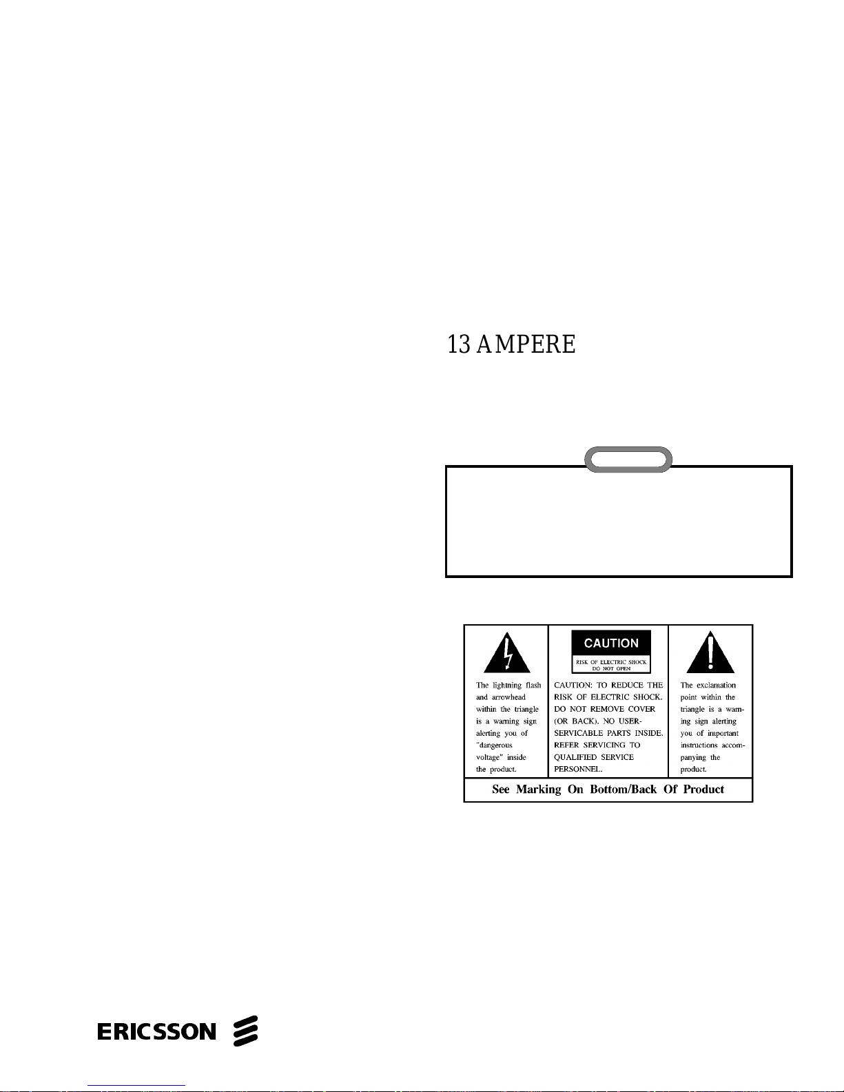
CAUTION
THESE SER VICING INSTRUCTIONS ARE FOR USE BY QU ALIFIED
PERSONNEL ONLY. TO AVOID ELECTRIC SHOCK DO NOT
PERFORM ANY SERVICING OTHER THAN THAT CONTAINED IN
THE OPERATING INSTRUCTIONS UNLESS YOU ARE QU ALIFIED
TO DO SO. REFER ALL SERVICING TO QUALIFIED SERVICE
PERSONNEL.
WARNING: TO PREVENT FIRE OR ELECTRIC SH OCK HAZARD. DO NOT
EXPOSE THIS PRODUCT TO RAIN OR MOISTURE.
CAUTION: TO PREVENT ELECTRIC SHOCK DO NOT USE THIS
(POLARIZED) PLUG WITH AN EXTENSION CORD, RECEPTACLE OR
OTHER OUTLET UNLESS THE BLADES CAN BE FULLY INSERTED TO
PREVENT BLADE EXPOSURE.
ericssonz

LBI-38751
TABLE OF CONTENTS
SPECIFICATIONS . . . . . . . . . . . . . . . . . . . . . . . . . . . . . . . . . . . . . . . . . . . . . . . . . . 3
SAFETY INSTRUC TION S . . . . . . . . . . . . . . . . . . . . . . . . . . . . . . . . . . . . . . . . . . . . . . 4
INTRODUCTION . . . . . . . . . . . . . . . . . . . . . . . . . . . . . . . . . . . . . . . . . . . . . . . . . . . 5
CIRCUIT DESCRIPTION . . . . . . . . . . . . . . . . . . . . . . . . . . . . . . . . . . . . . . . . . . . . . . 5
Input Section . . . . . . . . . . . . . . . . . . . . . . . . . . . . . . . . . . . . . . . . . . . . . . . . . . . 5
Filter And Bridge Section . . . . . . . . . . . . . . . . . . . . . . . . . . . . . . . . . . . . . . . . . . . . 5
Filter And Output Regu lator Se ction . . . . . . . . . . . . . . . . . . . . . . . . . . . . . . . . . . . . . . 5
Overcurrent Protection . . . . . . . . . . . . . . . . . . . . . . . . . . . . . . . . . . . . . . . . . . . . . . 5
Overtemperature Protection . . . . . . . . . . . . . . . . . . . . . . . . . . . . . . . . . . . . . . . . . . . 6
Output Overvoltage Protection . . . . . . . . . . . . . . . . . . . . . . . . . . . . . . . . . . . . . . . . . 6
Internal Bias Voltage Supply . . . . . . . . . . . . . . . . . . . . . . . . . . . . . . . . . . . . . . . . . . . 6
OPERATION . . . . . . . . . . . . . . . . . . . . . . . . . . . . . . . . . . . . . . . . . . . . . . . . . . . . . 6
MAINTENANCE . . . . . . . . . . . . . . . . . . . . . . . . . . . . . . . . . . . . . . . . . . . . . . . . . . . 6
TROUBLESHOOTI NG . . . . . . . . . . . . . . . . . . . . . . . . . . . . . . . . . . . . . . . . . . . . . . . . 6
ADJUSTMENTS . . . . . . . . . . . . . . . . . . . . . . . . . . . . . . . . . . . . . . . . . . . . . . . . . . . 7
INSTALLATION . . . . . . . . . . . . . . . . . . . . . . . . . . . . . . . . . . . . . . . . . . . . . . . . . . . 7
FUSE REPLACEMENT . . . . . . . . . . . . . . . . . . . . . . . . . . . . . . . . . . . . . . . . . . . . . . . 7
TROUBLESHOOTI NG TA BLE . . . . . . . . . . . . . . . . . . . . . . . . . . . . . . . . . . . . . . . . . . . 7
POWER SUPPLY VOLTAGE READING . . . . . . . . . . . . . . . . . . . . . . . . . . . . . . . . . . . . . . 7
APPLICATION . . . . . . . . . . . . . . . . . . . . . . . . . . . . . . . . . . . . . . . . . . . . . . . . . . . . 7
MODIFICATION PROCEDURES . . . . . . . . . . . . . . . . . . . . . . . . . . . . . . . . . . . . . . . . . . 7
ADAPTER CABLE . . . . . . . . . . . . . . . . . . . . . . . . . . . . . . . . . . . . . . . . . . . . . . . . . . 8
PARTS LIST . . . . . . . . . . . . . . . . . . . . . . . . . . . . . . . . . . . . . . . . . . . . . . . . . . . . . . 10
OUTLINE DIAGRAMS . . . . . . . . . . . . . . . . . . . . . . . . . . . . . . . . . . . . . . . . . . . . . . . 11
SCHEMATIC DIAGRAM . . . . . . . . . . . . . . . . . . . . . . . . . . . . . . . . . . . . . . . . . . . . . . 14
Page
Repai rs to this equipm ent shoul d be made only by an author ized se rvice tec hnicia n or facili ty desig nated by t he suppl ier . An y
repairs, alter ations or substituti on of rec ommend ed part s made by the user to this equi pment not ap proved by the m anufac turer
could voi d th e user’s authority to opera te th e equi pm e nt i n ad dit io n to the ma nuf ac turer’ s wa rranty.
This manual is published by Ericsson Inc., without any warranty. Improvements and changes to this manual necessitated by
typographical errors, inaccuracies of current information, or improvements to programs and/or e quipment, may be made by
Ericsson Inc., at any time and without not ice . Such c hanges will be incorporated into new e di ti ons of this manu al . No part of
this manual may be reproduced or transmitted in any form or b y any means, electronic or mec hanical, i ncluding p hotocopying
and recordi ng, for a ny pu rpose , without the expre s s writt en pe rm ission of Ericsson Inc.
Copyright © August 1992, Ericsson GE Mobile Communications Inc.
2
NOTE
SPECIFICATIONS*
A thermal protection unit will automatically reduce the output voltage if the output is at maximum value for an extended period
of time at 13 amperes.
Part No. Nominal
LBI-38751
Input Voltage (Vac) P11,P12
P14
Input Frequency (Hz) ALL 50/60
Input Current (Amps) P11,P12
P14
Output Voltage (Vdc)
(From 0.5 to 13 Amperes)
Output Ripple (mV P-P)
@ 3 Am ps
@ 13 Amps
Tra nsi e n t Respo nse ( Vd c )
(Except overcurrent condition)
Duty Cycle All 20%: 1 minute ON, 4 minutes OFF
Size All 4.6 X 4.75 X 12 . 5 in c hes
Weight All 13 .1 LBS
* These specifications are intended primarily for the use of the service technician. Refer to the appropriate Specification Sheet for
complete specifications.
All 13.8
All
All
All 11.5 - 16.0
121
240
4
2
50 (Ma xi mum)
100 (Maximum)
19A704 647P1- P3 UL Approv al
19A704 647P11-P12 CSA & U L Ap prov a l (Pe ndi ng)
19A704 647P14 Europe an Approva l (Pending )
NOTE
WARNING
This unit contains dangerous voltage levels. It is strongly recommended that defective units be returned to the manufacturer
for repairs.
If field repair is necessary, remove the input power and then use a load resistor to manually discharge each cap acitor before
servicing the unit.
3
LBI-38751
IMPORTANT SAFETY INSTRUCTIONS
1. SAVE THIS MANUAL - It contains important
safety and operating instructions for Power Supply
Models 19A704647 P1, P2, P3 and P11, P12, and
P14.
2. Do not use auxiliary equipment not recommended or
sold by th e ma nufac tur er. To do so may r es ul t in a
risk of fi re, elect ric shock, or injury to personnel.
3. Do not expose unit to rain, snow or other type of
moistu re.
4. To reduce risk of damage to electric plug and cord,
pull by plug rather than cord when d isconnecting
unit.
5. Make sure the cord i s located so t hat it will not be
stepped on, trip ped over, or otherwis e subjec ted to
damag e or stress.
6. An exten sion cord sh ould not be us ed unl ess abs o-
lutely necessary. Use of an improper extension cord
could result in a risk of fire and electric shock. If an
extension cord must be used, make sure:
a. That pins on plug of extension cord are the same
number, size and shapes of those on plug on unit.
b. That extension cord is properly wired, in good
condition, and
c. That wire size is large enough for AC ampere
rating of unit as specified in Tabl e 1.
Table 1 - Recommended Minimum Size For
Extension Cords
10. To reduce ris k of elect ric shock, u nplug unit from
outlet before attem pting any mai nten ance or cleaning.
11. GROUNDING AND AC POWER CORD
CONNECTION - To reduce risk of electrical shock
use only a properly grounded output. The unit is
equipped with an electric cord having an equipment
grounding conductor and a grounding plug. Be sure
that t he o ut let i s pr op erly ins talle d and gr ound ed i n
accordance with all local codes and ordinances.
12. DANGER - Never alter AC cord or plug. If it does
not fit t he out le t, hav e a pro per ou tlet in s tall ed by a
qualified electrician. Improper connection can result
in risk of electric shock.
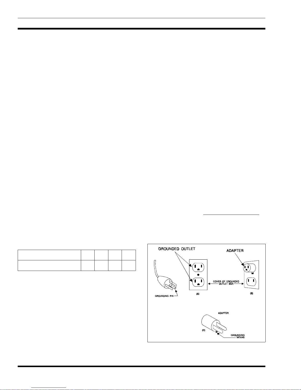
13. This unit is fo r use on a 121 vol t circu it, and ha s a
grounding plug that looks like the plug shown in
Figure 1. A temporary adapter, that looks like t he
adapter shown in sketches B and C, may be u sed to
connect this plug to a two pole receptacle as shown
in sketch B if a properly grounded outlet is not
available. The temporary adapter should be used only
until a pr op erl y gr ou nde d o utl et c an be in stal le d by a
qualified electrician.
14. DANGER - Before using the adapter shown, be
certain that the center screw of the outlet p late is
grounded. The green colored rigid ear or lug extending from the adapter must be connected to a properly
grounded outlet -necessary, replace original ou tlet cover plate screw
with a longer screw that securely fastens the ear or
lug to outlet cover plate and makes a grounded connection to outlet box.
make certain it is grounded. If
Length of Ext e n sio n Cor d( ft .) 25 50 100 150
AWG Size of Exte n sio n C or d 18 18 16 14
7. Do not operate unit with damaged cord or plug replace them immediately.
8. Do not operate unit if it has received a sharp blow,
been dropped, or otherwise damaged in any way.
Return to a qualified service shop.
9. Do not disassemble unit. Return to a qualified service shop when service or repair is required. Incorrect
reassembly may r esult in a r isk of electr ic sh ock o r
fire.
4
Figure 1 - Grounding Methods

LBI-38751
15. The P3 and P14 Power Supplies are for use on circuits
of nominal 240 volts AC. They are factory equipped
with an electric cordless plug connector. A terminating connector that meets local electrical codes should
be added.
16. Care shou ld be taken when pla cing the unit in ser vice
to insure proper top and bottom ventilation. A minimum of 1/4 inch is req uir ed b etw een t he bot tom of
the unit and the surface on which it sits.
INTRODUCTION
These power supplies were designed expressly to provide
power for the D elta Des ktop/Wal l sta t ion. Th ey su pp ly th irteen (13) amperes of direct curren t at 13.8 Volts. The output
is protected from both o ve rcurrent and overvo lt age. In addition, built in overtemperature protection prevents damage
from usage outside of the specified temperature range.
The circuit diagrams of these power supplies (part numbers
P11, P12 an d P14) are the s ame, except for pr imary pow er
connections. The applications are:
Part 1, 11 - For rack Mounting (Delta type) - 120V 60Hz
Part 2 , 12 - Table Mo un tin g ( Rubb e r Fee t) - 120V 6 0H z
Part 3 - Table Mounting (Rubber Feet) - 240V 50Hz
Part 4 - For rack Mounting (Delta type) - 240V 50 Hz
CIRCUIT DESCRIPTION
FILTER AND OUTPUT REGULATOR
SECTION
The c urre nt the n f lows t hr ough th e l ine ar reg ula tor sec ti on
of the supply. The linear regulator is compo sed of two functional groups of components. The first group, the series pass
regulator group consists of Q1, Q2, R1, and R2. In order to
control the o ut pu t vo ltag e of the s uppl y, the serie s pas s tr ansistors are operated as variable resistors. If the lo ad on the
supp ly is in crea sed , cau sing a drop in the ou tp ut vo ltag e, the
resistance of the series pass transistors is automatically decreas ed. This dec reas e bal ances th e out put vo lta ge dro p an d
returns the output voltage back to the desired level.
In order to reg ulate the o utput voltag e, tw o pass tr ansist ors
are used. R1 and R2 provide negative feedback to the emitters
of the resp ectiv e tr ansist ors, balan cing them and cau sing e qual
current flow and equal power dissipation.
The second functional group is the series pass control,
consisting of U1 and Q3 in conjunction wit h their ass oc iated
bias r esistors and decoupling capacitors. U1 continuously
monitors the output voltage developed through the interaction
of the load and the series pass transistors. When more output
voltage is required to maintain regulation, U1 increases drive
to transistor Q3. Q3 provides the amount of series pass transistor base drive necessary to d ecrease their r esistance an d
boost t he ou tput volta ge b ack up to the desir ed val ue. Th is
continuous interaction between the control circuitry and series
pass stage for ms a clos ed loop c ontrol g roup prov iding the
regulated output voltage to the power supply load. The closed
feedb ack loop is co mpen sate d by R4 , C6 , and C 7 to provi de
loop stability. Potentiometer R13 varies the amount of output
voltage fed back in the cont rol loop thus allowing precise
adjustment of the output voltage at which regulation is maintained.
INPUT SECTION
Input power to th e supply i s provided f rom a 121 Vo lt,
50/60 Hertz (or 242 V, 50/60 Hz) line source connected
through the main power cord. The line is passed through fuse
F1, that limits the input current to 4 amperes. The input current
also pass es t hrough v aristor RV1, a transient l imiti ng device
that clamps the line at approximately 160 Vrms. This protects
the device from potentially harmful line voltage excursions.
FILTER AND BRIDGE SECTION
After passing through the input protection devices the line
voltage is applied to the p rimary winding to transformer T1.
The stepped down line voltage of approximat ely 35 Vrms, is
appli ed to the d iode bri dge D 1 and filter capacit ors C1, C2,
and C3. These devices convert the alternating current line to
approximately 25 V o lts direct current.
OVERCURRENT P ROTECTION
Overcurrent protection is implemented via a current foldback scheme. Resistor R3 is used as a current sensing element.
The amou nt of voltage developed across this resi stor is direc tly
proportional to the amount of current flowing to the load. This
sense vo ltage is applied to the regulator control integrated
circuit, U1, by means of R5, R6, and R7. As the current
through the sense resistor increases past 13.8 amps, the sense
voltage seen by U1 causes the value of both output voltage and
output current to dec r eas e. Th is fo ld ba ck a p pr oach to ov ercurrent protection decreases the amount of power dissipated
across the series pass transistors during a faulted condition.
The maximum allowable short circuit current is less than five
(5) amps.
5
 Loading...