

Page 1
Page
1
of
153
Cover
9/11/2012
file://C:\Users\ebriacl\AppData\Local\Temp\~hh7DF.htm
© Ericsson AB 2011. All rights reserved
1553-FGC 101 1010 Uen A
Video Processor
HANDBOOK
VP/CHASSIS/1AC, VP/CHASSIS/2AC and Options
Software Version 1.9.0 (and later)
Preliminary Information
Scope of This Information
This topic defines who should use this information, and what equipment and options are covered.
About This Information
Tabulates the history of this information. Lists the templates and style sheets used to create the file.
Trademarks
List the trademarks and registered trademarks associated with the equipment.
Warning, Cautions and Notes
Defines the use and format of Warnings, Cautions and Notes throughout this information.
Contact Information
Gives contact information for Ericsson Customer Services, and Technical Training.
Compliance Statements
Compliance statements relating to EN55022/AS/NZS 3548 and FCC.
© Ericsson AB 2011. All rights reserved
Page 2
Scope of This Information
Page
2
of
153
Cover
9/11/2012
file://C:\Users\ebriacl\AppData\Local\Temp\~hh7DF.htm
Who Should Use this Handbook
This guide is written for operators and users of the Video Processor and describes its functions and operation. It will assist in the
installation and day-to-day care and operation of the unit. Maintenance information that requires covers to be removed is not
included.
Do not remove the covers of this equipment. Hazardous voltages are present within this equipment and may be exposed if the
covers are removed. Only suitably trained and experienced service engineers are permitted to service this equipment.
Unauthorised maintenance or the use of non-approved replacements may affect the equipment specification and invalidate any
warranties.
WARNING!
CAUTION!
What Equipment is Covered by this Handbook
The Equipment Models
Front View of the Video Processor.
Rear View of the Video Processor, single AC PSU variant.
Rear View of the Video Processor, dual AC PSU variant
Product Codes
This information covers products with the marketing codes shown in the following table
Marketing Code Description Summary of Features
VP/CHASSIS/1AC Video Processor with single AC input See Introduction>Base Chassis>Base Unit (AC)
VP/CHASSIS/2AC Video Processor with single AC input See Introduction>Base Chassis>Base Unit (Dual AC)
VP/HWO/EN8190/ENC EN8190 H.264 HD Encoder Module See Introduction>Option Cards>EN8190 HD H.264 VCM
VP/HWO/EN8100/ENC EN8100 MPEG-2 SD Encoder Module See Introduction>Option Cards>EN8100 SD MPEG-2 VCM
VP/HWO/EN7100/ENC EN7100 MPEG-2 SD Encoder Module See Introduction>Option Cards>EN7100 SD MPEG-2 VCM
VP/HWO/EN8130/ENC EN8130 H.264 SD Encoder Module See Introduction>Option Cards>EN8130 SD H.264 VCM
Page 3

VP/HWO/EN8180/ENC EN8180 MPEG-2 HD Encoder Module See Introduction>Option Cards>EN8180 HD MPEG-2 VCM
FGC 101
Page
3
of
153
Cover
9/11/2012
file://C:\Users\ebriacl\AppData\Local\Temp\~hh7DF.htm
VP/HWO/ASI/2IN2OUT ASI I/O Module See Introduction>Option Cards>ASI Option Module
VP/HWO/EXTSYNC Video Processor External Sync Module See Introduction>Option Cards>External Sync Input
VP/CAB/BAL
VP/CAB/UNBAL
Firmware/Software Versions
This information covers the functionality of the firmware/software versions which are contained within the Software Release Version
1.9.x .
This handbook continues to be relevant to subsequent build versions where the functionality of the equipment has not changed.
Where the build standard changes the functionality, a new issue of this handbook will be provided.
© Ericsson AB 2011. All rights reserved
D-Type to balanced XLR breakout
cable
D-Type to unbalanced XLR breakout
cable
See Installing the Equipment>External Interfaces> VCM>Audio
Input
See Installing the Equipment>External Interfaces> VCM>Audio
Input
About this Information
Revisions
Any revision of this information will be by a complete reissue.
Issues are listed below:
Issue Date Build Version Comments
1 July 2009 1.0 Initial release.
2 October 2009 1.1
3 January 2010 1.2
4 December 2010 1.6
5 January 2011 1.9
© Ericsson AB 2011. All rights reserved
New release with
additional features
New release with
additional features
New release with
additional features
New release with
additional features
Ericsson Document
Number 1553-
1010 Uen A
Trademarks
General
All best endeavours have been made to acknowledge registered trademarks and trademarks. Any notified omissions will be rectified
in the next issue. Some trademarks may be registered in some countries but not in others.
Registered trademarks and trademarks used are acknowledged below and marked with their respective symbols. However, they are
not marked further within the text.
Copyright
© Ericsson AB 2010. All rights reserved. No part of this document may be reproduced in any form without the written permission of
the copyright owner.
Page 4

Disclaimer
Cautions give information which, if strictly followed, will prevent damage to equipment or other goods. They are boxed for emphasis,
Page
4
of
153
Cover
9/11/2012
file://C:\Users\ebriacl\AppData\Local\Temp\~hh7DF.htm
The contents of this document are subject to revision without notice due to continued progress in methodology, design and
manufacturing. Ericsson AB shall have no liability for any error or damage of any kind resulting from the use of this document.
Registered Trademarks
Dolby® is a registered trademark of Dolby Laboratories Licensing Corporation.
DTS® is a registered trademark of Digital Theater Systems, Inc
Ethernet® is a registered trademark of Xerox Corporation.
Trademarks
Ethafoam™ is a trademark of The Dow Chemical Company.
Pozidriv™ is a trademark of European Industrial Services.
Reflex™ is a trademark of Ericsson Television.
Stratocell™ is a trademark of the Sealed Air Corporation.
© Ericsson AB 2011. All rights reserved
Warnings, Cautions and Notes
Heed Warnings
All warnings on the product and in the operating instructions should be adhered to. The manufacturer can not be held responsible
for injuries or damage where warnings and cautions have been ignored or taken lightly.
Read Instructions
All the safety and operating instructions should be read before this product is operated.
Follow Instructions
All operating and use instructions should be followed.
Retain Instructions
The safety and operating instructions should be retained for future reference.
Warnings give information which, if strictly observed, will prevent personal injury or death, or damage to personal property or the
environment. They are boxed for emphasis, as in this example, and are placed immediately preceding the point at which the reader
requires them.
as in this example, and are placed immediately preceding the point at which the reader requires them.
NOTE: Notes provide supplementary information. They are highlighted for emphasis, as in this example, and are placed
© Ericsson AB 2011. All rights reserved
immediately after the relevant text.
WARNING!
CAUTION!
Page 5

Contact Information
Page
5
of
153
Cover
9/11/2012
file://C:\Users\ebriacl\AppData\Local\Temp\~hh7DF.htm
Ericsson Customer Services
Support Services
Our primary objective is to provide first class customer care that is tailored to your specific business and operational requirements.
All levels are supported by one or more service performance reviews to ensure the perfect partnership between Ericsson and your
business.
Warranty
All Ericsson Products and Systems are designed and built to the highest standards and are covered under a comprehensive 12
month warranty.
Levels of Continuing Ericsson Service Support
For stand-alone equipment, then Ericsson's BASIC Essential support is the value for money choice for you.
BASIC provides you with year-by-year Service long after the warranty has expired.
For systems support you can choose either Gold Business Critical support or Silver Business Advantage. These packages are
designed to save you costs and protect your income through enlisting the help of our support specialists.
Call Ericsson Sales for more details.
Where to Find Us
Customer Services
Europe, Middle East
and Africa
Fax: +44 (0) 23 8048 4467
Email: tvsupportemea@ericsson.com
Americas Tel: +888 671 1268 US and Canada
Tel: +678 812 6255 International
Fax: +678 812 6262
Email: tvsupportamericas@ericsson.com Compression
Email: tvsupport@ericsson.com Software Support Centre
China Tel: +86 10 8476 8676 Beijing
Fax: +86 10 8476 7741 Beijing
Tel: +852 2590 2388 Hong Kong
Fax: +852 2590 9550 Hong Kong
Email: tvsupportapac@ericsson.com
Australia and New
Zealand
Fax: +612 (0) 9111 4949
Email: tvsupportanz@ericsson.com
Internet Address www.ericsson.com
Tel: +44 (0) 23 8048 4455
Tel: +612 (0) 9111 4027
Page 6

Technical Training
technologies. We can provide both regularly scheduled courses and training tailored to individual needs. Courses can be run either at
Page
6
of
153
Cover
9/11/2012
file://C:\Users\ebriacl\AppData\Local\Temp\~hh7DF.htm
Training Courses
Ericsson provides a wide range of training courses on the operation and maintenance of our products and on their supporting
your premises or at one of our dedicated training facilities.
Where to Find Us
For further information on the Ericsson training programme please contact us:
International Tel: +44 (0) 23 8048 4229
Fax: +44 (0) 23 8048 4161
Email: tvglobaltraining@ericsson.com
Return of Equipment
Contact your regional Ericsson office who will issue directions on how and where to return a unit for service/repair/upgrade.
© Ericsson AB 2011. All rights reserved
EN55022 and CISPR22
This is a Class A product. In a domestic environment this product may cause radio interference in which case the user may be
required to take adequate measures.
FCC
This equipment has been tested and found to comply with the limits for a Class A digital device, pursuant to Part 15 of the FCC
Rules. These limits are designed to provide reasonable protection against harmful interference when the equipment is operated in a
commercial environment.
This equipment generates, uses and can radiate radio frequency energy and, if not installed and used in accordance with the
Handbook, may cause harmful interference to radio communications. Operation of this equipment in a residential area is likely to
cause harmful interference in which case the user will be required to correct the interference at ones own expense.
FCC Code of Federal Regulations (CFR) Title 47 – Telecommunications, Part 15: radio frequency devices, subpart B – Unintentional
Radiators.
© Ericsson AB 2011. All rights reserved
Read This First!
Personnel
Ensure the personnel designated to fit the unit have the appropriate skills and knowledge. If in any doubt, contact Customer
Services (see Contact Information).
Installation
Installation of the product should follow these instructions, and should only use installation accessories recommended by the
manufacturers. When rack mounted, this equipment must have shelf supports as well as being fixed at the front panel.
Page 7

Mechanical Support
Page
7
of
153
Cover
9/11/2012
file://C:\Users\ebriacl\AppData\Local\Temp\~hh7DF.htm
Do not use this product as a support for any other equipment.
Web Browser access
This product is designed to support control through Web browser access. The only supported browser is Microsoft IE8 (earlier
versions of IE are not supported)
© Ericsson AB 2011. All rights reserved
Introduction
The Unit is a flexible platform consisting of a base unit or chassis in to which various option cards can be plugged. The base unit
provides an Ethernet control interface, and Ethernet data interfaces, it also provides basic transport stream processing functionality.
Other functionality such as video encoding, audio encoding, or other input or output interfaces are provided by option cards.
License Keys
License Keys control the availability of some of the features accessible from the unit and are issued to a specific chassis, not an
option card, and are held within the chassis.
Base Chassis
This section introduces the chassis and describes the functions associated with the host controller.
Option Cards
The following are the available option cards:
EN7100 SD MPEG-2 VCM
This provides high quality MPEG-2 Video encoding, and audio encoding.
EN8100 SD MPEG-2 VCM
This provides ultimate quality MPEG-2 Video encoding, and audio encoding.
EN8130 SD H.264 VCM
This provides high quality H.264 Video encoding, and audio encoding.
EN8180 HD MPEG-2 VCM
This provides high quality MPEG-2 Video encoding, and audio encoding.
EN8190 HD H.264 VCM
This provides ultimate quality H.264 Video encoding, and audio encoding.
ASI I/O Module
This provides two ASI outputs of the same transport stream. (ASI input functionality will be added in a subsequent release).
External Sync Input
This allows a studio reference to be input in to the unit to which a 27 MHz system clock reference may be locked.
© Ericsson AB 2011. All rights reserved
License Keys
Overview
Page 8

License Keys control the availability of some features and are issued to a specific base unit not an option card, even if the
. This page displays the marketing code, number of each license and a description of the
Page
8
of
153
Cover
9/11/2012
file://C:\Users\ebriacl\AppData\Local\Temp\~hh7DF.htm
functionality being enabled is provided by an option card.
Features
License Keys consist of a feature, and the number of instances of this feature that are allowed within the chassis.
License Keys are allocated on a ‘first configured first served’ basis within the chassis. If an attempt is made to enable a feature, but
the required license key is not available then the feature is not enabled, and a log message is generated.
When a function that has a license associated with it is disabled, the license key is released within 1 second, and therefore available
to be re-allocated .
Verifying which licenses are present in the Unit
Access to the encoder web pages is necessary to verify the licenses that are enabled on the unit.
Navigate to Configure > System > Licenses
feature enabled by the license.
NOTE : Short term licenses are not supported.
Ordering Additional Licenses.
When ordering additional licenses for existing units the following information is needed:
1. Unique Chip ID of the unit is required to generate the key.
This is retrieved by navigating to the following web page :
Configure > System > Base Unit > Advanced > ChipID
2. The TOTAL FINAL number of licenses required (including licenses already enabled on the unit) needs to be provided.
The above information is used to generate a new license key file, which then needs to be loaded onto the appropriate unit.
Entering License Keys
The keys are saved in an XML (newlicensedetail.xml) ready to be entered onto the unit via the web page
Browse to: Configure > Licenses
In the license box enter the license filename and select upload.
NOTE : The front panel CANNOT be used to enter license keys!
© Ericsson AB 2011. All rights reserved
Base Chassis
Overview
The base chassis provides the control interfaces, the data Ethernet ports, data routing between the Ethernet ports, control software
running on the base chassis, and the option cards. It also provides the ability to generate MPEG-2 transport streams from
elementary streams received from the option cards.
The following is a summary of the features of the base chassis:
19” 1 ‘RU’ rack mount chassis.
Front panel LCD and keypad for limited control and status reporting.
Tri-colour LED to indicate chassis health.
Dual redundant Ethernet control ports.
Two pairs of dual redundant Ethernet ports for data input and output.
Single or dual AC power supply variants.
6 option card slots (single AC PSU chassis) or 4 option card slots (dual AC PSU chassis)
Option cards are ‘hot swappable’.
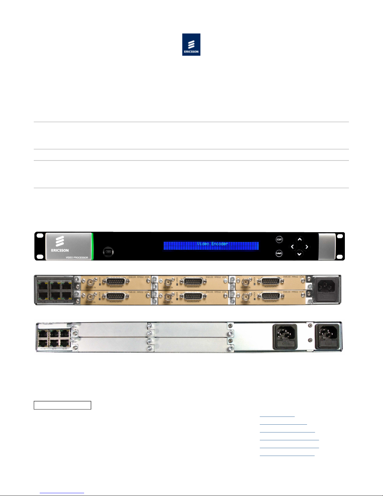
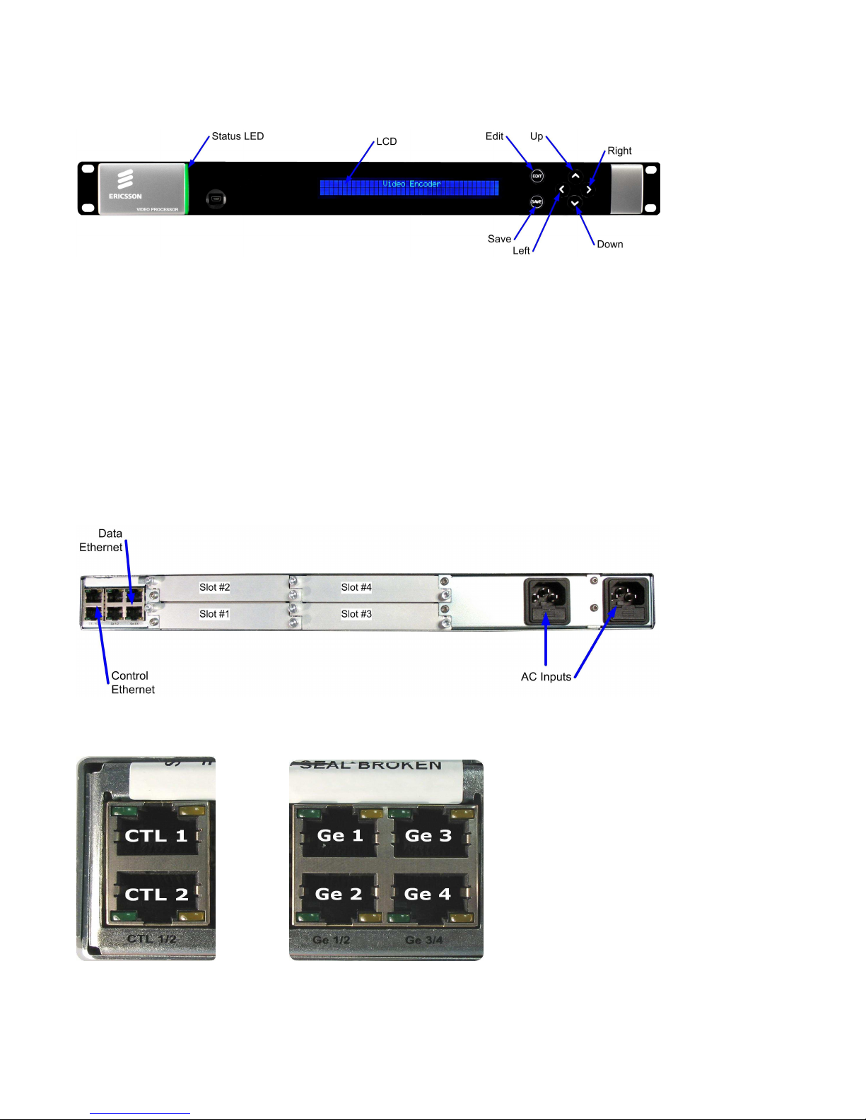
Video Processor Front Panel
Page 9
Page
9
of
153
Cover
9/11/2012
file://C:\Users\ebriacl\AppData\Local\Temp\~hh7DF.htm
Video Processor Rear Panel - Single AC Chassis (EN8100 SD MPEG-2 VCMs fitted)
Video Processor Rear Panel - Dual AC Chassis
NOTE: Refer to Installing the Equipment > External Interfaces > Base Chassis for more details of the items at the rear and
front panels.
VP/CHASSIS/1AC 1U Base Chassis (AC)
Describes the single AC power supply base chassis.
VP/CHASSIS/2AC 1U Base Chassis (Dual AC)
Describes the dual AC power supply base chassis.
© Ericsson AB 2011. All rights reserved
VP/CHASSIS/1AC 1U Base Chassis (AC)
Overview
The Video Processor consists of a base chassis, a single AC mains input and up to six option cards. The base chassis is a 1 ‘RU’ 19”
rack mount chassis that provides the control interfaces, and two pairs of dual redundant Ethernet ports for data input and output.
The option cards provide the video, audio and data processing functionality and can be ‘Hot Swapped’, i.e. inserted or removed
whilst the chassis is powered.
Single AC PSU Base Chassis
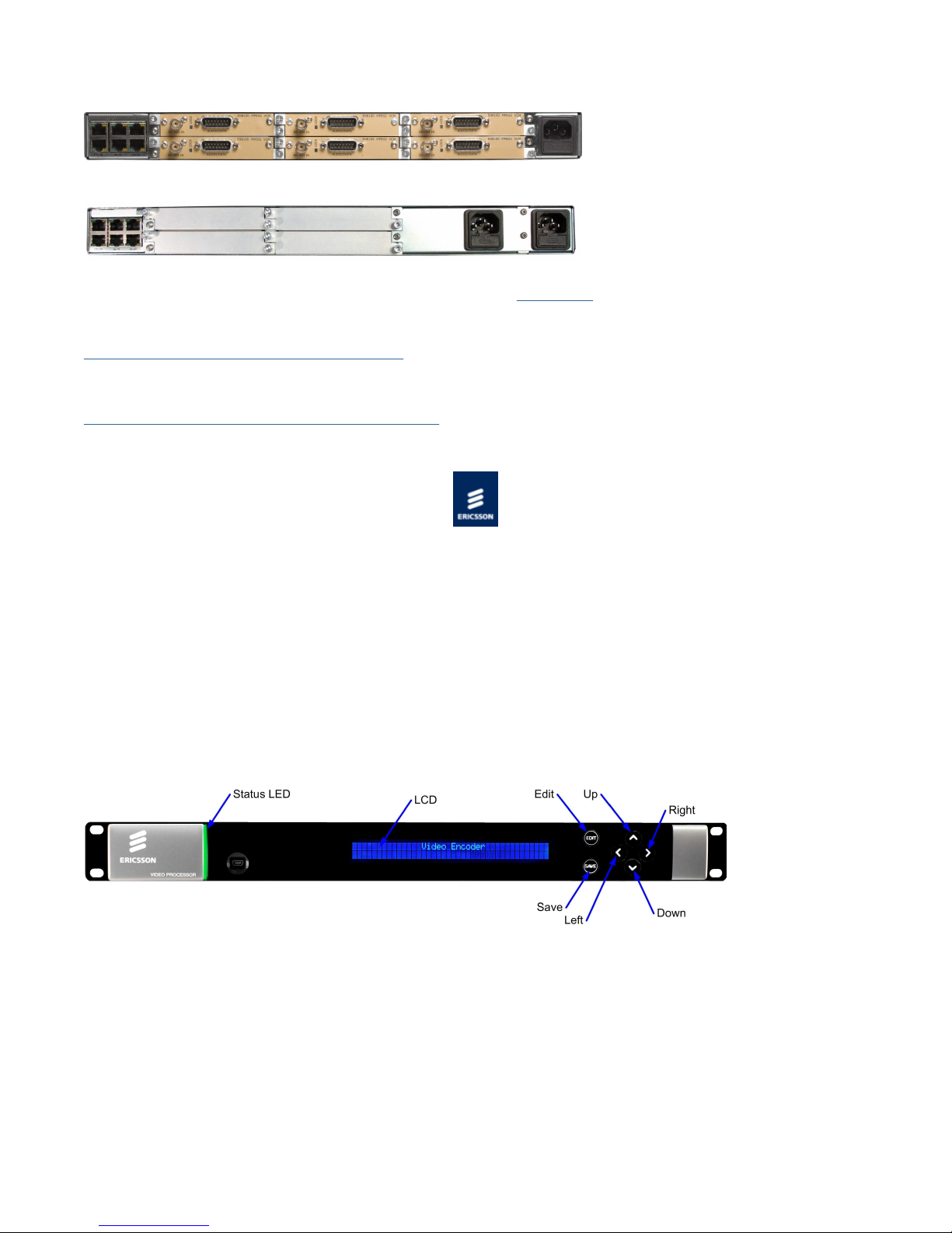
Front Panel
VP/CHASSIS/1AC Front Panel Items
LCD
Control and status information is displayed on a 2 line by 40 character display.
Buttons
Six buttons are provided for navigating through the front panel menus.
Status LED
The status LED is green when there are no active alarms or warnings and red if there is a critical alarm.
The status LED is amber if there is an active warning, minor or major alarm.
USB Connector
This is not for customer use.
Page 10
Page
10
of
153
Cover
9/11/2012
file://C:\Users\ebriacl\AppData\Local\Temp\~hh7DF.htm
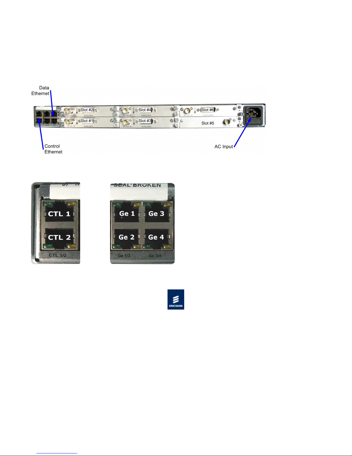
Rear Panel
The option cards, control Ethernet ports, data Ethernet ports, and the AC power input are all accessible at the rear of the base
chassis.
VP/CHASSIS/1AC Rear Panel Items [Single AC Chassis]
Ethernet Port Numbering
© Ericsson AB 2011. All rights reserved
VP/CHASSIS/2AC 1U Base Chassis (Dual AC)
Overview
The Video Processor consists of a base chassis, dual AC inputs and up to four option cards. The base chassis is a 1 ‘RU’ 19” rack
mount chassis that provides the control interfaces, and two pairs of dual redundant Ethernet ports for data input and output.
The option cards provide the video, audio and data processing functionality and can be ‘Hot Swapped’, i.e. inserted or removed
whilst the chassis is powered.
Why Have Two Mains Connectors
Many broadcasting sites have two power supply chains, either from the master switchboard or, for major sites, from different points
on the supply grid. As the most common cause of system failure is loss of power, feeding the chassis from the separate chains
ensures reliability of supply and, therefore, continuity of service.
Dual AC PSU Base Chassis
Page 11
Front Panel
Page
11
of
153
Cover
9/11/2012
file://C:\Users\ebriacl\AppData\Local\Temp\~hh7DF.htm
VP/CHASSIS/2AC Front Panel Items
LCD
Control and status information is displayed on a 2 line by 40 character display.
Buttons
Six buttons are provided for navigating through the front panel menus.
Status LED
The status LED is green when there are no active alarms or warnings and red if there is a critical alarm.
The status LED is amber if there is an active warning, minor or major alarm.
USB Connector
This is not for customer use.
Rear Panel
The option cards, control Ethernet ports, data Ethernet ports, and the AC power input are all accessible at the rear of the base
chassis.
VP/CHASSIS/2AC Rear Panel Items [Dual AC Chassis]
Ethernet Port Numbering
© Ericsson AB 2011. All rights reserved
Page 12

Option Cards
This card can compress a standard definition video input using H.264 encoding, and can compress up to eight channel pairs of audio
Page
12
of
153
Cover
9/11/2012
file://C:\Users\ebriacl\AppData\Local\Temp\~hh7DF.htm
Option Card Combinations
Describes the supported combinations of option cards, maximum number of cards and recommended slot location for each option
card.
The following are the option cards supported in this release:
EN7100 SD MPEG-2 VCM (VP/HWO/EN7100/ENC)
This card can compress a standard definition video input using MPEG-2 encoding, and can compress up to eight channel pairs of
audio depending on audio encoding mode.
EN8100 SD MPEG-2 VCM (VP/HWO/EN8100/ENC)
This card can compress a standard definition video input using MPEG-2 encoding, and can compress up to eight channel pairs of
audio depending on audio encoding mode.
EN8130 SD H.264 VCM (VP/HWO/EN8130/ENC)
depending on audio encoding mode.
EN8180 HD MPEG-2 VCM (VP/HWO/EN8180/ENC)
This card can compress a high definition video input using MPEG-2 encoding, and can compress up to eight channel pairs of audio
depending on audio encoding mode.
EN8190 HD H.264 VCM (VP/HWO/EN8190/ENC)
This card can compress a high definition video input using H.264 encoding, and can compress up to eight channel pairs of audio
depending on audio encoding mode.
ASI Option Module(VP/HWO/ASI/2IN2OUT)
This card provides a dual ASI output.
External Sync Input (VP/HWO/EXTSYNC)
This card provides an external synchronization input
© Ericsson AB 2011. All rights reserved
Option Card Combinations
The following table lists the number of VCM option cards that can be fitted to a chassis and which slots are recommended for each.
Option
Module
Maximum Number of
Modules
Single PSU Dual PSU
Recommended Slot
Single or Dual PSU
2 pair 2 pair
EN8190
Fitted as a pair only in slots 3 & 4 or slots 1 & 2
(slot 1 or 3 = pre-processor, slot 4 or 5 = encoder)
Page 13

HD H.264 VCM Note: If 2 x EN8190 fitted then the only other modules
that may be fitted are the ASI IO module or the External
Page
13
of
153
Cover
9/11/2012
file://C:\Users\ebriacl\AppData\Local\Temp\~hh7DF.htm
Sync module.
EN8100
SD MPEG-2 VCM
EN7100
SD MPEG-2 VCM
EN8130
SD H.264 VCM
EN8180
HD MPEG-2
VCM
ASI IO Module 6 4 Slot 1 or slot 6
External SYNC
Module
6 4 Any slot
6 4 Any slot
6 4 Any slot
6 4 Any slot
1 1 Any slot
Slot Numbering
Single PSU Chassis
Dual PSU Chassis
© Ericsson AB 2011. All rights reserved
SLOT 2 SLOT 4 SLOT 6
SLOT 1 SLOT 3 SLOT 5
SLOT 2 SLOT 4
SLOT 1 SLOT 3
EN7100 SD MPEG-2 VCM Module
The EN7100 SD MPEG-2 VCM (HWO/EN7100/ENC) allows a high level of MPEG-2 encoding performance.
Summary of Features
Summarises the major functionality associated with the EN7100 SD MPEG-2 VCM.
SD MPEG-2 Video Encoding
Describes the Video processing functionality available in the EN7100 SD MPEG-2 VCM.
Audio Encoding
Describes the Audio Inputs and Coding Modes provided by the EN7100 SD MPEG-2 VCM.
Vertical Blanking Interval Coding
Describes the VBI data extraction and processing capabilities of the EN7100 SD MPEG-2 VCM.
© Ericsson AB 2011. All rights reserved
Page 14
Summary of Features
Page
14
of
153
Cover
9/11/2012
file://C:\Users\ebriacl\AppData\Local\Temp\~hh7DF.htm
Overview
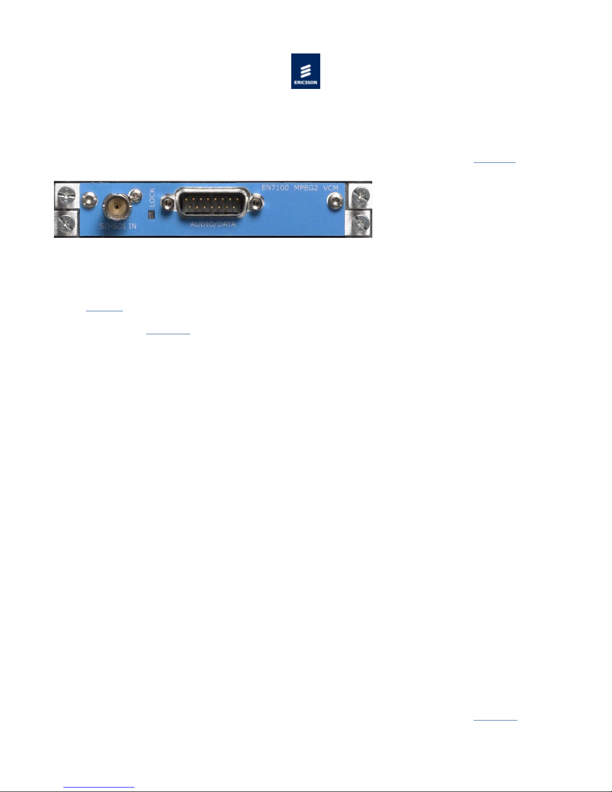
The EN7100 SD MPEG-2 Video Compression Module (VCM) option card can encode a single standard definition video input using the
MPEG-2 algorithm.
EN7100 SD MPEG-2 VCM Rear Panel
Inputs
The card provides an SDI video input via a BNC connector, and digital audio input via a 15-way D-type connector.
SDI Input via a 75 Ω BNC female connector.
Audio Input via a 15-way D-Type male connector for audio and (see Installing the Equipment> External Interfaces > SD
MPEG-2 VCM > Audio Input)
Video
SDI video input.
Frame re-synchronization.
Programmable bandwidth filter.
Adaptive spatial and temporal noise reduction (software option VP/SWO/SDMP2/NR)
MPEG-2 MP@ML Video Encoding (0.256 to 15 Mbps)
Vertical resolution: 576 or 288 (PAL), 480 or 240 (NTSC)
Horizontal Resolution: 720, 704, 640, 544, 528, 480, 352.
Auto Field/Frame picture encoding.
Auto Concatenation (software option VP/SWO/ACON), Scene Cut Detection, Adaptive GOP Structure and Length.
VBI Data
World Standard Text (WST – ETS300472) (625 line only)
Closed Captions: EIA-608, EIA-708 via SMPTE 334, or line 21.
SMPTE 2016-3 AFD and Bar Data
Wide Screen Signaling (WSS or WSS-AFD)
Monochrome samples
Audio Compression
Eight channels AES/EBU digital audio input either de-embedded from SDI or via AES/EBU input connector.
Supported audio coding modes:
- MPEG-1 Layer II (32 kbps to 384 kbps)
- Dolby Digital (56 kbps to 640 kbps) (software option VP/SWO/AC3)
- Pass through of pre-encoded Dolby Digital or Dolby Digital Plus
- AAC
- Transcode from Dolby E
Indications
LED indication for SD SDI lock status (see Installing the Equipment> External Interfaces > SD MPEG-2 VCM > Video Input: LED
Indication).
Page 15

2 main Profile @ Main Level
2 VCM can be configured to select Black, Bars and Red (a test pattern) or a freeze frame as the
Page
15
of
153
Cover
9/11/2012
file://C:\Users\ebriacl\AppData\Local\Temp\~hh7DF.htm
© Ericsson AB 2011. All rights reserved
SD MPEG-2 Video Encoding
Inputs
SDI Input via 75 ohm BNC connector.
Digital Audio Input via 15 way D-Type connector
Overview
The SD MPEG-2 VCM can encode one standard definition video input. It can also encode up to eight channel pairs of audio (with
appropriate licences), or pass through pre-encoded Dolby Digital encoded audio.
The video input signal is processed in to a compressed encoded bit-stream in accordance with the MPEG(MP@ML) specification (ISO/IEC 13818).
A constant bit rate (CBR) output can be produced and may be set to between 256 kbps and 15 Mbps. The card can also produce a
variable bit rate output when operating as part of a Reflex statistical multiplexing system.
The video signal can be subjected to spatial filtering and motion adaptive noise reduction prior to being MPEG-2 encoded.
Video Compression Functionality
The following is a summary of the Video Compression functionality available from the EN8100 SD MPEG-2 VCM.
Function Comments
MPEG-2 Main Profile @ Main Level encoding See Transport Stream Output Overview for transport stream rates.
Variable Seamless Mode
Support for a constant bit rate mode
Support for current reflex mode (look ahead
mode 4)
Video Input 720x576, 25 Hz
Video Input 720x480, 29.97 Hz
Output resolutions 720, 704, 640, 544, 528,
480, 352 X 576/480 352 X 288/240
Support for different resolutions including the standard set of video
picture resolutions for both 625 (576/288 PAL) and 525 (480/240
NTSC) line operation.
Test Patterns
The video pre-processor has the facility to generate a test pattern.
Loss of Video Input
On loss of video input, the SD MPEGoutput. It is also possible to configure it to stop generating the compressed video component on loss of the video input.
Impairment Reduction
The video pre-processor provides spatial/temporal noise reduction which is motion adaptive (with appropriate licences).
Impairment Reduction Comments
Spatial Filtering
Noise Reduction (motion adaptive)
Only available if license VP/SWO/SDMP2/NR has
been purchased.
Page 16
See also Technical Specification > SD MPEG-2 VCM > Video > Impairment Reduction.
Page
16
of
153
Cover
9/11/2012
file://C:\Users\ebriacl\AppData\Local\Temp\~hh7DF.htm
© Ericsson AB 2011. All rights reserved
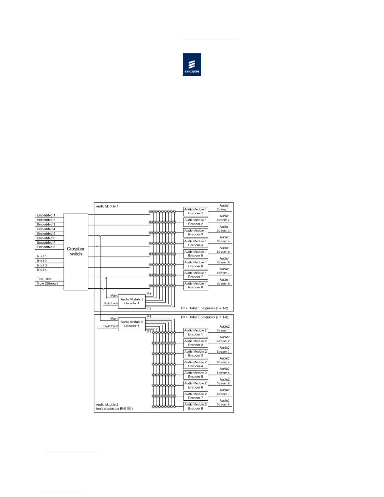
Audio Encoding
Overview
Up to eight channel pairs can be de-embedded from the HD-SDI or SDI video input, or up to four channel pairs can come via the 15
way D-Type Audio Input connector on the cards rear panel as either balanced or unbalanced AES/EBU digital audio.
If a /SWO/DOLBY/AC3 license key is available, two audio channel pairs may be encoded in accordance with the Dolby Digital
specification.
Up to eight audio channel pairs of uncompressed audio can be encoded in accordance with MPEG-1 Layer II, subject to license
key /SWO/M1L2 for more than two channels.
Audio that has already been Dolby Digital encoded can be input, and suitably encapsulated for inclusion in an output transport
stream (pass through mode).
A total number of eight audio channel pairs can be processed of which up to two channel pairs can be encoded in accordance with
the Dolby Digital specification
Audio Input
The Pre-processing function on the VCM accepts digital audio input from either de-embedding from the HD/SD-SDI input, as a
balanced pair (110 Ω) or unbalanced input (75 Ω) from the D type back panel connector.
See Technical Specification for more details.
Page 17

HD-SDI Input
Page
17
of
153
Cover
9/11/2012
file://C:\Users\ebriacl\AppData\Local\Temp\~hh7DF.htm
Audio can be embedded on a serial digital interface (HD-SDI) feed within four groups. Each group contains two pairs. Hence each
HD-SDI can carry up to a maximum of 2 x 4 = 8 pairs, or 16 mono channels.
Each group has an associated Data Identifier (DID). The DIDs are set to the SMPTE 299M defaults for audio group 1 to group 4:
Group 1 = 0x2E7
Group 2 = 0x1E6
Group 3 = 0x1E5
Group 4 = 0x2E4
The DIDs are located in ancillary packets in the data stream. They are fixed at the SMPTE 299M defaults.
SD-SDI Input
Audio can be embedded on a serial digital interface (SDI) feed within four groups. Each group contains two pairs. Hence each SDI
can carry up to a maximum of 2 x 4 = 8 pairs, or 16 mono channels.
Each group has an associated Data Identifier (DID). The DIDs are set to the SMPTE 272M defaults for audio group 1 to group 4:
Group 1 = 0x2FF
Group 2 = 0x1FD
Group 3 = 0x1FB
Group 4 = 0x2F9
The DIDs are located in ancillary packets in the data stream. They are fixed at the SMPTE 272M defaults. DID 1F4 is reserved for
EDH error packets. Refer to the SMPTE 272M specification for more details.
Audio Input
The digital input of the VCM accepts four stereo pairs of digital audio.
See Technical Specification for more details.
CAUTION...
When the digital audio source is used with the AUDIO IN connector, consideration must be given to the choice of clock source used
by the Encoder. To ensure correct operation, both the Encoder and the audio source may need to be genlocked to the studio source
by selecting the video clock as external. Then the encoding clock is derived from an External Sync module.
Audio Encoding Modes
Up to eight audio channel pairs of uncompressed audio can be encoded in accordance with MPEG-1 Layer II, subject to license key
SWO/M1L2 for more than two channel pairs.
If a SWO/AC3 license key is available, two audio channel pairs may be encoded in accordance with the Dolby Digital specification.
Pre-encoded Dolby Digital, Dolby Digital Plus and Dolby E inputs can be suitably encapsulated for inclusion in an output transport
stream.
The VCM can generate a 1 kHz test tone, which may be used in place of any audio input.
Any audio input can be associated with the video being processed, and the audio encoding delay will be matched to the video
encoding delay so that audio/video synchronisation (lipsync) is maintained.
All Audio modes are configurable on a per channel basis, which includes the source of the audio, its encoding configuration and
output PID.
The following is a summary of the Audio Compression functionality available.
Function Comments Maximum number of instances
MPEG-1 Layer II audio
Dolby Digital encoding
The encode of two channel pairs is provided as
standard. More than two encodes require
the /SWO/M1L2 license (one license for each
additional channel pair)
Only available if /SWO/DOLBY/AC3 license has
8 (mono or stereo)
2 (mono or stereo)
Page 18

been purchased
Page
18
of
153
Cover
9/11/2012
file://C:\Users\ebriacl\AppData\Local\Temp\~hh7DF.htm
Dolby Digital pass through (Dolby
Digital AC-3)
Dolby Digital Plus pass through Glitch suppression is supported in this mode 8
DolbyE pass through Compliant with SMPTE 302M 8
LPCM pass through Compliant with SMPTE 302M 8
Glitch suppression is supported in this mode 8
Glitch Suppression Mode
When in Dolby Digital pass through mode, the coding module monitors the encoded bitstream and if the framing structure is
incorrect, a valid silence frame or the last good frame is inserted in its place. If this state occurs for more than a second, the
Encoder signals that the Dolby Digital bitstream is corrupted.
Test Tone
The VCMs can generate a test tone on any audio channel at 1 kHz
Advanced Settings
Dolby Digital (AC-3) components by default use the descriptor defined by the DVB in the PMT. However the AC-3 PMT Descriptor
Syntax control available in the Audio Module/Advanced menu enables this descriptor to be forced to the ATSC AC-3 descriptor.
© Ericsson AB 2011. All rights reserved
Vertical Blanking Interval (VBI) Data
General
All VBI information carriage are configurable (either enabled or disabled). The video line from which the VBI is extracted is
configurable. The default is set according to the recognised standard for the VBI type.
VBI Lines
Up to at least 8 VBI lines per field can be extracted. Unless otherwise stated, all VBI data are formed into one VBI transport stream
packet that conforms to ETSI EN 301 775 or SCTE 127.
VBI Data
Data can be extracted from the vertical blanking interval of the incoming video stream, processed, and then included in the output
transport stream.
The following is a summary of the VBI Data functionality available from the unit.
Component Comments
Video Index It is possible to extract video index and another VBI type from the same line.
Closed Captions
Monochrome 4:2:2 Up to 3 lines can be extracted per frame.
Teletext Up to 18 lines can be extracted per field.
Aspect Ratio Signalling WSS/WSS-AFD/AFD/AFD and Bar Data via VANC
Via line 21 & 284 (CEA-608C) or SMPTE 334 (extracted from VANC data - 525
Line only).
VBI Data on a Separate PID
The VBI data is packetised within MPEG-2 PES packets as specified in ETSI ETS 300-472 (teletext), ETSI EN 301 775 or SCTE 127
for all other VBI data.
Refer to Transport Stream Output > VBI Data on a Separate PID for more information.
Closed caption data, and aspect ratio signalling can also be inserted in to the compressed video elementary stream.
Page 19
Timing
The VCM aligns VBI data and compressed video frames within the bounds dictated by time stamping of received data, i.e. stamp the
Page
19
of
153
Cover
9/11/2012
file://C:\Users\ebriacl\AppData\Local\Temp\~hh7DF.htm
same PTS on the video and VBI that came in on the same frame.
© Ericsson AB 2011. All rights reserved
EN8100 SD MPEG-2 VCM Module
The EN8100 SD MPEG-2 VCM (HWO/EN8100/ENC) has a unique processing engine that extracts the maximum efficiency possible
from the MPEG-2 specification.
Summary of Features
Summarises the major functionality associated with the EN8100 SD MPEG-2 VCM.
SD MPEG-2 Video Encoding
Describes the Video processing functionality available in the EN8100 SD MPEG-2 VCM.
Audio Encoding
Describes the Audio Inputs and Coding Modes provided by the EN8100 SD MPEG-2 VCM.
Vertical Blanking Interval Coding
Describes the VBI data extraction and processing capabilities of the EN8100 SD MPEG-2 VCM.
© Ericsson AB 2011. All rights reserved
Summary of Features
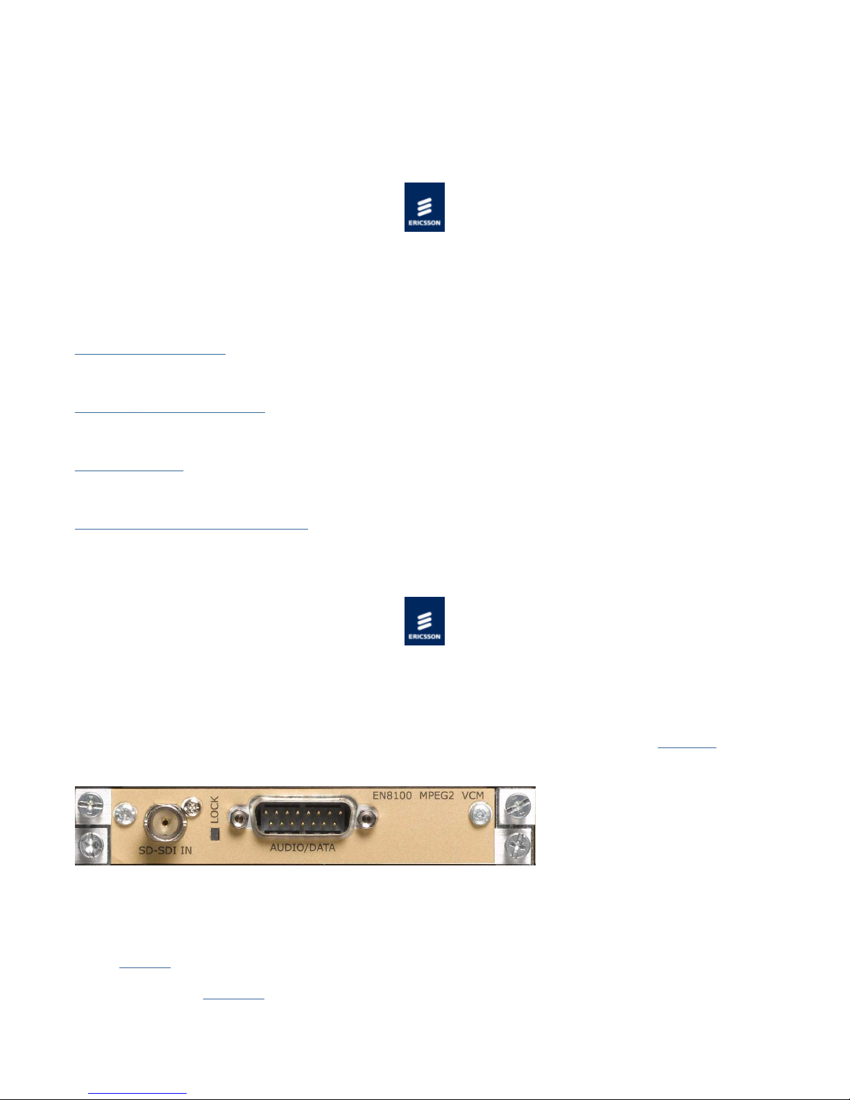
Overview
The EN8100 SD MPEG-2 Video Compression Module (VCM) option card can encode a single standard definition video input using the
MPEG-2 algorithm.
EN8100 SD MPEG-2 VCM Rear Panel
Inputs
The card provides an SDI video input via a BNC connector, and digital audio input via a 15-way D-type connector.
SDI Input via a 75 Ω BNC female connector.
Audio Input via a 15-way D-Type male connector for audio and (see Installing the Equipment> External Interfaces > SD
MPEG-2 VCM > Audio Input)
Page 20

Video
Page
20
of
153
Cover
9/11/2012
file://C:\Users\ebriacl\AppData\Local\Temp\~hh7DF.htm
SDI video input.
Frame re-synchronization.
Programmable bandwidth filter.
Adaptive spatial and temporal noise reduction (software option VP/SWO/SDMP2/NR)
MPEG-2 MP@HL Video Encoding (0.5 to 54 Mbps)
Vertical resolution: 576 or 288 (PAL), 480 or 240 (NTSC)
Horizontal Resolution: 720, 704, 640, 544, 528, 480, 352.
Auto Field/Frame picture encoding.
Auto Concatenation (software option VP/SWO/ACON), Scene Cut Detection, Adaptive GOP Structure and Length.
VBI Data
World Standard Text (WST – ETS300472) (625 line only)
Closed Captions: EIA-608, EIA-708 via SMPTE 334, or line 21.
SMPTE 2016-3 AFD and Bar Data
Wide Screen Signaling (WSS or WSS-AFD)
Monochrome Samples
Audio Compression
Eight channels AES/EBU digital audio input either de-embedded from SDI or via AES/EBU input connector.
Supported audio coding modes:
- MPEG-1 Layer II (32 kbps to 384 kbps)
- Dolby Digital (56 kbps to 640 kbps) (software option VP/SWO/AC3)
- Pass through of pre-encoded Dolby Digital or Dolby Digital Plus
- AAC
- Trasncode from Dolby E
Indications
LED indication for SD SDI lock status (see Installing the Equipment> External Interfaces > SD MPEG-2 VCM > Video Input: LED
Indication).
© Ericsson AB 2011. All rights reserved
EN8130 SD H.264 VCM Module (VP/HWO/EN8130/ENC)
Summary of Features
Video Encoding
Describes the Video processing functionality available in the SD H.264 VCM.
Audio Encoding
Describes the Audio Inputs and Coding Modes provided by the HD H.264 VCM.
Vertical Blanking Interval Coding
Describes the VBI data extraction and processing capabilities of the SD H.264-2 VCM.
© Ericsson AB 2011. All rights reserved
Page 21

Summary of Features
Page
21
of
153
Cover
9/11/2012
file://C:\Users\ebriacl\AppData\Local\Temp\~hh7DF.htm
Overview
The EN8130 SD H.264 Video Compression Module (VCM) option card can encode a single standard definition video input using the
H.264 algorithm.
Inputs
The card provides an SDI video input via a BNC connector, and digital audio input via a 15-way D-type connector.
SDI Input via a 75 Ω BNC female connector.
Audio Input via a 15-way D-Type male connector for audio and (see Installing the Equipment> External Interfaces > SD
MPEG-2 VCM > Audio Input)
Video
SDI video input.
Frame re-synchronization.
Programmable bandwidth filter.
Adaptive spatial and temporal noise reduction (software option VP/SWO/SDMP2/NR)
H.264 Main Profile @ Level 3.0 Video Encoding (0.5 to 10 Mbps)
H.264 High Profile @ Level 3.0 Video Encoding (0.5 to 12.5 Mbps)
Vertical resolution: 576 or 288 (PAL), 480 or 240 (NTSC)
Horizontal Resolution: 720, 704, 640, 544, 528, 480, 352.
VBI Data
World Standard Text (WST – ETS300472) (625 line only)
Closed Captions: EIA-608, EIA-708 via SMPTE 334, or line 21.
SMPTE 2016-3 AFD and Bar Data
Wide Screen Signaling (WSS or WSS-AFD)
Audio Compression
Eight channels AES/EBU digital audio input either de-embedded from SDI or via AES/EBU input connector.
Supported audio coding modes:
- MPEG-1 Layer II (32 kbps to 384 kbps)
- Dolby Digital (56 kbps to 640 kbps) (software option VP/SWO/AC3)
- Pass through of pre-encoded Dolby Digital or Dolby Digital Plus
- AAC
- Trasncode from Dolby E
Indications
LED indication for SD SDI lock status (see Installing the Equipment> External Interfaces > SD MPEG-2 VCM > Video Input: LED
Indication).
© Ericsson AB 2011. All rights reserved
Page 22

EN8130 SD H.264 Video Encoding
Page
22
of
153
Cover
9/11/2012
file://C:\Users\ebriacl\AppData\Local\Temp\~hh7DF.htm
Inputs
SDI Input via 75 ohm BNC connector.
Digital Audio Input via 15 way D-Type connector
Overview
The EN8130 SD H.264 VCM can encode one standard definition video input.
The video input signal is processed in to a compressed encoded bit-stream in accordance with the H.264 specification (ITU-T H.264
or ISO/IEC MPEG4 AVC).
A constant bit rate (CBR) output can be produced and may be set to between 0.5Mbps and 12.5 Mbps, depending upon the
configured encoding profile. The card can also produce a variable bit rate output when operating as part of a Reflex statistical
multiplexing system.
Video Compression Functionality
The following is a summary of the Video Compression functionality available from the EN8190 HD H.264 VCM.
Function Comments
H.264 Main Profile @ Level 3.0 encoding
H.264 High Profile @ Level 3.0 encoding
Variable Seamless Mode
Support for a constant bit rate mode
Support for current reflex mode (look ahead
mode 4)
Video Input 720x576, 25 Hz
Video Input 720x480, 29.97 Hz
Output resolutions 720, 704, 640, 544, 528,
480, 352 X 576/480 352 X 288/240
See Transport Stream Output Overview for transport stream rates.
Support for different resolutions including the standard set of video
picture resolutions for both 625 (576/288 PAL) and 525 (480/240
NTSC) line operation.
Test Patterns
The video pre-processor has the facility to generate a test pattern.
Loss of Video Input
On loss of video input, the SD H.264 VCM can be configured to select one of the default test patterns or a freeze frame as the
output. It is also possible to configure it to stop generating the compressed video component on loss of the video input.
Impairment Reduction
The video pre-processor provides spatial/temporal noise reduction which is motion adaptive.
Impairment Reduction Comments
Motion Compensated Temporal Filtering
© Ericsson AB 2011. All rights reserved
Only available if license VP/SWO/SD/MCTF has
been purchased.
Page 23

EN8180 HD MPEG-2 VCM Module (VP/HWO/EN8180/ENC)
Page
23
of
153
Cover
9/11/2012
file://C:\Users\ebriacl\AppData\Local\Temp\~hh7DF.htm
Summary of Features
Video Encoding
Describes the Video processing functionality available in the HD MPEG-2 VCM.
Audio Encoding
Describes the Audio Inputs and Coding Modes provided by the HD MPEG-2 VCM.
Vertical Blanking Interval Coding
Describes the VBI data extraction and processing capabilities of the HD MPEG-2 VCM.
© Ericsson AB 2011. All rights reserved
Summary of Features
Overview
The EN8180 HD MPEG-2 Video Compression Module (VCM) option card can encode a single high or standard definition video input
using the MPEG-2 algorithm.
Inputs
The card provides an HD-SDI video input via a BNC connector, and digital audio input via a 15-way D-type connector.
HD-SDI Input via a 75 Ω BNC female connector.
Audio Input via a 15-way D-Type male connector for audio and (see Installing the Equipment> External Interfaces > HD
H.264 VCM > Audio Input)
Video
SDI video input.
Frame re-synchronization.
Programmable bandwidth filter.
Motion Compensated Temporal Filtering (software option VP/SWO/HD/MCTF)
MPEG-2 MP@ML Video Encoding (0.256 to 15 Mbps)
1080i x 1920, 1080i x 1440 output resolution
720P x 1260, 720P x 960 output resolution.
Scene cut detection
Ancillary Data
Closed Captions: EIA-608, EIA-708 via SMPTE 334.
Time Code
Generic VANC carriage (SMPTE 2038)
Audio Compression
Eight channels AES/EBU digital audio input either de-embedded from HD-SDI or via AES/EBU input connector.
Supported audio coding modes:
- MPEG-1 Layer II (32 kbps to 384 kbps)
Page 24

- Dolby Digital (56 kbps to 640 kbps) (software option VP/SWO/AC3)
Page
24
of
153
Cover
9/11/2012
file://C:\Users\ebriacl\AppData\Local\Temp\~hh7DF.htm
- Pass through of pre-encoded Dolby Digital or Dolby Digital Plus
- AAC
- Transcode from Dolby E
Indications
LED indication for SDI lock status (see Installing the Equipment> External Interfaces > SD MPEG-2 VCM > Video Input: LED
Indication).
© Ericsson AB 2011. All rights reserved
EN8180 HD MPEG-2 Video Encoding
Inputs
HD-SDI Input via 75 ohm BNC connector.
Digital Audio Input via 15 way D-Type connector
Overview
The EN8190 HD H.264 VCM can encode one high definition video input.
The video input signal is processed in to a compressed encoded bit-stream in accordance with the H.264 specification (ITU-T H.264
or ISO/IEC MPEG4 AVC).
A constant bit rate (CBR) output can be produced and may be set to between 1Mbps and 25 Mbps, depending upon the configured
encoding profile. The card can also produce a variable bit rate output when operating as part of a Reflex statistical multiplexing
system.
Video Compression Functionality
The following is a summary of the Video Compression functionality available from the EN8190 HD H.264 VCM.
Function Comments
MPEG-2 MP@ML encoding
MPEG-2 MP@HL encoding
Variable Seamless Mode
Support for a constant bit rate mode
Support for current reflex mode (look ahead
mode 4)
Video Input 720x576, 25 Hz
Video Input 720x480, 29.97 Hz
Video Input 1080x1920, 25/29.97 Hz
Video Input 720x1280, 50/59.94 Hz
See Transport Stream Output Overview for transport stream rates.
Test Patterns
The video pre-processor has the facility to generate a test pattern.
Loss of Video Input
On loss of video input, the HD H.264 VCM can be configured to select one of the default test patterns or a freeze frame as the
output. It is also possible to configure it to stop generating the compressed video component on loss of the video input.
Impairment Reduction
Page 25

The video pre-processor provides spatial/temporal noise reduction which is motion adaptive.
The VCM aligns VBI data and compressed video frames within the bounds dictated by time stamping of received data, i.e. stamp the
Page
25
of
153
Cover
9/11/2012
file://C:\Users\ebriacl\AppData\Local\Temp\~hh7DF.htm
Impairment Reduction Comments
Noise Reduction (motion adaptive)
See also Technical Specification > HD H.264 VCM > Video > Impairment Reduction.
© Ericsson AB 2011. All rights reserved
Only available if license VP/SWO/HD/MCTF has
been purchased.
Vertical Blanking Interval (VBI) Data
General
All VBI information carriage are configurable (either enabled or disabled). The video line from which the VBI is extracted is
configurable. The default is set according to the recognised standard for the VBI type.
VBI Lines
Up to at least 8 VBI lines per field can be extracted. Unless otherwise stated, all VBI data are formed into one VBI transport stream
packet that conforms to ETSI EN 301 775 or SCTE 127.
VBI Data
Data can be extracted from the vertical blanking interval of the incoming video stream, processed, and then included in the output
transport stream.
The following is a summary of the VBI Data functionality available from the unit.
Component Comments
Video Index It is possible to extract video index and another VBI type from the same line.
Closed Captions
Teletext Up to 18 lines can be extracted per field.
Aspect Ratio Signalling WSS/WSS-AFD/AFD/AFD and Bar Data via VANC
Via line 21 & 284 (CEA-608C) or SMPTE 334 (extracted from VANC data - 525
Line only).
VBI Data on a Separate PID
The VBI data is packetised within MPEG-2 PES packets as specified in ETSI ETS 300-472 (teletext), ETSI EN 301 775 or SCTE 127
for all other VBI data.
Refer to Transport Stream Output > VBI Data on a Separate PID for more information.
Closed caption data, and aspect ratio signalling can also be inserted in to the compressed video elementary stream.
Timing
same PTS on the video and VBI that came in on the same frame.
© Ericsson AB 2011. All rights reserved
HD Ancillary Data Processing
General
Page 26

Specific Ancillary (ANC) Data types can be configured on/off, to be extracted from the HD-SDI input and carried as specified
47 and carried
Page
26
of
153
Cover
9/11/2012
file://C:\Users\ebriacl\AppData\Local\Temp\~hh7DF.htm
depending upon the data type.
ANC Data
The following is a summary of the ANC Data functionality available from the unit.
Component Comments
Closed Captions
Generic VANC
Time Code
OP-47 (Subtitles)
© Ericsson AB 2011. All rights reserved
Via SMPTE 334 (extracted from VANC data - 29.97Hz operation only) and
carried in the 'Picture User data' (user_data_registered_itu_t_t35 SEI
message) of the video stream as per ATSC A/72 part 1
Up to 2 MBit/s of ANC data (excluding embedded audio) can be extracted and
carried in the VBI component as defined in SMPTE 2038.
Via SMPTE 12-2 (extracted from VANC data) and carried in the elementary
stream (in the pic_timing SEI message) and the transport stream adaptation
layer as per ETSI TS101 154
Teletext subtitles are extracted from ANC in accordance with OPin a teletext PID.
EN8190 HD H.264 VCM Module (VP/HWO/EN8190/ENC)
The HD H.264 VCM has a unique processing engine that extracts the maximum efficiency possible from the H.264 specification.
Summary of Features
Video Encoding
Describes the Video processing functionality available in the HD H.264 VCM.
Audio Encoding
Describes the Audio Inputs and Coding Modes provided by the HD H.264 VCM.
HD Ancillary Data Procssing
Describes the ANC data extraction and processing capabilities of the HD H.264 VCM.
© Ericsson AB 2011. All rights reserved
Summary of Features
Overview
The EN8190 HD H.264 Video Compression Module (VCM) is a 2 card solution to provide an option to encode a single high definition
video input using the H.264 algorithm.
Page 27

Page
27
of
153
Cover
9/11/2012
file://C:\Users\ebriacl\AppData\Local\Temp\~hh7DF.htm
EN8190 HD H.264 VCM Rear Panel
Inputs
The card provides an HD-SDI video input via a BNC connector, and digital audio input via a 15-way D-type connector.
HD-SDI Input via a 75 Ω BNC female connector.
Audio Input via a 15-way D-Type male connector for audio and (see Installing the Equipment> External Interfaces > HD
H.264 VCM > Audio Input)
Video
HD-SDI video input.
Frame re-synchronization.
Programmable bandwidth filter.
H.264 Main Profile @ Level 4.0 Video Encoding (1 to 20 Mbps)
H.264 High Profile @ Level 4.0 Video Encoding (1 to 25 Mbps)
1080i x 1920, 1080i x 1440 output resolution
720P x 1260, 720P x 960 output resolution.
Scene cut detection
Ancillary Data
Closed Captions: EIA-608, EIA-708 via SMPTE 334.
Time Code
Generic VANC carriage (SMPTE 2038)
Audio Compression
Eight channels AES/EBU digital audio input either de-embedded from HD-SDI or via AES/EBU input connector.
Supported audio coding modes:
- MPEG-1 Layer II (32 kbps to 384 kbps)
- Dolby Digital (56 kbps to 640 kbps) (software option VP/SWO/AC3)
- Pass through of pre-encoded Dolby Digital or Dolby Digital Plus
- AAC
- Transcode from Dolby E
Indications
LED indication for HD SDI lock status (see Installing the Equipment> External Interfaces > HD H.264 VCM > Video Input: LED
Indication).
© Ericsson AB 2011. All rights reserved
EN8190 HD H.264 Video Encoding
Page 28

Inputs
Page
28
of
153
Cover
9/11/2012
file://C:\Users\ebriacl\AppData\Local\Temp\~hh7DF.htm
HD-SDI Input via 75 ohm BNC connector.
Digital Audio Input via 15 way D-Type connector
Overview
The EN8190 HD H.264 VCM can encode one high definition video input.
The video input signal is processed in to a compressed encoded bit-stream in accordance with the H.264 specification (ITU-T H.264
or ISO/IEC MPEG4 AVC).
A constant bit rate (CBR) output can be produced and may be set to between 1Mbps and 25 Mbps, depending upon the configured
encoding profile. The card can also produce a variable bit rate output when operating as part of a Reflex statistical multiplexing
system.
Video Compression Functionality
The following is a summary of the Video Compression functionality available from the EN8190 HD H.264 VCM.
Function Comments
H.264 Main Profile @ Level 4.0 encoding
H.264 High Profile @ Level 4.0 encoding
Variable Seamless Mode
Support for a constant bit rate mode
Support for current reflex mode (look ahead
mode 4)
Video Input 1080x1920, 25/29.97 Hz
Video Input 720x1280, 50/59.94 Hz
See Transport Stream Output Overview for transport stream rates.
Test Patterns
The video pre-processor has the facility to generate a test pattern.
Loss of Video Input
On loss of video input, the HD H.264 VCM can be configured to select one of the default test patterns or a freeze frame as the
output. It is also possible to configure it to stop generating the compressed video component on loss of the video input.
Impairment Reduction
The video pre-processor provides spatial/temporal noise reduction which is motion adaptive.
Impairment Reduction Comments
Noise Reduction (motion adaptive)
See also Technical Specification > HD H.264 VCM > Video > Impairment Reduction.
© Ericsson AB 2011. All rights reserved
Only available if license VP/SWO/HD/MCTF has
been purchased.
ASI Option Module (VP/HWO/ASI/2IN2OUT)
The ASI option module provides two 75 Ω female BNC output connectors to provide the option to transmit a transport stream
generated by the base chassis over ASI.
Page 29
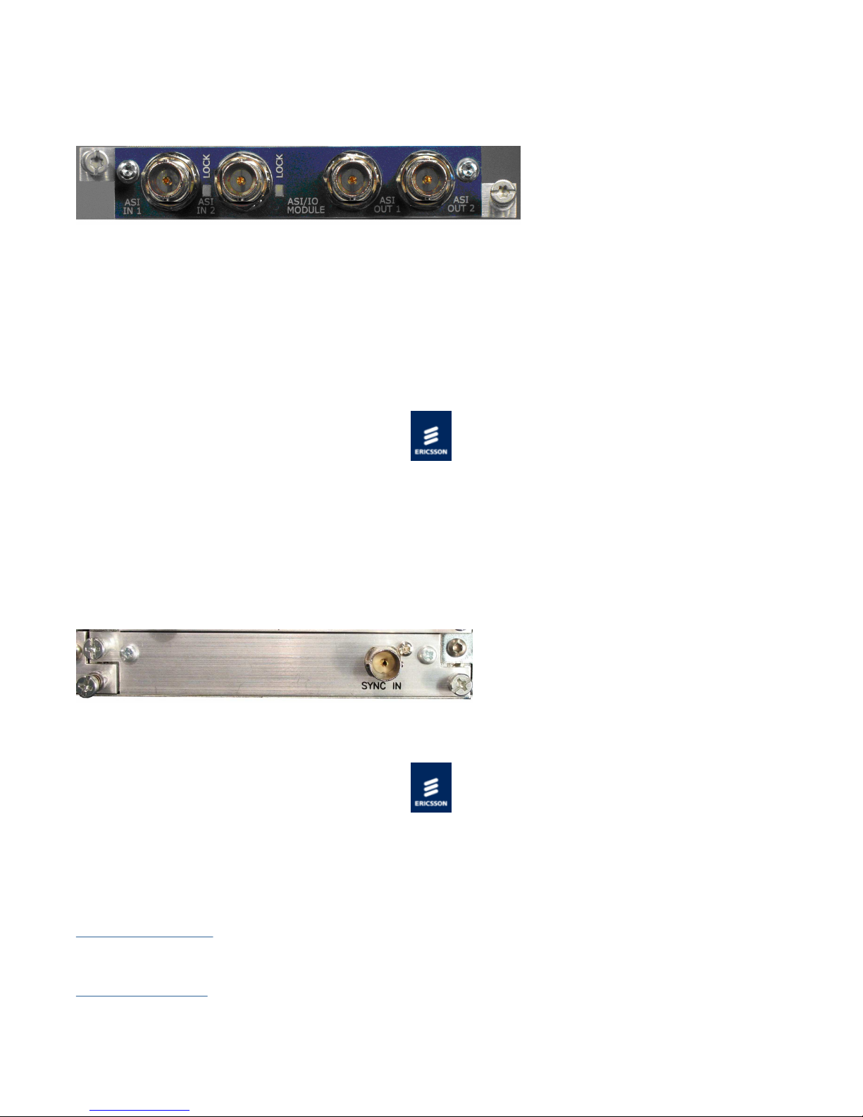
Note...
ASI Option Module Rear Panel
Page
29
of
153
Cover
9/11/2012
file://C:\Users\ebriacl\AppData\Local\Temp\~hh7DF.htm
In this release the ASI outputs are mirrored - the same transport stream is transmitted from both outputs.
Two 75 Ω female BNC input connectors are also available but are not supported in this release.
The ASI option module uses the 27MHz clock and System Reference Clock (SRC) from the base chassis backplane as its frequency
reference.
The output bit rate of the ASI Card is configurable up to 216Mbps. The module automatically determines if the packets are to be
sent either in Burst or Byte Mode. If the TS rate is less than 70Mbps, packets are sent in byte mode. Above 70Mbps burst mode is
used.
© Ericsson AB 2011. All rights reserved
External Sync Input
The External Sync Input card provides a 75 Ω female BNC connector to allow an external synchronization signal to be input to the
unit. This signal may then be used as the frequency reference for the units 27 MHz System Clock Reference.
The input signal may either be:
1 V peak to peak PAL or NTSC black and burst video signal.
1 V peak to peak 10 MHz square wave or sine wave reference.
Sync Option Input Module Rear Panel
© Ericsson AB 2011. All rights reserved
Installing the Equipment
This chapter provides a guide to the suitability of an installation and gives detailed procedures for the preparation and installation of
the equipment. Also details the external connectors and provides important safety information.
Preliminary Checks
Gives general information relating to Mechanical Inspection of the unit and how to move it safely.
Site Requirements
Describes the requirements for powering the unit and the need for lightning protection (if required).
Page 30

Mounting in a Rack
When taking delivery of an Encoder, check the equipment items delivered against the enclosed delivery note. Inspect the equipment
Page
30
of
153
Cover
9/11/2012
file://C:\Users\ebriacl\AppData\Local\Temp\~hh7DF.htm
Gives information associated with fixing the unit into a rack and the care and positioning of cables.
External Interfaces
Describes the connectors relating to the basic unit and any option modules.
© Ericsson AB 2011. All rights reserved
Preliminary Checks
Mechanical Inspection
for damage-in-transit. If in doubt, please contact Customer Services.
Removing the covers of this equipment may invalidate any warranties, cause a safety hazard or/and affect the EMC performance.
Check with Customer Services.
WARNING!
Moving the Equipment Safely
Do not place this product on an unstable cart, stand, bracket, or table. The product may fall, causing serious injury and serious
damage to the product. Use only with a cart, stand, bracket or table recommended by Ericsson.
An appliance and cart combination should be moved with care. Quick stops, excessive force, and uneven surfaces may cause the
appliance and cart combination to overturn.
Do not move or carry the equipment whilst it is still connected to the supply or other leads, is live or is in operation.
See, also:
The Handling and Lifting section in Read This First!
Appendices > Handling Option Cards > Handling Option Cards
© Ericsson AB 2011. All rights reserved
Site Requirements
This chapter provides a guide to the suitability of an installation and gives detailed procedures for the preparation and installation of
the equipment. Also details the external connectors and provides important safety information.
AC Power Supply
Gives information relating to the AC power inlet and associated components.
Power Consumption
Details the power consumption of the base chassis and each option card.
Page 31

Protective and Technical Earths
AC Power Receptacles
type to your business, consult your appliance dealer or local power company. Do not overload wall outlets and extension cords as
Page
31
of
153
Cover
9/11/2012
file://C:\Users\ebriacl\AppData\Local\Temp\~hh7DF.htm
Describes the requirements for earthing the unit.
Lightning Protection
This topic discusses the requirement of lightning protection (when appropriate).
© Ericsson AB 2011. All rights reserved
AC Power Supply
Variants
This Handbook covers two Base Chassis; a single AC PSU version, and a dual AC PSU version.
[Single AC PSU] [Dual AC PSU]
Specification
The equipment operates from an wide-ranging mains power supply (100-240 V AC 50/60 Hz nominal) and is designed for use in
ambient air temperature in the range 0°C to +50°C. There are no links etc. to be altered for operation from different supply
voltages. The full Technical Specification is given in Technical Specification > Chassis [Host] > Power Supplies.
The following points regarding power connection must be adhered to ensure safe operation of the equipment.
The equipment should only be operated from the type of power source indicated on the marking label. If you are not sure of the
Dual AC Power
WARNING!
this can result in a risk of fire or electric shock.
The equipment is not fitted with an AC Power On/Off switch. Ensure the supply socket outlet is installed or located near the
equipment so that it is accessible.
Remove both sources of mains power to the dual PSU version before removing covers or moving the equipment.
Supply Cord
A two-metre mains supply cord is supplied with this product. It is fitted with a moulded plug suitable for the USA, UK or mainland
Europe as advised at the time of ordering.
Wire Colours
The wires in the supplied cord are coloured as follows:
Page 32

The terminal marked at the rear panel is a Technical Earth. Its use is recommended. This is NOT a protective earth for electric shock
UK (BS 1363) EUROPE (CEE 7/7) USA (NEMA 5-15P)
Page
32
of
153
Cover
9/11/2012
file://C:\Users\ebriacl\AppData\Local\Temp\~hh7DF.htm
Earth Green and yellow Green and yellow Green
Neutral Blue Blue White
Live Brown Brown Black
Connecting the Equipment to the AC Power Supply
As there is no mains power switch fitted to this chassis, ensure the local AC power supply is switched OFF before connecting the
supply cord.
Connect the mains lead to the equipment and then to the local supply.
© Ericsson AB 2011. All rights reserved
Power Consumption
Rated current 4.0 – 2.0 A
Power consumption: 350W (Actual power consumption is dependant on the option cards fitted, see Table of Typical Power
Consumption).
Typical Power Consumption
Item Description
VP/CHASSIS/1AC 1U Base Chassis (AC) 40 W
VP/CHASSIS/2AC 1U Base Chassis (Dual AC) 45 W
VP/HWO/EN8190/ENC EN8190 HD H.264 VCM 120W
VP/HWO/EN8100/ENC EN8100 SD MPEG-2 VCM 45 W
VP/HWO/EN7100/ENC EN7100 SD MPEG-2 VCM 45 W
VP/HWO/EN8130/ENC EN8130 SD H.264 VCM 40 W
VP/HWO/EN8180/ENC EN8180 HD MPEG-2 VCM 40 W
VP/HWO/ASI2IN2OUT ASI I/O Module 12 W
VP/HWO/EXTSYNC External Sync Option Module 0.2 W
See also Technical Specification>Chassis>Power Supplies, Technical Specification>* VCM>Power Supplies.
© Ericsson AB 2011. All rights reserved
Power
Protective and Technical Earths
Protective Earth
This unit must be correctly earthed as described below.
This unit must be correctly earthed through the moulded plug supplied. If the local mains supply does not have an earth
conductor do not connect the unit. Contact Customer Services for advice.
Before connecting the unit to the supply, check the supply requirements.
Technical Earth
protection.
WARNING!
Page 33

Where appropriate, ensure this product has an adequate level of lightning protection. Alternatively, during a lightning storm or when
it is left unattended and unused for long periods of time, unplug it from the supply outlet and disconnect the output equipment. This
Page
33
of
153
Cover
9/11/2012
file://C:\Users\ebriacl\AppData\Local\Temp\~hh7DF.htm
Technical Earth
The Technical Earth provides a suitable connection between the equipment and the installation to give a low impedance path at
normal operating frequencies.
The terminal is provided to:
Ensure all equipment chassis fixed within a rack are at the same technical earth potential.
Eliminate the migration of stray charges when connecting between equipment.
To do this, connect a wire between the Technical Earth terminal and a suitable point on the rack.
It is strongly recommended that the earth terminal at the rear panel of the equipment is connected to a site Technical Earth before
any external connections are made and the equipment is powered. This limits the migration of stray charges.
© Ericsson AB 2011. All rights reserved
CAUTION!
Lightning Protection
If the equipment has been subject to a lightening strike or power surge, which has stopped it working, disconnect the power
immediately, do not re-apply power until it has been checked for safety. If in doubt, contact Customer Services.
prevents damage to the product due to lightning and power line surges.
© Ericsson AB 2011. All rights reserved
WARNING!
Mounting in a Rack
Page 34

Gives information associated with fixing the unit into a rack and the care and positioning of cables.
protective package until you
Page
34
of
153
Cover
9/11/2012
file://C:\Users\ebriacl\AppData\Local\Temp\~hh7DF.htm
Installing the Equipment
Read This First: Read the information contained in this topic before beginning to install the equipment.
Care in Positioning
This topic describes what needs to be considered before fixing the unit into a rack.
Fixing
Provides information related to the fixing of the unit in a rack.
Cable Types/Installing Cables
Tabulates the recommended cables required to maintain EMC compliance. Also describes the care required when installing the
cables.
© Ericsson AB 2011. All rights reserved
Handling and Lifting
Handling the Equipment
The equipment must be handled and installed carefully and thoughtfully to prevent safety hazards and damage.
Lifting
In some circumstances the unit might be awkward to lift. In which case, do not attempt to lift or move it without proper assistance
or equipment. If in doubt, seek assistance.
Electrostatic Handling
Static electricity can damage electronic components. To avoid damage, keep option cards in their staticare ready yo install them.
Refer to Options Cards for information relating to the handling of Option Modules.
WARNING!
Installing the Equipment
Read the comments in Read This First before starting work.
© Ericsson AB 2011. All rights reserved
Care in Positioning
Positioning the Unit
Page 35

CAUTION!
Airflow Through the Unit
Page
35
of
153
Cover
9/11/2012
file://C:\Users\ebriacl\AppData\Local\Temp\~hh7DF.htm
The following points must be taken in to consideration when positioning the unit.
The fans contained within this unit are not fitted with a dust/insect filter. Pay attention to the environment in which it is to be
used.
Do not install units so that the air intake of one aligns with the outlet on another. Provide baffles and adequate spacing.
The equipment should never be placed near or over a radiator or other source of heat. It should not be placed in a built-in
installation such as a rack unless proper ventilation is provided and the instructions have been adhered to.
Allow at least 40 mm free air-space at each side of the equipment to ensure adequate cooling.
Racks containing stacked equipment may need to be forced air-cooled to reduce the ambient temperature within the rack.
Protection from Moisture
Do not install this equipment in areas of high humidity or where there is a danger of water ingress.
Cooling
Side openings in the unit, as well as side-mounted cooling fans, are provided for ventilation. They ensure reliable operation of the
product and protect it from overheating.
The ventilation openings must not be blocked or covered.
© Ericsson AB 2011. All rights reserved
WARNING!
Fixing
Overview
The equipment is designed for fixed use only and has been shipped with fixing brackets suitable for a standard 19-inch rack. When
installed in a rack, it should be secured using the fixing brackets. In addition, support shelves must be used to reduce the weight on
the brackets. Ensure it is firmly and safely located and it has an adequate flow of free-air.
Fixing the Unit
Slide the unit onto the chassis supports and affix to the rack by means of an M6 x 18 mm panhead screw in each corner.
A freestanding unit should be installed on a secure horizontal surface where it is unlikely to be knocked or its connectors and leads
disturbed.
© Ericsson AB 2011. All rights reserved
Cable Types/Installing Cables
Page 36

Cable Types
Page
36
of
153
Cover
9/11/2012
file://C:\Users\ebriacl\AppData\Local\Temp\~hh7DF.htm
The signal cable types (or similar) described in the following table are those recommended by Ericsson in order to maintain product
EMC compliance.
Signal Type Connector Cable
Ethernet (Control) RJ-45 Alcatel Data Cable FTP 7 x 0.16
Ethernet (Data) RJ-45 Cat 5e Belden Datatwist (S-FTP)
HD-SDI In (Video Input) BNC Canford Audio BBC 1/3 PSF
SDI In (Video Input) BNC Canford Audio BBC 1/3 PSF
Digital Audio D-Type Canford Audio DFT
Ext Sync BNC Canford Audio BBC 1/3 PSF
ASI Output BNC Canford Audio BBC 1/3 PSF (type 2 video cable)
Installing Cables – Safely
Power supply cables should be routed so that they are not likely to be walked on or pinched by items placed upon or against them.
Pay particular attention to cables at plugs, convenience receptacles, and the point where they exit from the appliance.
Do not run AC power cables in the same duct as signal leads.
Do not move or install equipment whilst it is still attached to the mains supply.
Ensure safety and ESD precautions are observed whilst inter-connecting equipment.
© Ericsson AB 2011. All rights reserved
External Interfaces
Describes the connectors and visual indicators associated with each component of the equipment.
Base Chassis
Identifies and describes each connector and indicator associated with the Chassis.
EN7100 and EN8100 SD MPEG-2 VCM
Identifies and describes each connector and indicator associated with the SD MPEG-2 VCM.
EN8180 and EN8190 HD H.264 VCM
Identifies and describes each connector and indicator associated with the HD H.264 VCM.
ASI Option Module
Identifies and describes each connector and indicator associated with the ASI Option Module.
External Sync Module
Identifies and describes each connector and indicator associated with the External Sync Module.
© Ericsson AB 2011. All rights reserved
Page 37

Chassis/Host
Page
37
of
153
Cover
9/11/2012
file://C:\Users\ebriacl\AppData\Local\Temp\~hh7DF.htm
General
Identifies the position of the connectors and indicators at the front and rear panels and what combinations of external interfaces are
supported.
Control Ethernet
Identifies the Ethernet Control ports located at the rear panel of the chassis and tabulates the connectors' pinout. Describes the
operation of each port, and the Status and Activity indicators.
Data Ethernet
Identifies the Ethernet Data ports located at the rear panel of the chassis and tabulates the connectors' pinout. Describes the
operation of each port, and the Status and Activity indicators.
AC Input Connector
Shows the rear panel AC connector and provides fusing information.
USB Connector
Provides information associated with the USB connector located at the front panel.
© Ericsson AB 2011. All rights reserved
General
External Interfaces
The following combinations of external interfaces are supported by the chassis, (i.e. without the interface being provided by an
option card):
Chassis
Option
AC ●
IP
AC Input
1 ‘RU’ Base Chassis Single PSU Rear Panel
It is strongly recommended that the terminal marked at the rear panel of the equipment is connected to a site Technical Earth
before any external connections are made and the equipment is powered. This limits the migration of stray charges.
Data Ethernet
Ethernet Control Ethernet Data
#1 #2 #1 #2 #3 #4
● ● ● ● ● ● ●
WARNING!
USB
Test/Maintenance
Page 38

Control Ethernet AC Input
Page
38
of
153
Cover
9/11/2012
file://C:\Users\ebriacl\AppData\Local\Temp\~hh7DF.htm
Location of the Ethernet and Single AC Connectors at the Rear Panel
All signal connections are made via the rear panel.
NOTE : Single A.C. PSU version shown.
Front Panel
Identifying Items Located at the Front Panel
The front panel provides a 2 line by 40 character display, 6 buttons, and a red/amber/green tri-colour status LED.
Items on the Front Panel
LCD
Control and status information is displayed on a 2 line by 40 character display.
Buttons
Six buttons are provided for navigating through the front panel menus. See Front Panel Controls and Pushbuttons for more details.
Status LED
An LED located at the front panel gives an indication of the status of the unit.
LED State Unit Status
Off Unit not powered
Green No active warnings or alarms
Amber Active warning/s, minor or major alarm/s
Red Active critical alarm/s
USB Connector
This is not for customer use. Please refer to USB connector.
1 ‘RU’ Base Chassis Dual PSU Rear Panel
This chassis is the same as the 1 ‘RU’ Base Chassis but with the dual PSU.
Data Ethernet
Control Ethernet AC Input
Location of the Ethernet and Dual AC Connectors at the Rear Panel (Blanking Plates Fitted)
Page 39

Page
39
of
153
Cover
9/11/2012
file://C:\Users\ebriacl\AppData\Local\Temp\~hh7DF.htm
A technical specification for the connections is given in Technical Specification > Base Chassis.
© Ericsson AB 2011. All rights reserved
Control Ethernet
Overview
The Ethernet control ports are used to connect the equipment to nCompass Control [V6.5 on] or to a PC for access to the web
browser.
Ethernet Ctrl Port Numbering
Both connectors share the same IP address, Ctrl1 is the Primary control port, and is by default the active control port. Control Port
Ctrl2 should be considered as the secondary control network as it will not respond to the Control Port IP Address unless control has
been passed to it either as a result of a redundancy switch, or via a user command. The active control port switches when Ctrl1 has
no link (e.g. carrier), and Ctrl2 has the link.
Refer to:
Operation and Control >Basic Functions > Ethernet: Control for Control Port Parameters.
Item Specification
Connector type RJ-45 (100/1000 Base T)
Connector designation Ctl 1/2
Pin outs
(Unused pins are not connected)
Pin 1 - Tx Out(+)
Pin 2 - TX Out (-)
Pin 3 - Rx In (+)
Pin 6 - RX Out (-)
Status and Activity Indication
Each Ethernet Control Port has a rear panel mounted status LEDs associated with it to indicate link status, activity and speed as
follows:
Left (Green) LED
Port Status Link Speed LED Status
— — — — — — — — — — — — — — —
— — —
— ☐ — ☐ ☐ ☐ ☐ ☐ ☐ — ☐ — ☐ ☐ ☐
☐ ☐ ☐ ☐
Active Port
No Link Off
100 Mbps Flash Off x 2
1000 Mbps Flash Off x 3
— ☐ — ☐ — ☐ ☐ ☐ ☐ — ☐ — ☐ — ☐
Page 40

☐ ☐ ☐ ☐
Page
40
of
153
Cover
9/11/2012
file://C:\Users\ebriacl\AppData\Local\Temp\~hh7DF.htm
No Link Off
Spare Port
The Right LED flash sequence period is 1 s, with the short flash duration being 100 ms.
Right (Yellow) LED
Link Activity LED Status
No Link Off
Link
Activity
© Ericsson AB 2011. All rights reserved
100 Mbps Flash On x 2
1000 Mbps Flash On x 3
— — — — — — — — — — — — — — — — — —
On
Flash
☐ ☐ ☐ ☐ ☐ ☐ ☐ ☐ ☐ ☐ ☐ ☐ ☐ ☐ ☐ ☐ ☐ ☐ ☐
— ☐ — ☐ — ☐ ☐ ☐ ☐ ☐ — ☐ — ☐ ☐ — ☐ ☐ —
— — — — — — — — — — — — — — —
— — —
☐ — ☐ — — — — — — ☐ — ☐ — — —
— — —
☐ — ☐ — ☐ — — — — ☐ — ☐ — ☐ —
— — —
Data Ethernet
Overview
The unit has four Ethernet ports for data output and will respond to ARPs, pings and Reflex PCR exchange messages for statistical
multiplexing. The input of other data is NOT supported. The ports are accessible via RJ-45 connectors on the rear panel of the
chassis. These are labeled Ge 1, Ge 2, Ge 3 and Ge 4.
Data Port Numbering
Item Specification
Connector type RJ-45 (100/1000 Base T)
Connector designation Ge 1 /2 Ge 3 /4
Pin 1 - Tx Out(+)
Pin outs
Pin 2 - TX Out (-)
Page 41

(Unused pins are not connected) Pin 3 - Rx In (+)
Page
41
of
153
Cover
9/11/2012
file://C:\Users\ebriacl\AppData\Local\Temp\~hh7DF.htm
Pin 6 - RX Out (-)
Status and Activity Indication
Each Ethernet Data Port has a rear panel mounted status LED associated with it to indicate link status, activity and speed as follows:
Left (Green)
LED
Link Speed LED Status
No Link Off
100 Mbps Flash Off x 2
1000 Mbps Flash Off x 3
The left LED flash sequence period is 1 s, with the short flash duration being 100 ms.
Right (Yellow) LED
Link Activity LED Status
No Link Off
Link
Activity Flash
Refer to:
Operation and Control > Ethernet Data for Control Port Parameters.
Appendices > Technical Specification > Chassis (Host) > Data Ethernet Specification for the electrical characteristics.
© Ericsson AB 2011. All rights reserved
On
— — — — — — — — — — — — — — — — — —
— ☐ — ☐ ☐ ☐ ☐ ☐ ☐ — ☐ — ☐ ☐ ☐ ☐ ☐ ☐
☐
— ☐ — ☐ — ☐ ☐ ☐ ☐ — ☐ — ☐ — ☐ ☐ ☐ ☐
☐
— — — — — — — — — — — — — — — — — —
☐ ☐ ☐ ☐ ☐ ☐ ☐ ☐ ☐ ☐ ☐ ☐ ☐ ☐ ☐ ☐ ☐ ☐
☐
— ☐ — ☐ — ☐ ☐ ☐ ☐ ☐ — ☐ ☐ ☐ — ☐ ☐ ☐
Power Requirements
AC Connector
The AC input connector is as follows:
Item Description/Specification
Connector Mains input filter with CEE 22/IEC320 plug
Fusing Fuse in live conductor in mains input filter
Fuse type Time delay (T) 1500 A High breaking capacity (HBC)
Page 42

AC Power Inlets
Page
42
of
153
Cover
9/11/2012
file://C:\Users\ebriacl\AppData\Local\Temp\~hh7DF.htm
AC Power
AC Input
Refer to:
Technical Specification > Base Chassis > Power Supply
Installing the Equipment > Site Requirements > AC Power Supply
Installing the Equipment > External Interfaces > Base Chassis > AC Input Connector
© Ericsson AB 2011. All rights reserved
USB Connector
The USB connector on the front panel of the unit is not for customer use.
USB Connector
This connector is only used for Test/Maintenance purposes.
© Ericsson AB 2011. All rights reserved
EN7100 and EN8100 External Interfaces
Video Input
SDI Input
Standard definition digital video can be input via the 75 ohm female BNC connector labeled SD-SDI on the rear panel.
See Technical Specification > SD MPEG-2 VCM for further details.
Page 43

The picture alongside shows the Video input connector: SD-SDI 75 Ω
at the module rear panel) is used to show the
Page
43
of
153
Cover
9/11/2012
file://C:\Users\ebriacl\AppData\Local\Temp\~hh7DF.htm
female BNC socket at the module rear panel.
Also illustrated is the LED indication for SD SDI lock status.
The LED (marked LOCK
status of the module and/or incoming video signal.
SD-SDI Input and LOCK Indicator at the Rear Panel
LED State Description
LED State Description
Off The SDI Input is not active.
Red The SDI Input is active, but not locked.
Green The SDI Input is active and is locked.
Alternate Red and Green
The SDI Input is active, but video of the wrong line standard is being
received.
Audio Input
Digital Support
Digital audio may be input via the 15-way D-type connector labelled AUDIO/DATA.
The 15-way D-type supports digital audio balanced and
unbalanced signals (but not at the same time).
15-way D-type at the Rear Panel
See Technical Specification for further details.
Breakout Cables
The digital audio can either be balanced (AES3) or unbalanced (AES3-id) depending upon the audio breakout cable used:
Marketing Code Part Number Supported Audio Mode
Balanced Audio: 4 XLRs in + 1 BNC for ref tone
VP/CAB/BAL S14936 Audio Breakout Cable
VP/CAB/UNBAL S14937 Audio Breakout Cable
NOTE : An audio breakout cable is NOT supplied as standard with the chassis, but must be ordered separately.
The chassis detects which cable is fitted (balanced or unbalanced) and selects appropriately.
AES3 AES-3id
Interface Balanced Unbalanced
Connector XLR-3 BNC
Impedance 110 Ω 75 Ω
Input Level 2-7 V peak to peak 1 V peak to peak
out
Unbalanced Audio: 4 BNCs in + 1 BNC out for ref
tone out
Page 44

Max Input 7 V peak to peak 1.2 V peak to peak
Page
44
of
153
Cover
9/11/2012
file://C:\Users\ebriacl\AppData\Local\Temp\~hh7DF.htm
Max Current 64 mA 1.6 mA
Min Input 0.2 V 0.32 V
Cable Shielded Twisted Pair Coax
VP/CAB/BAL
This enables four balanced AES3 audio channels to be connected to the Audio/Data D-Type connector on a VCM option card.
An XLR socket is provided for each of the four digital inputs, and a 75 Ω BNC plug provides an AES3 reference signal at 3.072 Mbps.
The reference signal contains a 1 kHz tone at -6 dBFS at a sample rate of 48 kHz.
The cable connections are as follows:
Connector 15-Way D-Type Pin Description
Digital 1 – 1 Shell Screen
Digital 1 – 2 1 Digital 1 Line
Digital 1 –3 9 Digital 1 Return
Digital 2 – 1 11 Screen
Digital 2 – 2 10 Digital 2 Line
Digital 2 –3 3 Digital 2 Return
Digital 3 – 1 Shell Screen
Digital 3 – 2 4 Digital 3 Line
Digital 3 –3 12 Digital 3 Return
Digital 4 – 1 Shell Screen
Digital 4 – 2 13 Digital 4 Line
Digital 4 –3 6 Digital 4 Return
Ref - 1 7 AES3 Reference (48 kHz)
Ref - Shell 15 Screen
VP/CAB/UNBAL
This enables four unbalanced AES-3id audio channels to be connected to the Audio/Data D-Type connector on a VCM option card.
A BNC plug is provided for each of the four digital inputs, and a 75 Ω BNC plug provides an AES3 reference signal at 3.072 Mbps.
The reference signal contains a 1 kHz tone at -6 dBFS at a sample rate of 48 kHz.
The cable connections are as follows:
Connector 15-Way D-Type Pin Description
Digital 1 – 1 1 Digital 1 Line
Digital 1 – Shell 9 Screen
Digital 2 – 1 10 Digital 2 Line
Digital 2 – Shell 3 Screen
Digital 3 – 1 4 Digital 3 Line
Digital 3 – Shell 12 Screen
Digital 4 – 1 13 Digital 4 Line
Digital 4 – Shell 6 Screen
Ref - 1 7 AES3 Reference (48 kHz)
Ref - Shell 15 Screen
EN8180 and EN8190 External Interfaces
Video Input
Page 45

HD-SDI Input
at the module rear panel) is used to show the
Page
45
of
153
Cover
9/11/2012
file://C:\Users\ebriacl\AppData\Local\Temp\~hh7DF.htm
Standard definition digital video can be input via the 75 ohm female BNC connector labeled HD-SDI on the rear panel.
See Technical Specification > HD H.264 VCM for further details.
The picture alongside shows the Video input connector: HD-SDI 75 Ω
female BNC socket at the module rear panel.
Also illustrated is the LED indication for HD SDI lock status.
The LED (marked LOCK
status of the module and/or incoming video signal.
HD-SDI Input and LOCK Indicator at the Rear Panel
LED State Description
LED State Description
Off The HD-SDI Input is not active.
Red The HD-SDI Input is active, but not locked.
Green The HD-SDI Input is active and is locked.
Alternate Red and Green
The HD-SDI Input is active, but video of the wrong line standard is being
received.
Audio Input
Digital Support
Digital audio may be input via the 15-way D-type connector labelled AUDIO/DATA.
The 15-way D-type supports digital audio balanced and
unbalanced signals (but not at the same time).
15-way D-type at the Rear Panel
See Technical Specification for further details.
Breakout Cables
The digital audio can either be balanced (AES3) or unbalanced (AES3-id) depending upon the audio breakout cable used:
Marketing Code Part Number Supported Audio Mode
Balanced Audio: 4 XLRs in + 1 BNC for ref tone
VP/CAB/BAL S14936 Audio Breakout Cable
VP/CAB/UNBAL S14937 Audio Breakout Cable
NOTE : An audio breakout cable is NOT supplied as standard with the chassis, but must be ordered separately.
The chassis detects which cable is fitted (balanced or unbalanced) and selects appropriately.
AES3 AES-3id
Interface Balanced Unbalanced
out
Unbalanced Audio: 4 BNCs in + 1 BNC out for ref
tone out
Page 46

Connector XLR-3 BNC
Page
46
of
153
Cover
9/11/2012
file://C:\Users\ebriacl\AppData\Local\Temp\~hh7DF.htm
Impedance 110 Ω 75 Ω
Input Level 2-7 V peak to peak 1 V peak to peak
Max Input 7 V peak to peak 1.2 V peak to peak
Max Current 64 mA 1.6 mA
Min Input 0.2 V 0.32 V
Cable Shielded Twisted Pair Coax
VP/CAB/BAL
This enables four balanced AES3 audio channels to be connected to the Audio/Data D-Type connector on a VCM option card.
An XLR socket is provided for each of the four digital inputs, and a 75 Ω BNC plug provides an AES3 reference signal at 3.072 Mbps.
The reference signal contains a 1 kHz tone at -6 dBFS at a sample rate of 48 kHz.
The cable connections are as follows:
Connector 15-Way D-Type Pin Description
Digital 1 – 1 Shell Screen
Digital 1 – 2 1 Digital 1 Line
Digital 1 –3 9 Digital 1 Return
Digital 2 – 1 11 Screen
Digital 2 – 2 10 Digital 2 Line
Digital 2 –3 3 Digital 2 Return
Digital 3 – 1 Shell Screen
Digital 3 – 2 4 Digital 3 Line
Digital 3 –3 12 Digital 3 Return
Digital 4 – 1 Shell Screen
Digital 4 – 2 13 Digital 4 Line
Digital 4 –3 6 Digital 4 Return
Ref - 1 7 AES3 Reference (48 kHz)
Ref - Shell 15 Screen
VP/CAB/UNBAL
This enables four unbalanced AES-3id audio channels to be connected to the Audio/Data D-Type connector on a VCM option card.
A BNC plug is provided for each of the four digital inputs, and a 75 Ω BNC plug provides an AES3 reference signal at 3.072 Mbps.
The reference signal contains a 1 kHz tone at -6 dBFS at a sample rate of 48 kHz.
The cable connections are as follows:
Connector 15-Way D-Type Pin Description
Digital 1 – 1 1 Digital 1 Line
Digital 1 – Shell 9 Screen
Digital 2 – 1 10 Digital 2 Line
Digital 2 – Shell 3 Screen
Digital 3 – 1 4 Digital 3 Line
Digital 3 – Shell 12 Screen
Digital 4 – 1 13 Digital 4 Line
Digital 4 – Shell 6 Screen
Ref - 1 7 AES3 Reference (48 kHz)
Ref - Shell 15 Screen
ASI I/O Module
The ASI option module provides two 75 Ω female BNC output connectors to provide the option to transmit a transport stream
generated in the unit over ASI.
Page 47

Note: In this release the ASI outputs are mirrored - the same transport stream is transmitted from both outputs.
ASI Option Module Rear Panel
Page
47
of
153
Cover
9/11/2012
file://C:\Users\ebriacl\AppData\Local\Temp\~hh7DF.htm
Two 75 Ω female BNC input connectors are also available but are not supported in this release.
Getting Started
Before any communication can be made with the unit the Control IP address needs to be configured. The topics in this section will
guide you through the process.
Setting the IP address
Describes how to set the required IP Address from the Front Panel.
IP address Ranges
This topic shows a table of allocated IP addresses adhering to the RFC3330 range of restrictions .
Manual configuration via the web pages
The unit has been designed to be configured and controlled by nCC, however a web interface is available to configure the unit
(primarily for use during development).
Initial Configuration within nCC
Describes the initial setup of the unit via nCC.
© Ericsson AB 2011. All rights reserved
Setting the Required IP Address from the Front Panel
Power on the unit
Wait for initialisation to complete (approximately 1.5 minutes, depending on the number of options fitted in the chassis).
Press the Right arrow pushbutton until the IP address is displayed, press edit and then use the up/down/right/left arrow
pushbuttons to set the required IP address
- Right/left pushbuttons will move the cursor between characters
- Up/down pushbuttons will increase/decrease the number selected by the cursor
Press save to store the new IP address.
Continue and set the subnet mask and gateway address in the same way using the down pushbutton to reach each
parameter.
NOTE : IP Address range 192.168.10.x (subnet 255.255.255.0) is used for internal unit communications, so
Refer to Operation and Control > Front Panel for more details describing Front Panel features.
NOTE : As with previous encoder models, a pushbutton is illuminated when there is functionality available. If a
should not be used for external communications.
pushbutton is not illuminated, pressing it will have no effect.
Page 48

Page
48
of
153
Cover
9/11/2012
file://C:\Users\ebriacl\AppData\Local\Temp\~hh7DF.htm
© Ericsson AB 2011. All rights reserved
IP Address Restrictions
IP Addresses on the unit must adhere to RFC3330 range of restrictions as listed in the following table of allocated IP addresses.
Address Block Present Use Reference
0.0.0.0/8 "This" Network [RFC1700, p4]
10.0.0.0/8 Private-Use Networks [RFC1918]
14.0.0.0/8 Public-Data Networks [RFC1700, p181]
24.0.0.0/8 Cable Television Networks ---
39.0.0.0/8 Reserved but subject to allocation [RFC1797]
127.0.0.0/8 Loopback [RFC1700, p5]
128.0.0.0/16 Reserved but subject to allocation ---
169.254.0.0/16 Link Local ---
172.16.0.0/12 Private-Use Networks [RFC1918]
191.255.0.0/16 Reserved but subject to allocation ---
192.0.0.0/24 Reserved but subject to allocation ---
192.0.2.0/24 Test-Net ---
192.88.99.0/24 6to4 Relay Anycast [RFC3068]
192.168.0.0/16 Private-Use Networks [RFC1918]
198.18.0.0/15 Network Interconnect Device Benchmark Testing [RFC2544]
223.255.255.0/24 Reserved but subject to allocation ---
224.0.0.0/4 Multicast [RFC3171]
240.0.0.0/4 Reserved for Future Use [RFC1700, p4]
Note: The control network and data networks should not conflict. It is suggested that the ranges for these networks are in
© Ericsson AB 2011. All rights reserved
the Private-Use Networks as listed in the summary Table.
IP Address range 192.168.10.x (subnet 255.255.255.0) is used for internal unit communications, so should not be
used for external communications.
Manual Configuration via the Web Pages
The Video Processor has been designed to be configured and controlled by nCC, however a web interface is available to configure
the unit (primarily for use during development).
1) Configure Video parameters as required
Browse to web page:
Configure > System > Option Slots > Option Slot *
Pre-processor
Source
Frame Rate
Page 49

Page
49
of
153
Cover
9/11/2012
file://C:\Users\ebriacl\AppData\Local\Temp\~hh7DF.htm
Resolution
Video and VBI Encoder
Bit rate
The entered value is the TS rate
Buffer Mode
Aspect Ratio
GOP Length
GOP Structure- Field Frame Coding Mode
Output
Embedded PCR
2) Configure Audio parameters as required
Configure > System > Option Slots > Option Slot * > Audio
Audio
Note : The number of audios available for configuration will depend upon the number of licenses.
Input
Input Source
Encode
Available coding standard options depend upon licenses
3) Configure Coding parameters
Configure any additional components required (e.g. VBI)
4) Configure Output Transport Streams
Configure > System > List of Outputs > Output n
Add transport stream
• Enter Required transport stream settings – on/off, TS ID, Bit rate
• Enter details of destination
Destination IP address; either Unicast IP address of receiver data input, or multicast address
Destination UDP Port; target UDP port (receiver needs to be configured to accept traffic from this port)
Source UDP Port; UDP port of encoder data output (to identify where traffic originated)
Time To live; depends upon network complexity (number of hops between units)
Add component to transport stream (Initially this will be empty)
The elementary stream drop down menu gives all available components that are available in the chassis
Select the required component.
The PID will automatically be entered and incremented from the previous service PID number. This can be edited if required.
Repeat until all required components are in the TS.
A summary of the transport stream contents is provided in the status screen on the left panel of the web page.
The services in the TS can be modified by selecting “Edit Service Name” This gives access to edit the components parameters
(including PMT PID, PCR PID and component PID) or add further components.
A maximum of 6 Transport Streams can be generated and streamed from the encoder (based on one stream per VCM fitted in the
chassis).
If required additional transport streams are added and configured as previously described.
Page 50

Page
50
of
153
Cover
9/11/2012
file://C:\Users\ebriacl\AppData\Local\Temp\~hh7DF.htm
If streaming is required from both outputs, configure the other output as previously described.
The maximum of 6 streams can be distributed between the 2 outputs.
© Ericsson AB 2011. All rights reserved
Initial Configuration Within nCC
The following topics describe an example for the initial setup of the unit using nCompass Control.
Equipment Setup
Autodiscovery and Device Connections
Get Static Parameters from the Video Processor
Configure Multicasts
First Profile
Equipment Status Monitor
Get Static Parameters with config
Video Processor UDP Port Numbers
Backwards Compatibility
Multiplexer
Multi Video Index
TS Bit rate Overheads for the Video Processor in nCC
Multi VCM Operation and Redundancy
© Ericsson AB 2011. All rights reserved
Equipment Setup [nCompass]
When the Video Processor is being used as part of a system, all the configuration and control is performed via nCompass Control
(nCC).
The only configuration required on the unit is to set the Ethernet Control port parameters.
Page 51

Page
51
of
153
Cover
9/11/2012
file://C:\Users\ebriacl\AppData\Local\Temp\~hh7DF.htm
© Ericsson AB 2011. All rights reserved
Autodiscovery and Device Connections Summary
Autodiscovery
Describes how to use to Auto Discovery to find the available units in the range of IP addresses used by the equipment
Connections
Describes the use of the Connect tool.
© Ericsson AB 2011. All rights reserved
Autodiscovery
Within the Equipment setup: select Auto Discovery and ensure that the range of IP addresses used by the equipment is
correct.
Note all devices are listed as one Video Processor type. the modules fitted (for example EN8100 or EN8190 pre-processor
and encoder cards are defined within the dev`ice.
When the scan has completed a list of available devices is shown in table form. These devices can then be dragged and
dropped onto the map.
Drag and Drop onto the Map
Double clicking on the device in the Equipment setup shows the device properties. Check that the correct fitted modules
are listed at the bottom of the properties page.
The unit’s licences can also be read from this GUI.
Page 52

Page
52
of
153
Cover
9/11/2012
file://C:\Users\ebriacl\AppData\Local\Temp\~hh7DF.htm
Properties Page
© Ericsson AB 2011. All rights reserved
Connections
Using the connect tool, devices can be connected together.
NOTE : For the IP output of the Video Processor port 3 is used as the default and nCC will always configure Data port pair 3
and 4.
Page 53

Page
53
of
153
Cover
9/11/2012
file://C:\Users\ebriacl\AppData\Local\Temp\~hh7DF.htm
Connections
© Ericsson AB 2011. All rights reserved
Get Static Parameters
To read the Video Processor Static Parameters, the nCC must be in Live Mode
Open each device's properties page in turn and select the read static parameters
A dialog box indicating success should be returned.
Static Parameters
At this point it is possible to set certain parameters within the static parameters. These are broken down into sub-sections
Page 54

for modules and host device. Examples of options that maybe updated from here are clock source and SNTP server IP
Page
54
of
153
Cover
9/11/2012
file://C:\Users\ebriacl\AppData\Local\Temp\~hh7DF.htm
address. Items that are greyed out are not amendable.
Static Parameters Properties
Static Parameter Editor
© Ericsson AB 2011. All rights reserved
Configure Multicasts
The default addresses will generate details for a source IP address and 6 multicasts. These 6 multicasts are linked to each
module within the chassis (for example: slot 1 uses multicast 1). The device must be set to use share source specific
details.
From the device properties also check the Black on spare boxes.
Page 55

Multicast Details
Page
55
of
153
Cover
9/11/2012
file://C:\Users\ebriacl\AppData\Local\Temp\~hh7DF.htm
Configuration Ordering
For Video Processors that have the reflex license the reflex support check box must be checked for nCC to route reflex
components through the video processor chassis. the remote reflex check box must also be selected in nCC pre 6.8
(between nCC 6.5.5 and 6.8).
The default remote reflex delay is 128ms.
For systems where you do not know the history of the encoders, ensure that the data ports are each given a unique IP
address, even if they are unused. This is to make sure that there are no IP address conflicts during any re-configuration.
When the editing has completed, press OK at the bottom of the properties page.
When all devices are configured within the Equipment Setup, save the Map and upload to the nCC server.
© Ericsson AB 2011. All rights reserved
First Profile - Video
Profile Manager
Shows the Component Type screen in Profile Manager
Video
Describes how to set up the video component
© Ericsson AB 2011. All rights reserved
Profile Manager
Select the required Component Type in Profile Manager:
Page 56

Page
56
of
153
Cover
9/11/2012
file://C:\Users\ebriacl\AppData\Local\Temp\~hh7DF.htm
Select Component Type
© Ericsson AB 2011. All rights reserved
First Profile - Video
Encoder Type
Shows the Select Encoder Type screen
Description Tab
Fill in the Description tab
General Video Configuration
Gives general information relating to setting up the video component
© Ericsson AB 2011. All rights reserved
Encoder Type
When creating a video component for the Video Processor, select the 'EN71/8100' option for the encoder type.
Page 57

Encoder Type
Page
57
of
153
Cover
9/11/2012
file://C:\Users\ebriacl\AppData\Local\Temp\~hh7DF.htm
© Ericsson AB 2011. All rights reserved
Description Tab
Complete the description tab
Page 58

Description Tag
Page
58
of
153
Cover
9/11/2012
file://C:\Users\ebriacl\AppData\Local\Temp\~hh7DF.htm
© Ericsson AB 2011. All rights reserved
General Video Configuration
Overview
Shows the options available on the video tab of the video component configuration pages.
Bit rates
Shows the bit rate and operational mode options for the video component.
VBI/VANC
Page 59

Shows the options available for configuring VBI and VANC
The Bit Rates tab has Seamless Variable options. The 'ViperMPEG2SD' preset sets the delay to 3.2s and the Minimum Bit rate to 500
Page
59
of
153
Cover
9/11/2012
file://C:\Users\ebriacl\AppData\Local\Temp\~hh7DF.htm
Default/Spare Devices
Shows the configuration of spare devices.
© Ericsson AB 2011. All rights reserved
Overview
• Most options in the video tab are configured from drop down boxes within the table.
Video Tab
© Ericsson AB 2011. All rights reserved
Bit rates
kbit/s, which are the recommended settings in systems.
Page 60

Bit Rates Tab
Page
60
of
153
Cover
9/11/2012
file://C:\Users\ebriacl\AppData\Local\Temp\~hh7DF.htm
Configure Reflex components (enable statistical multiplexing)
Page 61

Bit Rates Tab - Statistical Multiplexing
Page
61
of
153
Cover
9/11/2012
file://C:\Users\ebriacl\AppData\Local\Temp\~hh7DF.htm
© Ericsson AB 2011. All rights reserved
VBI/VANC
VBI settings should be configured through the VBI/VANC tab. The Video Index values must be set to Off if they are not
being configured.
Page 62

VBI/VANC Tab
Page
62
of
153
Cover
9/11/2012
file://C:\Users\ebriacl\AppData\Local\Temp\~hh7DF.htm
© Ericsson AB 2011. All rights reserved
Default/Spare Devices
Default and Spare devices can be selected from the Default/Spare Devices tab
Page 63

Default/Spare Tab
Page
63
of
153
Cover
9/11/2012
file://C:\Users\ebriacl\AppData\Local\Temp\~hh7DF.htm
© Ericsson AB 2011. All rights reserved
Equipment Status Monitor
The Equipment Status Monitor displays the Video Processor units as a mixture of both chassis and modules.
Page 64

Equipment Status Monitor
Available Devices
Page
64
of
153
Cover
9/11/2012
file://C:\Users\ebriacl\AppData\Local\Temp\~hh7DF.htm
The modules are shown in the bottom half of the device.
By right clicking on the device or the modules slightly different options appear.
Module level switching is available only when the module is right clicked.
Module switching will give a dialog box displaying which modules to be switched from and to.
Device switching gives a list of available devices.
Page 65

device setup to black on spare, then a 525 line 29.97Hz system will report video lock alarms on the spare (or unused)
Page
65
of
153
Cover
9/11/2012
file://C:\Users\ebriacl\AppData\Local\Temp\~hh7DF.htm
As alarms can be raised against modules and at the device level, there is also a dialog box for configuring module
availability.
Module Availability
© Ericsson AB 2011. All rights reserved
Get Static Parameters with Configuration
Overview
This step is required to make sure that the Static Parameters for the unit are appropriate for the system. This is especially
important for systems that have moved between 525 and 625 line configurations.
To read the Video Processor Static Parameters, the nCC must be in Live Mode
Ensure that the required profile is running through the appropriate device and module, for a multi-module chassis, route
services through all modules.
Open the device's properties page and the read static parameters.
A dialog box indicating success should be returned.
When the editing has completed, press OK at the bottom of the properties page.
Repeat for all devices.
When all devices are configured within the Equipment Setup, save the Map and upload to the nCC server.
Static Parameter Issues
1. The default line standard within the Video Processor with a new device is 625 line 25Hz. If the unit is not configured within the
devices. It is therefore recommended that the static parameters are re-read for devices when they are running a live
profile such that the default settings are appropriate for that system.
2. In the event of a software upgrade to the encoder, the static parameters should be re-read for upgraded devices, to ensure that
there is no mis-match between the XML in nCC and in the unit.
Current recommended procedure for upgrading encoders:
Schedule blank profile and blank map, set nCC off, upgrade encoders, set nCC on, load map, get static parameters, save map,
schedule profile.
Page 66

NOTE : In both the above cases, if static parameters are not re-read, any changes that have been made to the defaults on
Page
66
of
153
Cover
9/11/2012
file://C:\Users\ebriacl\AppData\Local\Temp\~hh7DF.htm
© Ericsson AB 2011. All rights reserved
the encoder will be over-written if nCC is taken off line and then re-started, as the nCC static parameters will be
loaded onto the encoder. In the case of the upgraded units, this could result in loss of operation.1.
Video Processor UDP Port Numbers
nCC defines the Video Processor UDP Port Number
The range of these ports are defined within nCC during initial setup.
Each slot within a Video Processor Chassis is automatically given its own unique Port (Encoder Port), determined by the
Base Reflex Port.
Example: Slot Port
1 6010
2 6020
3 6030
4 6040
5 6050
6 6060
These port numbers are fixed on a system basis and are re-used across all Video Processor chassis.
These port numbers are used for both the control network and the data network (PCR exchange).
© Ericsson AB 2011. All rights reserved
Backwards Compatibility
If other Reflex v4 protocol enabled encoders are used within an Video Processor encoder system, then they should assume
definition of the slot 1 encoder card
If a Video Processor is used as a replacement in a legacy system, then the Port number used should be allocated as per the
allocation with the legacy encoders.
If a Video Processor is used as a replacement in a legacy system, it may only be a single encoder card device. That card
must be fitted to slot 1.
Mixed systems with legacy encoders should start with a base encoder UDP reflex port of 6003 for DIPNIC support. This will
be defined by the Engineer installing the system.
Reflex only works with other Video Processor MPEG-2 SD Encoders in the same statistical multiplexer pool. Not in a mixed
encode type statistical multiplexer pool.
© Ericsson AB 2011. All rights reserved
Multiplexer
Each Muxlet will use the Source Port (Mux Port) number 6003
The Source Port number 6003 shall be re-used for both the control network and data network (PCR exchange).
© Ericsson AB 2011. All rights reserved
Page 67

Multi Video Index
Page
67
of
153
Cover
9/11/2012
file://C:\Users\ebriacl\AppData\Local\Temp\~hh7DF.htm
The first video module within an encoder card should use the multi_video_idx of 1
Subsequent video modules should increment in value from 1 (i.e. 2, 3, etc.)
This range should be the same for all encoder module types, regardless of video encoder type (e.g. MPEG2, H264).
Legacy encoder configuration should not change
© Ericsson AB 2011. All rights reserved
TS Bit rate overheads for the Video Processor in nCC
When the TS rate is changed on the output of the Video Processor, there is a small period of disruption. As the nCC
dynamically allocated this rate depending on component rates, a compromise solution is that the nCC configures each
multicast by default from a Video Processor at 20 MBit/s TS rate. This has a safety feature in case the TS rate required is
greater than this value then the dynamic update takes precedence.
NOTE : In large systems it may be necessary to reduce the TS rate due to input TS rate limits in the Multiplexers.
© Ericsson AB 2011. All rights reserved
Multi-VCM Operation & Redundancy
The Video Processor spare must have sufficient duplicate VCMs to switch the entire chassis
The Video Processor in R2AFD1 supports inter-chassis redundancy only
– Redundant VCM must be in spare chassis, not same chassis
Redundancy Steps:
Chassis Failure
Entire Chassis switches all VCMs simultaneously
Single VCM failure (detected by loss of TS detected by MUX)
nCC begins switch
If second VCM failure detected then entire chassis switches
© Ericsson AB 2011. All rights reserved
Transport Stream Output
Output
Gives information relating to the Transport Stream from the unit.
Transport Stream
Gives information relating to the components of the transport stream.
Page 68

2 transport
Page
68
of
153
Cover
9/11/2012
file://C:\Users\ebriacl\AppData\Local\Temp\~hh7DF.htm
© Ericsson AB 2011. All rights reserved
Transport Stream Output Overview
Gives the extent of MPEG-2 compliancy and an overview of the Transport Streams.
Describes the TS IP Output Parameters, and states the Transport Stream and Output Data rates.
Transport Stream Parameters
Tabulates the parameters associated with a transport stream.
Transport Stream Control
Describes the controls required for each transport stream to be carried by the IP Outputs.
IP Port
Gives an overview of the IP Encapsulator functional block.
Pro-MPEG FEC
Gives a brief explanation of Pro-MPEG FEC
© Ericsson AB 2011. All rights reserved
Transport Stream Output Overview
MPEG-2 Compliancy
The encapsulated transport stream packets (video, audio, VBI/ANC data and PCR - 188 bytes), are fully compliant MPEGstreams (all relevant fields completed, continuity counters, PTS/DTS, adaptation fields etc.).
Transport Streams
The system can form up to six output transport streams.
Transport Streams are encapsulated in either a UDP or a UDP and RTP packet and can have added Pro-MPEG FEC packets before
being transmitted out of the assigned Data Ethernet port(s).
Pro-MPEG FEC
Pro-MPEG FEC (Forward Error Correction) as per SMPTE 2022 1/2 can be added to the MPEG-2 Transport Stream to improve the
reliability over IP networks if the relevant license (/SWO/PROFEC) has been purchased. One license instance is required by
Transport Stream.
TS IP Output Parameters
The user can configure the following parameters for a transport stream to be IP encapsulated and output.
Parameter Value Description
TS packets per UDP packet 1 to 7 [Default 7]
TS Mode CBR Constant bit rate output
Off [Default] IP Output is disabled
Defines the number of transport stream packets
encapsulated in a UDP packet
Page 69

Output Enable On
Page
69
of
153
Cover
9/11/2012
file://C:\Users\ebriacl\AppData\Local\Temp\~hh7DF.htm
Dest. IP Address aaa.bbb.ccc.ddd The destination IP address
Source IP Port
Dest. IP Port
Type Of Service
Time To Live
Encapsulation Type
0 to 65335
[default = 5500]
0 to 65335
[default = 5500]
0 to 255
[Default = 4]
0 to 240
[ Default = 15]
UDP [Default] UDP encapsulation of TS packets
RTP UDP/RTP encapsulation of RTP Packets
RTP/FEC Column
RTP/FEC Column and Row
IP Output is enabled if the IP destination can be
resolved
Source IP Port number
Destination IP Port number
ToS value for inclusion in the IP header
TTL value for inclusion in the IP header
UDP/RTP encapsulation of RTP Packets with added
one-dimensional FEC
UDP/RTP encapsulation of RTP Packets with added
two-dimensional FEC
Output Data Rate
The system is designed to support a maximum output data rate of 120 Mbps.
The bit rate of each output transport stream can be individually controlled with a resolution of 1 kps.
© Ericsson AB 2011. All rights reserved
Transport Stream Parameters
The output rate of all transport streams is derived from the Base Unit's 27 MHz clock. This can be locked to any 27 MHz or 10 MHz
clock provided by an option card, or can free run. This means that it can be locked to an option card's video input, or locked to the
external sync input on the External Sync Module.
A transport stream has the following parameters associated with it.
Parameter Values Description
Transport Stream
Name
SI Level
PMT PID
TS Bit rate 0.1 to 216.00 Mbps Transport stream rate in Mbps to a resolution of 10 kbps
PCR On Separate PID
PCR PID 32 to 8190
Table of Services A list of the services that are included in the transport stream
© Ericsson AB 2011. All rights reserved
Text string of up to 32
characters
Off No SI Tables are generated
PAT/PMT only [Default] Only PAT/PMT tables are generated
PAT/PMT/CAT/SDT Only PAT/PMT/CAT and SDT tables are generated.
32 to 8190
[Default 32]
Enable PCR information is carried on its own PID
Disable [Default] A separate PCR PID is not generated
The name of the transport stream, which is only used to
identify it on the user interface(s)
The PID assigned to the PMT of this transport stream
The PID to be used for the PCR if PCR on separate PID is
enabled
Page 70

Transport Stream Control
Page
70
of
153
Cover
9/11/2012
file://C:\Users\ebriacl\AppData\Local\Temp\~hh7DF.htm
Each transport stream can be carried by the IP Outputs using the following controls.
Parameter Range Description
TS Pkts/UDP Packet 1 to 7 Number of transport stream packets per UDP packet
bit rate
Protocol
Number of Rows 4 to 20
Number of Columns 1 to 20
Alignment
© Ericsson AB 2011. All rights reserved
10 kps to 216 Mbps with a
resolution of 1 kbps
UDP, RTP, RTP/FEC Column,
RTP/FEC Column and Row
Block Aligned,
Non Block Aligned
Output transport stream rate
IP Port
Overview
The IP Encapsulator within the Host Card encapsulates transport stream packets in either a UDP or a UDP and RTP packet before
transmitting them out of the assigned Data Ethernet port(s).
Technical Specification
Refer to Technical Specification > IP Output Transport Stream for the technical specification.
© Ericsson AB 2011. All rights reserved
Pro MPEG FEC
FEC Parameters
FEC is set up on a per-transport stream basis. The following description applies to the graphical user interface.
If the user has the appropriate license installed to use FEC then these are the parameters which can be set (with itemised lists of
available values where appropriate):
Parameter Values Description
UDP UDP encapsulation of TS packets
RTP RTP encapsulation of TS packets
IP Encapsulation
Number of Rows
Number of Columns 1 - 20
RTP/FEC Column
RTP/FEC Column and Row
4 - 20
Block Aligned
UDP/RTP encapsulation of RTP Packets with added onedimensional FEC
UDP/RTP encapsulation of RTP Packets with added twodimensional FEC
An integer between 4 and 20. See FEC constraints section for
allowable ranges.
An integer between 1 and 20. See FEC constraints section for
allowable ranges.
Page 71

To promote interoperability and simplify implementation, limits are specified for values of the L (number of columns) and D (number
MPEG FEC requires equipment manufacturers to support all combinations of values of L and D within these
FEC stream offset from media stream and has a UDP port number which is the media port number +2. The Row FEC stream is offset
Alignment Non Block Aligned
Page
71
of
153
Cover
9/11/2012
file://C:\Users\ebriacl\AppData\Local\Temp\~hh7DF.htm
If the user does not have a license to use FEC then the available IP Encapsulation options become UDP, RTP, RTP/FEC Column (No
License) and RTP/FEC Column and Row (No License). If either of the ‘(No License)’ options is selected then IP Encapsulation will be
set to RTP and FEC will not be enabled. If subsequently the license is enabled for FEC then the ‘(No License)’ suffix will be removed
from the displayed valued of IP Encapsulation
Constraints on FEC Parameters
of rows) parameters. Prolimits. The specified limits are:
Columns Only: (L*D <= 100) and (1 <= L <= 20) and (4 <= D <= 20)
Rows and Columns: (L*D <= 100) and (4 <= L <= 20) and (4 <= D <= 20)
Background
Forward Error Correction or FEC, enables packets lost during transmission over IP networks to be recovered by adding extra
information to the transmitted data. The particular type of FEC used on the unit is that specified by SMPTE 2022 1/2.
The key features of Pro-MPEG FEC are:
• Open standard FEC scheme.
• Increased robustness of transmission.
• Increases network reach through FEC on high loss links.
• Highly configurable depending on bandwidth vs. robustness.
• FEC transmitted separately to media stream.
• Independent of video compression standard (MPEG-2, MPEG-4).
Pro-MPEG FEC can help to solve the problems caused by missing packets. It is an open standard for protection of contribution
broadcast real-time transmissions over IP networks by facilitating real-time lost packet recovery at the receive units. It permits
flexible configurations for optimisation requirements. The scheme uses an RTP layer which adds timing information for sequence
correction. FEC packets are transmitted in separate IP packets. It uses a matrix of media packets to calculate the FEC packets. The
matrix size defined by columns (L) and rows (D). FEC packets are calculated along columns and rows using the XOR function. FEC
can be 1D (Column Only) or 2D (Column and Row). Media and FEC packets are transmitted on separate IP streams with the Column
from Media stream and has UDP port number which is the media port number +4. This arrangement means that non-enabled FEC
receivers can simply ignore FEC streams and decode the media packets. The FEC data stream is off-set from the media stream to
protect against burst error loss and jitter. At the receiver, lost packets recovered using the FEC data packets. The Column FEC
protects against burst errors and the Row FEC protects against random errors. Pro-MPEG FEC recovers lost packets using column
and (optionally) row FEC packets using the XOR function on the remaining packets. Depending on the distribution and severity of
the pack loss not all errors are recoverable.
The overhead which results from Pro-MPEG FEC transmitting extra packets depends on whether column or column and row FEC is
selected and how many columns and rows there are. (Note that L = number of columns, D = number of rows.)
Column FEC: 1D FEC Overhead = (L+(D*L))/(D*L) = 1/D + 1
Worst case, 4 rows = 25%
Best case, 20 rows = 5%
Column and Row FEC: 2D FEC Overhead = (D+L+(D*L))/(D*L)
Worst case, 4 x 4 = 50%
Best case, 10 x 10 = 20%
FEC offers two methods of block alignment (also referred to as FEC linearisation) for use when generating FEC packets: Non Block
Aligned and Block Aligned. Both are guaranteed of being able to correct L errors, sometimes more. The Block Aligned method can
however correct 2L+2 errors; this never happens with Non-Block Aligned.
Non-Block Aligned can in theory have a lower latency at the decoder if it can be guaranteed that the mode of operation will never
change.
Page 72

Block Aligned linearisation is dealt with in Annex B of the Pro-MPEG Code of Practice. In Block Aligned column FEC packets are sent
‘
‘
General information on packetised elementary stream (PES) Packets. Also some specific information relating to video Streams. Talks
Page
72
of
153
Cover
9/11/2012
file://C:\Users\ebriacl\AppData\Local\Temp\~hh7DF.htm
every D’th frame and the L Column FEC packets are played out every D slots. They are therefore evenly spread over the D*L matrix
period.
Non Block Aligned linearisation is dealt with in Annex A of the Pro-MPEG Code of Practice. In Non Block Aligned the matrix is
skewed’ for the column calculation. The L column FEC packets are played out at the end of every column plus a constant. For
square’ matrices (diamonds) where L=D then these column packets will emerge at regular intervals. For ‘rectangular’ diamonds
they will not. In the case of a 4 column by 20 row matrix the 4 FEC packets will emerge within 16 slots, followed by a gap of 64
slots before the next 4. It therefore produces a less linear spread of packets.
Receivers which do not have FEC capability can simply ignore the FEC packets and just make use of the media packets.
© Ericsson AB 2011. All rights reserved
Transport Stream
Gives information relating to the components of the transport stream.
Services
This topic gives an overview of how the Service Information is formed and the Service Information Tables (MPEG-2 SI) available
from the VCMs. General information about repetition rates for SI packets is also given.
Coded Elementary Stream
Supported Profiles and the Output Bit Rate are given. Describes the use of PCR Placeholders.
Audio Output
Gives information on Encoding and associated delay and lip sync.
Describes the use of PCR Placeholders in audio packets.
Transport Packets
about PIDs used in Transport Packet Headers.
VBI Data on a Separate PID
States the conditions for VBI on a separate PID.
PID Assignment
Describes the assignment of PID values.
© Ericsson AB 2011. All rights reserved
Services
Overview
The system is capable of forming up to six services divided between the output transport streams.
Each service can contain a maximum of 16 elementary streams. The elementary streams that make up a service can be selected
from the elementary streams available from the option cards. The only restriction is that the elementary streams in a service must
all reference the same 27 MHz clock.
An elementary stream can be included in up to eight services, but the PID of the elementary stream must be the same in all
services. Only one video elementary stream can be assigned to a service, and the audio delay of audio services should be matched
Page 73

to that video. Only one PCR can be associated with a service.
Page
73
of
153
Cover
9/11/2012
file://C:\Users\ebriacl\AppData\Local\Temp\~hh7DF.htm
Service Information Tables
The SI tables that the system generates for each individual output transport stream can be selected. The following table shows the
available levels.
SI Level Description
Off Elementary streams only
PAT/PMT Only PAT/PMT are generated
PAT/PMT/CAT/SDT
Some users may not require ETR 290 compliance, so it is possible to set the PMT repetition rate to either 100 ms (default) or 500
ms.
The listed tables are generated. The CAT will be empty as Conditional
Access is not supported in this release.
Formation of SI
SI packet formation and play out is the responsibility of the host card. However it is the Video Encoding module's responsibility to
provide SI data fields related to the stream that it is generating.
Repetition Rate
The repetition rate of SI packets must take in to account the output transport stream rate, otherwise the jitter introduced by the
multiplexing of packets to form the transport stream can lead to the SI repetition rate being too long.
© Ericsson AB 2011. All rights reserved
Coded Elementary Stream
Overview
The compressed output streams from the module are in the form of MPEG-2 transport packets that have been encapsulated into a
transport stream packet.
Supported Profiles
The SD MPEG-2 VCM supports the following profiles:
Profile Specification
MPEG-2 Main profile @ Main level (MP@ML) ISO/1EC 13818
The HD MPEG-2 VCM supports the following profiles in addition to the SD MPEG-2 profile:
Profile Specification
MPEG-2 Main profile @ Highlevel (MP@HL) ISO/1EC 13818
The SD H.264 VCM supports the following profiles:
Profile
H.264 Main @ Level 3.0 ITU-T H.264 or ISO/IEC MPEG4 AVC
H.264 High @ Level 3.0 ITU-T H.264 or ISO/IEC MPEG4 AVC
The HD H.264 VCM supports the following profiles:
Profile
H.264 Main @ Level 4.0 ITU-T H.264 or ISO/IEC MPEG4 AVC
H.264 High @ Level 4.0 ITU-T H.264 or ISO/IEC MPEG4 AVC
Specification
Specification
Page 74

Output Bit Rate
Page
74
of
153
Cover
9/11/2012
file://C:\Users\ebriacl\AppData\Local\Temp\~hh7DF.htm
The output rate of the transport packets are derived from the 27 MHz reference clock and are accurate to within 1 kbps of the
configured bit rate (transport rate).
The output video bit rate of the VCM is configurable within ranges dictated by operating mode. The configured video rate means
transport rate. The rate control operates on the transport rate.
The module supports bit-stuffing to maintain configured bit rate if the operating mode requires it.
The output of a module never exceeds the configured bit rate (or bit rate ceiling).
PCR Placeholders
The VCMs enable a PCR placeholder to be put in the adaptation field of every video PID stream. See Appendices > Clock and Timing
> Program Clock Reference (PCR).
Transport Packets
The VCMs support adaptation field stuffing of transport packets for the alignment of PES packets to transport packet boundaries.
Valid continuity counter values are inserted into the transport packet headers.
© Ericsson AB 2011. All rights reserved
Audio Output
Encoding
The audio encoding supports encoding at 48 kHz only.
The audio output is formed of fully compliant MPEG-2 transport packets encapsulated into a transport stream packet. The module
runs in aligned mode where there are an integer number of audio frames fitted into a PES packet, therefore a PES packet will be the
start of an audio packet.
The audio output rate is derived from the 27MHz reference clock.
Lip Sync
The Video Encoding module ensures that lip sync is maintained between the limits of audio leading video by 10 ms to video leading
audio by 30 ms.
PID Assignment
The module enables a PID to be assigned to each audio channel separately, which includes the ability to assign separate PID’s to
every mono channel. The PID value is configurable.
PCR Placeholders
The module enables a PCR placeholder to be put in the adaptation field of every audio PID stream. See Appendices > Clock and
Timing > Program Clock Reference (PCR)
Audio Reference Output Signal
A 48 kHz digital output reference signal is provided to enable an external audio encoder to be locked.
© Ericsson AB 2011. All rights reserved
Transport Packets
Page 75

Packetised Elementary Stream (PES) Packets
Page
75
of
153
Cover
9/11/2012
file://C:\Users\ebriacl\AppData\Local\Temp\~hh7DF.htm
The Video Encoding module supports adaptation field stuffing of transport packets for the alignment of PES packets to transport
packet boundaries. PES streams carry the stream_id = 0xE0.
Transport Packet Headers
PIDs used in the transport packet headers are configurable and have valid continuity counter values inserted.
Packetised Video Elementary Streams
The compressed video data is packetised within MPEG-2 PES packets which are configurable to be per picture or per GOP.
© Ericsson AB 2011. All rights reserved
VBI Data on a Separate PID
The VBI data is packetised within MPEG-2 PES packets as specified in ETSI ETS 300-472 (teletext), ETSI EN 301 775 or SCTE 127
for all other VBI data.
The Video Encoding modules support adaptation field stuffing of transport packets for the alignment of PES packets to transport
packet boundaries.
© Ericsson AB 2011. All rights reserved
PID Assignment
Assigning PIDs
If a PID has not been assigned a value (or is a value of 0) a unique PID will be allocated to that component.
Duplicate PIDs
If a PID is given a value that is already in use, a Duplicate PID alarm is raised in the logs that identifies the transport stream and
PID.
There is no facility to automatically re-assign duplicate PIDs to a unique value.
© Ericsson AB 2011. All rights reserved
Operation and Control
Introduction
Gives a general overview of how the unit is intended to be controlled and operated.
Front Panel
Describes the operation of the front panel.
Page 76

User Access
Page
76
of
153
Cover
9/11/2012
file://C:\Users\ebriacl\AppData\Local\Temp\~hh7DF.htm
Gives information on License keys and User Authentication.
Ethernet Control Ports
Describes how to configure the Ethernet Control Ports.
Ethernet Data Ports
Describes how to configure the Ethernet Data Ports.
Option Modules
Gives information relating to the operation and control of the option modules.
Current Configuration
Describes how the current configuration is held.
Data Routing
Describes aspects of data packet routing.
nCompass Control
Describes how the unit is controlled and configured as part of an nCC controlled system.
Temperature Monitoring
Information on supported Protocols:
SNTP
SNMP
XPO
© Ericsson AB 2011. All rights reserved
Introduction
The unit is controlled via a pair of redundant Ethernet Control ports.
The unit is designed to be controlled either via the web browser user interface (using Interenet Explorer 8 or Mozilla Firefox) or via
nCompass Control.
The only configuration possible via the front panel is to set the Ethernet Control port parameters such as IP address and subnet
mask. The front panel also provides the alarm status of the box.
Data can be output from the unit via the Ethernet Data ports in the form of IP encapsulated MPEG transport streams.
© Ericsson AB 2011. All rights reserved
Page 77

Front Panel
Page
77
of
153
Cover
9/11/2012
file://C:\Users\ebriacl\AppData\Local\Temp\~hh7DF.htm
Describes various aspects associated with the front panel display and controls.
Introduction
Introduces the elements located on the front panel. Also describes how to reset the unit.
Navigate Mode
Describes the meaning and use of Navigate Mode.
Edit Mode
Describes the meaning and use of Navigate Mode.
Front Panel Menus
Illustrates the menus available using the front panel display and pushbuttons.
© Ericsson AB 2011. All rights reserved
Introduction
Location on the Front Panel
The following illustration shows the controls and Indications located on the front panel.
Front Panel
Operating the unit from the Front Panel is via a set of six pushbuttons.
Four pushbuttons are used to navigate the menu displayed in the LCD Display.
The Edit and Save pushbuttons allow the user to edit the remote control port settings.
Only illuminated pushbuttons link to additional pages of information
NOTE : See Operation and Control > Front Panel > Front Panel Menus for details of the menus displayed using the LCD
Display.
System Reset
The unit can be reset by simultaneously pressing the Edit and Save pushbuttons for approximately two seconds.
© Ericsson AB 2011. All rights reserved
Page 78

Navigate Mode
For example, when the Left arrow pushbutton LED is lit it indicates there are additional editable parameters to the left of the current
Moves cursor one edit parameter/parameter digit to the left (making that the current edit
Page
78
of
153
Cover
9/11/2012
file://C:\Users\ebriacl\AppData\Local\Temp\~hh7DF.htm
Navigate mode allows the user to move between menus and pages within menus.
The pushbuttons contain LEDs which are updated to indicate which pushbutton presses are valid as each navigation event is
processed.
For example, an illuminated Up arrow pushbutton indicates there are pages above the current one, whilst a pushbutton that is not
illuminated does not link to any additional pages or information.
Action Result
Up arrow Pushbutton Pressed Go to page given by uplink of current page.
Down arrow Pushbutton Pressed Go to page given by down link of current page.
Left arrow Pushbutton Pressed Go to page given by left link of current page.
Right arrow Pushbutton Pressed Go to page given by right link of current page.
Edit Pushbutton Pressed Enter Edit mode at current page (if permitted else no effect)
Save Pushbutton Pressed No effect
© Ericsson AB 2011. All rights reserved
Edit Mode
Edit mode edits the right display area and allows the user to alter control parameters that define the unit behaviour.
To enter Edit mode press the Edit pushbutton when on a page containing an editable control parameter (edit pushbutton
illuminated) and the front panel is the controlling user interface.
The Front Panel returns to Navigate mode either when Edit is pressed again (abort edit with no save) or when Save is pressed (save
modified parameter values).
Action Result
Up arrow Pushbutton
Pressed
Down arrow Pushbutton
Pressed
Left arrow Pushbutton
Pressed
Right arrow Pushbutton
Pressed
Edit Pushbutton Pressed Aborts edit (no save/action of any parameters) and returns to Navigate mode.
Save Pushbutton Pressed Save/action new parameter values and returns to Navigate mode.
Pushbutton LEDs are updated to indicate which pushbutton presses are still valid as each Edit pushbutton press event is processed.
cursor position.
There is a maximum idle period of five minutes when Edit mode will time out and return to Navigate mode.
© Ericsson AB 2011. All rights reserved
Increases value of current edit parameter by one unit.
Decreases value of current edit parameter by one unit.
parameter)
Moves cursor one edit parameter/parameter digit to the right (making that the current
edit parameter)
Page 79

Front Panel Menus
to move between
Version), Assembly Date
Page
79
of
153
Cover
9/11/2012
file://C:\Users\ebriacl\AppData\Local\Temp\~hh7DF.htm
To navigate to the next level of menus press the right arrow key.
The front panel menu structure is as follows:
Top Level Menu
To navigate to the
next level of menus
press the right arrow
key.
IP address & Service
name(s)
> System
> Remote Control...
> IP Address
> Subnet Mask
> Gateway Address
> Alarms...
> Versions... Host Version
> HW Config
To return to the top
level menu press
the left arrow key.
Use the up and down
arrow keys to move
between these menus.
To access these parameters
press the right arrow key,
and then the up and down
arrow keys
parameters.
Set up the IP
parameters for the
Ethernet Control ports
using the edit and up
and down arrow keys.
Lists currently active
alarms.
The versions list gives
the overall build
versions of the Host
chassis, (Software
of the chassis and the
Serial number.
This menu allows the
current hardware
configuration, i.e. the
option cards fitted, to
be accepted as the
expected hardware
configuration.
Status LED
Please refer to Looking After the Unit> Troubleshooting> Handling Alarms> Alarms.
© Ericsson AB 2011. All rights reserved
User Access
User Authentication
The unit supports user authentication as defined in the XPO Specification. The default for this is set to off. When set to on a
username and password are required to access the web pages.
The default username (engineer) and password (password) can be changed by the user.
Page 80

restored for, before the control
Page
80
of
153
Cover
9/11/2012
file://C:\Users\ebriacl\AppData\Local\Temp\~hh7DF.htm
© Ericsson AB 2011. All rights reserved
Ethernet: Control
Overview
The Base Chassis has two Ethernet control ports that support IEEE 802.3 100BASE-TX and 1000BASE-T protocols. The control ports
are accessible via RJ-45 connectors mounted on the rear panel of the unit.
Ethernet Control Port Numbering
The Ethernet control ports are used to connect the unit to a web browser or the control system (nCompass Control [V6.5 onwards]).
Ethernet Control Port Parameters
NOTE : Control via the Data input ethernet ports is not supported
A single IP port is defined for all ethernet control of the chassis. The physical ports used for ethernet control are by default the
control ethernet ports. The control ports can raise an alarm during abnormal operational conditions, (see Looking After the Unit >
Troubleshooting > Handling Alarms > Alarms - Control Port).
The parameters defining the control ethernet port are as shown in the following table
Parameter Values Description Comments
Control Port Parameters
Ctrl1 Primary control port
Primary Port
Auto-revert delay
Default MAC Address aa:bb:cc:dd:ee:ff
IP Address aaa.bbb.ccc.ddd IP address of the control port
Subnet Mask
Gateway Address
Ctrl2 Secondary control port
Auto
0 seconds
1 to 999 seconds [default
120]
Control Port IP Configuration
0.0.0.0 [default]
aaa.bbb.ccc.ddd
0.0.0.0 [default] No defined gateway
aaa.bbb.ccc.ddd
Automatic selection of control
port
No automatic switch back to
primary network
Duration n seconds of how
long the primary link must be
will switch back to it
Control ports MAC address as
defined by P790. (This cannot
be changed by the user)
Subnet mask for the control
port
Gateway address for packets
outside the defined control
Read only parameter for information
Page 81

subnet
Page
81
of
153
Cover
9/11/2012
file://C:\Users\ebriacl\AppData\Local\Temp\~hh7DF.htm
© Ericsson AB 2011. All rights reserved
Ethernet Data Ports
Four gigabit Ethernet ports are provided for data input and output.
Data Ethernet
Describes the physical Ethernet ports, and how the ports can be configured.
Data Input
Describes the message type supported.
Data Output
IP encapsulated transport streams can be transmitted from the unit.
Data Port Redundancy
Describes how Ethernet data port redundancy can be achieved.
© Ericsson AB 2011. All rights reserved
Ethernet: Data
Overview
Four gigabit Ethernet ports are provided for data input and output.
Ethernet Data Port Numbering
Ethernet Data Port Parameters
The data ethernet ports are configured by the parameters listed in the following table.
Parameter Values Description Comments
Page 82

Default MAC Address aa:bb:cc:dd:ee:ff
Page
82
of
153
Cover
9/11/2012
file://C:\Users\ebriacl\AppData\Local\Temp\~hh7DF.htm
Link Up (1000) Link up and link speed 1000 Mbps
Link Status
Link Up (100) Link up and link speed 100 Mbps
Link Down Link Down
Gex port’s MAC address (This cannot
be changed by the user)
Read only parameter
Read only parameter
Link Up Time
TX Packets Number of IP packets transmitted Read only parameter
RX Packets Number of IP packets received Read only parameter
IP Address aaa.bbb.ccc.ddd IP address of the control port
Subnet Mask
Default Gateway
The data Ethernet ports Ge 1 and Ge 2 are paired together, as are Ge 3 and Ge 4. Each port of a pair transmits the same multicasts.
If the IP address, or subnet mask of a secondary port is set to 0.0.0.0, then it will be assumed that it is operating in a mirrored
redundancy mode with the primary port, and therefore has the same IP address and subnet mask.
© Ericsson AB 2011. All rights reserved
days : hours : mins :
secs
0.0.0.0 [default]
aaa.bbb.ccc.ddd
0.0.0.0 [default] No defined gateway
aaa.bbb.ccc.ddd
The length of time that the link has
been up. If the link goes down this
value is reset to 0
Subnet mask for the control port
Gateway address for packets outside
the defined subnet
Read only parameter
Data Input
The unit has four Ethernet ports for data output and will respond to ARPs, pings and Reflex PCR exchange messages for statistical
multiplexing.
The input of other data is NOT supported.
© Ericsson AB 2011. All rights reserved
Data Output
The unit can generate one or more output transport streams from the components produced by the option cards fitted. The output
transport stream packets are encapsulated in IP packets prior to being transmitted via the Ethernet Data ports. The base chassis
does not provide any other interface by which to output a transport stream.
© Ericsson AB 2011. All rights reserved
Page 83

Data Network Redundancy
Both outputs of a pair are active at the same time, therefore the use of primary and secondary ports is meaningless in
The data ports can raise an alarm during abnormal operational conditions, (see Looking After the Unit > Troubleshooting > Handling
Page
83
of
153
Cover
9/11/2012
file://C:\Users\ebriacl\AppData\Local\Temp\~hh7DF.htm
Redundancy
NOTE :
The four Ethernet data ports operate as two redundant pairs. Data 1 and 2 (Ge1 with Ge2), and Data 3 and 4 (Ge3 with Ge4).
When an output transport stream is defined, it is assigned by the user to one or other data output pairs.
Both ports are independent of each other i.e. the IP address, MAC address, subnet mask and default gateway can have different
settings. Both ports are active at the same time and transmit the same data. If both ports are configured to be on the same subnet,
only one port will respond to ICMP messages.
this configuration.
Alarms > Alarms - Data Port).
© Ericsson AB 2011. All rights reserved
IP Encapsulation of MPEG Transport Streams
This topic describes how an MPEG-2 transport stream is carried over an IP link.
1 to 7 MPEG Transport Stream Packets
RTP Header (optional)
UDP (User Datagram Protocol)
IP (Internet Protocol)
Ethernet (IEEE 802)
Between one and seven MPEG transport stream packets are carried in a UDP packet. The UDP packet may optionally also contain an
Real Time Protocol (RTP) header, which adds additional information such as a sequence number and a timestamp, which can help in
the detection of packet loss across a network.
The UDP header is 8 bytes long, and the RTP header is 12 bytes long.
The network layer protocol is IPV4, which adds a 20 byte header to every packet.
The physical link layer is then Ethernet at either 100 Mbps or 1000 Mbps.
© Ericsson AB 2011. All rights reserved
Configuring an Output Transport Stream
Overview
Page 84

The configuration of an output transport stream can be divided into the following groups:
header. This value is decremented every time the
Page
84
of
153
Cover
9/11/2012
file://C:\Users\ebriacl\AppData\Local\Temp\~hh7DF.htm
Components
Transport Stream
Service
Components
Components are generated by the option cards. A single component from an option card can be assigned to up to 8 services.
See the sections describing each option card for details of how to configure each type of component.
Transport Stream
The following parameters define an output transport stream:
Parameter Range Comments
Defines the number of MPEG Transport Stream
TS Pkt 1 to 7
Bit rate
IP Encapsulation
Number of Rows 4 to 20
Number of Columns 4 to 20
Alignment
SI Level
Dest. IP Address xxx.xxx.xxx.xxx
Dest. Port 0 to 65536 The destination IP port used in the UDP header.
Source Port 0 to 65536 The source IP port used in the UDP header.
TTL 1 to 255
TOS 0 to 255
10 kbps to 216 Mbps
UDP [default]
RTP
RTP/FEC Column
RTP/FEC Column and Row
Block Aligned
Non Block Aligned
Off
On (PAT/PMT only)
On (PAT/PMT/SDT/CAT
packets (188 bytes) which are encapsulated in
every IP packet. The default is 7 because it gives
the lowest data rate overhead due to the IP
encapsulation.
Defines the MPEG Transport Stream bit rate.
Controls whether an RTP header is included in
every IP packet.
If the IP encapsulation is set to included FEC
Column and Row, the number of rows used for
FEC.
If the IP encapsulation is set to included FEC
Column (and Row), the number of columns used
for FEC.
Controls whether a PAT and PMT is included in
the output transport stream.
The destination IP address to be used for the
transport stream.
The Time To Live value to be included in the IP
packet passes through a device such as a switch.
When TTL reaches 0 the packet is discarded.
(Default 4) Defines the Type of Service field in
the IP Header. The meanings of this bit field are
described in RFC 1349.
Service
Parameter Range Comments
PMT PID 32 to 8190
PCR PID 32 to 8190
© Ericsson AB 2011. All rights reserved
The PID to be assigned to the PMT (Program Management
Table) for the service.
The PID containing the PCR (Program Clock Reference).If the
PCR is embedded within one of the components within the
service, then this should be set to that components PID,
otherwise the PCR PID will be used for a separate component
that only carries the PCR for the service.
Page 85

Configuring Option Cards
NOTE: Changes to the configuration of the unit can cause the output to be interrupted while the new settings take effect. See
Page
85
of
153
Cover
9/11/2012
file://C:\Users\ebriacl\AppData\Local\Temp\~hh7DF.htm
EN7100 SD MPEG-2 VCM (VP/HWO/EN7100/ENC)
Describes setting up the VP/HWO/WN7100/ENC Option Module.
EN8100 SD MPEG-2 VCM (VP/HWO/EN8100/ENC)
Describes setting up the VP/HWO/WN8100/ENC Option Module.
EN8130 SD H.264 VCM (VP/HWO/EN8130/ENC)
Describes setting up the VP/HWO/WN8130/ENC Option Module.
EN8180 HD MPEG-2 VCM (VP/HWO/EN8180/ENC)
Describes setting up the VP/HWO/WN8180/ENC Option Module.
EN8190 HD H.264 VCM (VP/HWO/EN8190/ENC)
Describes setting up the VP/HWO/WN8190/ENC Option Module.
ASI Input/Output Module (VP/HWO/ASI/2IN2OUT)
Describes setting up the VP/HWO/ASI/2IN2OUT Option Module.
External Sync Input (VP/HWO/EXTSYNC)
Describes setting up the VP/HWO/EXTSYNC Option Module.
© Ericsson AB 2011. All rights reserved
EN7100 SD MPEG-2 VCM (VP/HWO/EN7100/ENC)
The following topics describe the setting up of the VP/HWO/EN7100/ENC Video and Audio components.
Video Component Configuration
Audio Component Configuration
Technical Specifications > EN* VCM > Video > Operating Times for more information.
© Ericsson AB 2011. All rights reserved
Page 86

Video Component Configuration
Page
86
of
153
Cover
9/11/2012
file://C:\Users\ebriacl\AppData\Local\Temp\~hh7DF.htm
The video configuration can be broken down in to the following sections:
Video Input and Pre-Processing
Details the parameters that define the video input, and the processing of the video prior to it being encoded.
Video Encoding
Details the parameters that define the video encoding.
Video Stream Output
Details the parameters to be included in the video stream output.
Vertical Blanking Interval Data Configuration
Details the parameters that define the VBI data extraction and processing.
© Ericsson AB 2011. All rights reserved
Video Input and Pre-Processing
Pre-Processor
Parameter Description
Video Source Sets the video source used by the video encoder.
Frame Rate Sets the frame rate of the video source.
Controls the action taken when the video input is not locked to a video source of the
Output On Video Loss
Video Resolution Sets the size to which the input video is scaled prior to being encoded.
Horizontal Video
Bandwidth
Vertical Video
Bandwidth
Noise Reduction Sets the spatial and temporal noise filter strength.
Stills Detection Detects if the video is a still picture, and encodes accordingly
Film Mode Enables the detection of repeat fields in film material for more efficient video encoding
Half Line Removal Remove black half lines by substituting Video data from the adjacent lines
defined frame rate. Possible options are:
Freeze frame, Black frame, colour bars, or remove PID i.e. not output the compressed
video component.
Sets the video horizontal bandwidth filter.
Sets the video vertical bandwidth filter.
Video Source
This controls whether the video to be compressed comes from the SDI input, or from one of the internal test pattern generators.
Selected Option Description
SD SDI The standard definition SDI input is used as the video source.
Black
Bars and Red
Moving Object
An internally generated black test pattern at the defined frame rate is used
as the video source.
An internally generated color bars pattern at the defined frame rate is used
as the video source.
An internally generated moving pattern at the defined frame rate is used as
the video source.
Page 87

The GOP structure is automatically adapted in regard to the number of B
Page
87
of
153
Cover
9/11/2012
file://C:\Users\ebriacl\AppData\Local\Temp\~hh7DF.htm
© Ericsson AB 2011. All rights reserved
Video Encoding
Video Encoder
Profile 4:2:0 MP@ML
Video Bit rate Value entered is the TS rate
Buffer Mode Constant Bit rate or Seamless (for Reflex operation)
Does not effect the video encoding but rather indicates what the desired
Aspect Ratio
Target Quality
GOP Length
GOP Structure Sets the number of B frames between reference frames
aspect ratio for the decoded picture (not the pixel). If no other
mechanism such as WSS in the VBI is used, the video output image will
use this aspect ratio. The supported aspect ratios are 16:9 and 4:3.
Defines the maximum quality of the encoding as a percentage between
30% and 100%. Reduced target effects a compromise between bit rate
and quality.(Only used in reflex operation)
Defines the nominal distance in steps of video frames between two
consecutive I frames in the encoded bit-stream.
Adaptive GOP
Field Frame Encoding
Mode
Scene Cut Detection
Auto Concatenation
Seamless Buffer Delay Buffer Delay for Reflex operation
Min Seamless Bit rate Min bit rate for reflex operation
Reflex Reflex license required to enable configuration
Lookahead Delay
AU Ctrl
EN7100 Compatibility
Mode
Reflex Resolution Tiering
Control
© Ericsson AB 2011. All rights reserved
and P frames according to the motion detected in the video.
Selects frame or auto field/frame encoding.
Configuration to minimise affects caused by scene changes. An I-Frame
will be inserted on scene changes, changing GOP length.
With previously encoded source the encoder try's to align with previous
reference frames
The time between the lookahead encoder estimating the required bit
rate and the final encoder encoding that piece of video.
Controls the data put into the TS for video Access Units (AU). This can
be Random Access Indicator (RAI), AU info (ETSI 101 154) and Time
Code (TC).
Run a EN8100 card in EN7100 mode.
Not normally used - only if bit rate savings are required in lower
resolutions. This will affect video quality.
Video Stream Output
Parameter Description
Embedded PCR
Copyright Sets the copyright flag in the Elementary Stream Header
Original Sets the original flag in the Elementary Stream Header
PES Packet Per GOP or Picture
Sets if the PCR is embedded within the video. See also Configuring an output Transport
Stream
Page 88

Page
88
of
153
Cover
9/11/2012
file://C:\Users\ebriacl\AppData\Local\Temp\~hh7DF.htm
© Ericsson AB 2011. All rights reserved
Vertical Blanking Interval Data Configuration
VBI
Controls if the Aspect ratio/AFD data will be by the Video Index.
Video Index
Video Index Field 1 User defined line to decode Video Index
Video Index Field 2 User defined line to decode Video Index
SMPTE 2016
Closed Captions
AFD Control Controls if AFD data is in the video stream and action if input is lost.
AFD/Bar Data & Aspect
Ratio Action on Loss
AFD Location
Teletext Packetisation
Min # Teletext packets
PTS on teletext Control whether teletext PES packet header has a PTS
Timecode - TC Mode
Timecode - TC Source
Timecode - TC Dropframes
VBI Field 1, Line n
VBI Field 2, Line n
© Ericsson AB 2011. All rights reserved
The default lines are set to decode Video Index (11/324 in 25Hz, 14/277 in
29.97 Hz)
The User can define the lines used to decode Video Index.
This will extract Aspect Ratio, AFD and Bar data from VANC data according to
SMPTE 2016
The source for Closed Captions data encoded as part of the Video Stream
(only applicable when Video Frame Rate is 29.97 Hz)
Use Default means AFD set to as coded frame and Aspect Ratio is user set
value. Bar data disappears. Previous Info uses last received value.
Location where AFD data will be placed in the video stream. Choices are in
the sequence header userdata, in the picture header userdata or in both.
Defines packetisation format for teletext (Normal – ETS 300-472 or Legacy –
ETS 301-775)
The minimum number of packets sent per field, even if there is insufficient
data to fill the packets
Controls what mode the Time code (TC) is working in, either Off, external
source or internally generated. Also sets what happens on loss of external
source (zero or flywheel)
Controls the external source of Time Code auto will select the first source
present in order of the drop down list.
Only in 525 line operation controls if Time Code takes account of drop frames
or not. Auto configures to external source, or to ON for internal source.
Each VBI line can be individually configured as to the format of VBI data that
should be extracted from that line.
Audio Component Configuration
The audio configuration for each channel can be broken down in to the following sections:
Input
Details the parameters that define the audio input,
Encoding
Details the parameters that define the audio encoding.
Page 89

Dolby Metadata Presets
Page
89
of
153
Cover
9/11/2012
file://C:\Users\ebriacl\AppData\Local\Temp\~hh7DF.htm
These presets can be applied to any channel encoding audio into the Dolby Digital audio standard.
Dolby E Transcode
This details how to configure an audio decoder and re-encode the decoded output.
© Ericsson AB 2011. All rights reserved
Audio Input
Parameter Description
Input Source Sets the source used by the audio encoder.
Input Source Options
This controls which input is used for the audio encoder.
Selected Option Description
Off No audio is produced
Mute Audio is produced but it is silence (all samples are zero)
Test Tone The audio input is 1kHz test tone.
Embedded 1 The audio source is de-embedded from the SDI input.
Embedded 2 The audio source is de-embedded from the SDI input.
Embedded 3 The audio source is de-embedded from the SDI input.
Embedded 4 The audio source is de-embedded from the SDI input.
Embedded 5 The audio source is de-embedded from the SDI input.
Embedded 6 The audio source is de-embedded from the SDI input.
Embedded 7 The audio source is de-embedded from the SDI input.
Embedded 8 The audio source is de-embedded from the SDI input.
Input 1 The audio source is taken from the Digital Audio Input 1
Input 2 The audio source is taken from the Digital Audio Input 2
Input 3 The audio source is taken from the Digital Audio Input 3
Input 4 The audio source is taken from the Digital Audio Input 4
© Ericsson AB 2011. All rights reserved
Audio Encoding
Parameter Options Description
Dolby Digital Dolby Digital Encode, Requires /SWO/DOLBYAC3 license.
MPEG Layer 2
Coding Standard
AAC AAC Encoding (Each channel pair requires a SWO/AAC license).
HE-AAC
DD Plus Pass Thru Passthrough of pre-encoded Dolby Digital Plus Audio
MPEG Layer 2 Encode(More than two channel pairs require
the /SWO/M1L2 license)
HE-AAC Encoding (Each channel pair requires a SWO/AAC
license).
Page 90

By default the PMT descriptor used for Dolby Digital is that defined by DVB. However via the Audio Module/Advanced
DD Pass Thru Passthrough of pre-encoded Dolby Digital Audio
Page
90
of
153
Cover
9/11/2012
file://C:\Users\ebriacl\AppData\Local\Temp\~hh7DF.htm
DolbyE Pass Thru Passthrough of pre-encoded DolbyE Audio
LPCM Pass Thru Passthrough of uncompressed Audio (Linear PCM)
Audio Descr Service
NOTE :
Coding Standard Parameter Description
Dolby Digital
MPEG-1 Layer II
AAC
HE-AAC
DD Pass Thru
settings it is possible to change this to be the descriptor defined by ATSC.
Bit rate Bit rate of audio stream
Coding Mode Defines the audio mode (mono/stereo etc)
Metadata Preset The number of the metadata preset to be applied
Embedded PCR
AU Ctrl
Lipsync Offset Configure a delay to the audio to improve A/V synchronisation
Language Sets the language descriptor
Bit rate Bit rate of audio stream
Coding Mode Defines the audio mode (mono/stereo etc)
Embedded PCR
AU Ctrl
Lipsync Offset Configure a delay to the audio to improve A/V synchronisation
Language Sets the language descriptor
MPEG Version Configure MPEG-1 or MPEG-2 to be signalled.
Copyright Indicates if the material is copyright protected.
Original Indicates if source is the original or a copy
De-Emphasis
Bit rate Bit rate of audio stream
Coding Mode Defines the audio mode (only stereo supported).
Encapsulation MPEG ADTS or MPEG-4 LATM/LOAS encapsulation
Temporal Noise Shaping Enables or disables this feature
SBR Signalling Can be off, implicit or explicit.
AU Ctrl
Lipsync Offset Configure a delay to the audio to improve A/V synchronisation
Language Sets the language descriptor
Bit rate Bit rate of audio stream
Coding Mode Defines the audio mode (only stereo supported).
Encapsulation HE-AAC only supports MPEG-4 LATM/LOAS encapsulation
Temporal Noise Shaping Enables or disables this feature
SBR Signalling Can be off, implicit or explicit.
Embedded PCR
AU Ctrl
Lipsync Offset Configure a delay to the audio to improve A/V synchronisation
Language Sets the language descriptor
Embedded PCR
Lipsync Offset Configure a delay to the audio to improve A/V synchronisation
MPEG1 Layer II encode of a mono audio track that describes
action in the video plus a control track
Sets PCR to be embedded in the audio stream or on a
separate PID
Controls whether AU information is included in the output
audio stream.
Sets PCR to be embedded in the audio stream or on a
separate PID
Controls whether AU information is included in the output
audio stream.
To meet the MPEG-1 Layer 2 encoding algorithm specification
the audio must not have pre-emphasis applied. If the input
signal does have pre-emphasis applied, a de-emphasis filter
must be applied prior to encoding.
Controls whether AU information is included in the output
audio stream.
Sets PCR to be embedded in the audio stream or on a
separate PID
Controls whether AU information is included in the output
audio stream.
Sets PCR to be embedded in the audio stream or on a
separate PID
Page 91

and "Surround Music" respectively. All of the parameters in the presets can changed to the users requirements. Any of these presets
DD Plus Pass Thru
Defines the level that the audio track is deemed as silent when
Page
91
of
153
Cover
9/11/2012
file://C:\Users\ebriacl\AppData\Local\Temp\~hh7DF.htm
DolbyE Pass Thru
Linear Pass Thru
(SMPTE 302M)
Aud Desc Service
Embedded PCR
Lipsync Offset Configure a delay to the audio to improve A/V synchronisation
Embedded PCR
AU Ctrl
Lipsync Offset Configure a delay to the audio to improve A/V synchronisation
Channel Mode Sets the required number of channels
Bit Depth
Channel Identification
Embedded PCR
AU Ctrl
Lipsync Offset Configure a delay to the audio to improve A/V synchronisation
Embedded PCR
Lipsync Offset Configure a delay to the audio to improve A/V synchronisation
Language Sets the language descriptor
MPEG Version Configure MPEG-1 or MPEG-2
Copyright Indicates if the material is copyright protected.
Original Indicates if source is the original or a copy
De-Emphasis
Action on Contrack Loss
Action when silence detected
Sets PCR to be embedded in the audio stream or on a
separate PID
Sets PCR to be embedded in the audio stream or on a
separate PID
Controls the data put into the TS for audio Access Units (AU).
AU info is defined in ETSI 101 154.
Sets the required output bit depth (word size).
Sets the channel number of the first channel in the SMPTE
302M ES
Sets PCR to be embedded in the audio stream or on a
separate PID
Controls the data put into the TS for audio Access Units (AU).
AU info is defined in ETSI 101 154.
Sets PCR to be embedded in the audio stream or on a
separate PID
To meet the MPEG-1 Layer 2 encoding algorithm specification
the audio must not have pre-emphasis applied. If the input
signal does have pre-emphasis applied, a de-emphasis filter
must be applied prior to encoding.
Controls if the PID is dropped (bit rate saving) or if no action
is taken
Controls if the PID is dropped (bit rate saving) or if no action
is taken
Silence Threshold
Silence Period
© Ericsson AB 2011. All rights reserved
the audio description service is present.
Defines the time that the audio track is silent before the audio
description service PID is dropped from the output.
Dolby Metadata Presets
Eight Dolby Metadata Presets can be configured. By default, presets 1 - 4 have the same configuration recommended by
EricssonTelevision. Presets 5 - 8 are by default configured to the Dolby defaults for "Stereo Film", "Stereo Music", "Surround Film"
can then be applied to any audio channel encoding audio in the Dolby Digital format. The table lists the parameters for each preset.
Selected Option Description
Preset name Name of the preset (for user information)
Dialogue normalization level
Bitstream mode Flags the type of service in the bitstream.
Line mode compression profile Alters the dynamic range for line output.
RF mode compression profile This alters the dynamic range for RF output. The overall level is raised by 11dB.
Used by a decoder to determine the level of adjustment required to achieve this the set
level.
Page 92

Center mix level
Flags if the stream has been encoded in 'Surround Ex'. Only used if surround channels are
signals that do not reach 100% PCM may exceed this after filtering and therefore must be
frequency effects low pass
Page
92
of
153
Cover
9/11/2012
file://C:\Users\ebriacl\AppData\Local\Temp\~hh7DF.htm
Surround mix level
Dolby Surround mode
Audio production information
exists
Mixing level
Room type Type and calibration of the mixing room used for the final audio mixing session.
Copyright flag Indicates if the material is copyright protected
Original bitstream flag Indicates if source is the original or a copy
Enable extended bitstream
information
Preferred downmix mode
Lt/Rt center mix level
Lt/Rt surround mix level
Lo/Ro center mix level
Lo/Ro surround mix level
Indicates the downmix level when there is no centre speaker. This is applied to left and
right channels only.
Surround downmix level for the front left and right channels when consumer has no
surround speakers.
Flags if a two channel encoded stream contains information for a Dolby Pro-logic decode
(Lt/Rt)
This indicates whether the Mixing Level and Room Type parameters exist within the bitstream.
Indicates the acoustic sound pressure level of the dialogue level during the final audio
mixing session.
Flags if additional information is available for downmixing.
Indicates if the producer would prefer a Lt/Rt or a Lo/Ro downmix. Can be over-ridden by
the decoder.
Indicates the required level reduction of the center channel when mixed with the L& R
channels for a Lt/Rt downmix. Similar to 'Center mix level'.
Indicates the required level reduction of the surround channels when mixed for a Lt/Rt
downmix. Similar to Surround mix level'.
Indicates the required level reduction of the center channel when mixed with the L& R
channels for a Lo/Ro downmix. When present this replaces the value set for the 'Center
mix level'
Indicates the required level reduction of the center channel when mixed for Lo/Ro
downmix. When present this replaces the value set for the 'Surround mix level'.
Dolby Surround EX mode
A/D converter type Indicates type of A/D conversion used.
Digital de-emphasis
DC high pass filter enable
Bandwidth low-pass filter
enable
Lowfilter enable
Surround attenuation enable
Surround phase shift enable
© Ericsson AB 2011. All rights reserved
present.
To meet the Dolby Digital encoding algorithm specification the audio must not have preemphasis applied. If the input signal does have pre-emphasis applied, a de-emphasis
filter must be applied prior to encoding.
Removing the DC component can lead to more efficient encoding, but there is a risk that
clipped.
Remove high frequency signals before encoding. The filter removes frequencies that
would not normally be encoded.
Apply a 120 Hz low pass filter prior to an encode. Should only be switched off if it is
known that there are no frequencies above 120 Hz.
Attenuate surround channels by 3 dB before encoding. Theatrical and consumer mixing
rooms use different levels for the surround channels, and this can be used to compensate.
Apply a phase shift of 90 degrees to the surround channels. This simplifies the decode
process for producing a 'Lt/Rt' downmix.
Dolby E Transcode
A Dolby E encoded audio input can be decoded and subsequently re-encoded using a different coding algorithm if
a /VP/SWO/DOLBYE/DEC license is available.
The following parameters configure the audio decoder:
Parameter Description
Decoder Main Input
Decoder Switchout
Input
Specifies the main decoder input source, ie, the source of compressed (Dolby E) audio frames.
Set to ‘Off’ to disable the audio decoder.
This source is used when Dolby E ‘switchout’ is active. This input must always carry uncompressed audio
(linear PCM).
Page 93

Audio Decode M
It should be noted that metadata status updates relatively infrequently (approximately every 10 seconds) and consequently may not
Decoder Type Can only be set to ‘Dolby E’ at present.
4 if compressed audio is not detected
Specifies the downmix type. This setting is always used (the preferred downmix type in the Dolby metadata is
Override default coding mode with coding mode indicated in decoder program configuration or live metadata (if
the encoder will use the same coding mode indicated by the decoder metadata. Note it is not
Page
93
of
153
Cover
9/11/2012
file://C:\Users\ebriacl\AppData\Local\Temp\~hh7DF.htm
When set to ‘On’, the main input is passed through to program outputs 1at the input (see diagram below).
PCM Bypass
Switchout
Decoder Status
When the decoder is enabled, the decoder reports whether it is locked to a valid compressed audio (Dolby E) stream. A valid stream
is defined as follows:
• Compressed (Dolby E) audio frames are embedded in the AES3 data according to SMPTE 337M.
• The Dolby E frame must be correctly formatted with a valid CRC.
• For Dolby E, the video frame rate indicated in the Dolby E stream must match the current video frame rate used by the video
encoder. An alarm is generated if the frame rates do not match.
The decoder also reports if PCM bypass and/or switchout are active.
The Dolby E program configuration, video frame rate and bit depth are reported when the decoder is locked to a valid Dolby E
stream.
It is possible to view the Dolby metadata associated with each Dolby E program by navigating to Audio Module N ->
-> Metadata Status -> Metadata Status (Program X) menu.
always match the current input metadata.
The following parameters configure an audio encode of the decoder output:
Parameter Description
Input Source
Dolby E Program
The parameters listed in the table below control downmixing at the input to the encoder, if it is required to match coding modes. By
default downmix is controlled by the Dolby metadata from each decoder output as each Dolby E program has its own associated
Dolby metadata. However it is possible to override the Dolby metadata parameters with user-specified (fixed settings) if desired.
Parameter Description
Downmix metadata
override
Downmix metadata
reversion mode
When set to ‘Off’, program outputs 1-4 are replaced with silence if compressed audio is not detected at the
input.
Program outputs 5-8 are always replaced with silence when compressed audio is not detected at the input.
When set to ‘Auto’, uncompressed audio on the ‘switchout’ input is passed through to program output 1 if
compressed audio is not detected at the input (see diagram below).
When set to ‘Off’, the ‘switchout’ input is never used.
Specifies the encoder input source.
For audio transcode, the input source should be set to ‘Decoder 1 (Audio Module N)’, where N is the audio
module number (1 on the EN8100, 1 or 2 on the EN8190).
Set to ‘Off’ to disable the encoder.
This is used to select the program output (1 to 8) from the Dolby E decoder. For example, for a 5.1+2 Dolby E
stream, then program 1 contains the 5.1 stream and program 2 contains the 2.0 stream.
It is possible to route the same Dolby E program to multiple encoders if desired.
If the specified Dolby E program output is not present in the Dolby E stream, then the encoder input is
replaced by silent audio and an alarm is generated.
Set to ‘On’ to always override the downmix parameters in the metadata with fixed (user-specified)
parameters.
Set to ‘Off’ to use the metadata values (if they exist).
Specifies the behaviour on loss of metadata from the decoder output.
Set to ‘Use fixed settings’ to use the user-specified parameters when metadata doesn’t existed.
Set to ‘If available, maintain last received metadata values, otherwise use fixed settings’.
Downmix type
Centre mix level Sets the centre channel mixing levels when downmixing to L/R channels (-3.0 dB, -4.5 dB or -6.0 dB).
Surround mix level Sets the surround channel mixing levels when downmixing to L/R channels (-3.0 dB, -4.5 dB or zero gain).
When transcoding to Dolby Digital there are the following additional controls
Parameter Description
Metadata controls
encoding mode
ignored, even if metadata override is set to ‘Off’).
‘Lo/Ro’ is a downmix that is suitable for playback on a stereo hi-fi or headphones.
‘Lt/Rt’ is a downmix that is compatible with Dolby Pro Logic receivers.
present).
When set to ‘On’,
possible to obtain a 5.1 encoder output unless this option is enabled.
Page 94

1 Layer II).
1 Layer II, or from a 5.1+2 Dolby E stream to
NOTE: Changes to the configuration of the unit can cause the output to be interrupted while the new settings take effect. See
When set to ‘Off’, the user-specified coding mode always applies. For example if the coding mode is set to 2/0
Page
94
of
153
Cover
9/11/2012
file://C:\Users\ebriacl\AppData\Local\Temp\~hh7DF.htm
and the decoder output is 5.1, a downmix from 5.1 to 2/0 will be performed.
Determine which metadata parameters are overridden by preset metadata, even if live metadata is present.
‘Off’ will always use the decoder metadata (if present).
Override Metadata
Parameters
Metadata Reversion
Mode
Metadata Preset Dolby metadata preset number (1 to 8).
When one Dolby Digital encoder is enabled, it is only possible to enable one other encoder (either Dolby Digital or MPEGOnly one of the Dolby Digital encoders may be configured to allow 5.1 encoding, ie, metadata controls coding mode can only be
enabled on one encoder.
Consequently it is only possible to transcode two programs in the Dolby E stream if one of the encoders is Dolby Digital. It is
possible to transcode from a 5.1+2 Dolby E stream to 5.1 Dolby Digital and 2.0 MPEG-
5.1 Dolby Digital and 2.0 Dolby Digital
© Ericsson AB 2011. All rights reserved
‘All’ will override all metadata parameters with the user-specified metadata preset.
‘Compression Profile’ will override the compression/ dynamic range profile with the values in the preset.
‘Dialogue Normalization’ will override the dialnorm parameter in the metadata with the value in the preset.
‘Comp Profile and Dialnorm’ will override both the compression/dynamic range profile and the dialnorm
parameter with the values in the preset.
Determines which metadata is used upon loss of live metadata.
‘Last Used’ will revert to the last values in the decoded bitstream. If no valid values have ever been present in
the decoded bitstream then the preset is used.
‘Preset’ will revert to the user-specified preset.
EN8100 SD MPEG-2 VCM (VP/HWO/EN8100/ENC)
The following topics describe the setting up of the VP/HWO/EN8100/ENC Video and Audio components.
Video Component Configuration
Audio Component Configuration
Technical Specifications > EN* VCM > Video > Operating Times for more information.
© Ericsson AB 2011. All rights reserved
EN8130 SD H.264 VCM (VP/HWO/EN8130/ENC)
The following topics describe the setting up of the VP/HWO/EN8130/ENC Video and Audio components.
Video Component Configuration
Page 95

Audio Component Configuration
NOTE: Changes to the configuration of the unit can cause the output to be interrupted while the new settings take effect. See
Page
95
of
153
Cover
9/11/2012
file://C:\Users\ebriacl\AppData\Local\Temp\~hh7DF.htm
Technical Specifications > EN* VCM > Video > Operating Times for more information.
© Ericsson AB 2011. All rights reserved
Video Component Configuration
The video configuration can be broken down in to the following sections:
Video Input and Pre-Processing
Details the parameters that define the video input, and the processing of the video prior to it being encoded.
Video Encoding
Details the parameters that define the video encoding.
Video Stream Output
Details the parameters to be included in the video stream output.
Vertical Blanking Interval Data Configuration
Details the parameters that define the VBI data extraction and processing.
© Ericsson AB 2011. All rights reserved
Video Pre-Processing
The following parameters are available on the video pre-processor tab:
Parameter Values Description
Video Input Lock
(Status Only)
Source
Output On Video Loss
Yes The video input is locked to an input of the correct format.
No The video input is NOT locked to an input of the correct format.
SDI The video will be sourced from the SDI input on the rear panel.
Color Bars
Black
Moving Object
Freeze Frame Repeat the last good video frame on loss of video input.
Black Switch to a black test pattern on loss of video input.
Color Bars Switch to a color bars test pattern on loss of video input.
Remove pid
SD 25 Hz
An internally generated color bars test pattern will be used as
the video source.
An internally generated black test pattern will be used as the
video source.
An internally generated moving object test pattern will be used
as the video source.
Do not output the video component if the video input
is not locked.
The video input is expected to be 25 Hz frame rate (625 line
PAL)
Page 96

Video Input Format SD 29.97 Hz
Page
96
of
153
Cover
9/11/2012
file://C:\Users\ebriacl\AppData\Local\Temp\~hh7DF.htm
Horizontal Video
Bandwidth
MCTF
Stills Detection On/Off
Film Mode On/Off
30 to 100 % Sets the video horizontal bandwidth filter.
The video input is expected to be 29.97 Hz frame rate (525 line
NTSC)
Enables or disables Motion Compensated Temporal Filtering.
(Requires the VP/SWO /SD/MCTF license)
Detects if the video is a still picture, and if the unit is operating
under Reflex control, it will request Bmin when a still is
detected.
Enables the detection of repeat fields in film material for more
efficient video encoding
Video Source
This controls whether the video to be compressed comes from the SDI input, or from one of the internal test pattern generators.
Selected Option Description
SD SDI The standard definition SDI input is used as the video source.
Black
Color Bars
Moving Object
An internally generated black test pattern at the defined frame rate is used
as the video source.
An internally generated color bars pattern at the defined frame rate is used
as the video source.
An internally generated moving pattern at the defined frame rate is used as
the video source.
Frame Rate
This defines the frame rate of the video to be decoded. If the video source is set to an internal test pattern generator, then this will
define the frame rate of the video produced. However if the SDI input is selected as the video source, this defines the frame rate
expected, and an alarm will be generated is not locked to a video input of this frame rate.
Selected Option Description
25 Hz The video source is expected to be at 25 Hz frame rate.(625 Lines) (PAL)
29.97 Hz
© Ericsson AB 2011. All rights reserved
The video source is expected to be at 29.97 Hz frame rate.(525 Lines)
(NTSC, PAL-M)
Video Encoding
Parameter Values Description
Video Profile
Resolution The options are dependent on the select frame rate
Video Bit rate
Buffer Mode
Aspect Ratio
GOP Length 4 to 250
SD H.264 Main Profile Level 3.0 4:2:0 8 bit
SD H.264 Main Profile Level 3.0 4:2:0 8 bit
The valid bit rate range depends on the selected video
profile.
CBR Constant Bit Rate operation.
Seamless
16:9
4:3
Defines the encoding profile to be used
Defines the horizontal and vertical resolution of the
encoded video.
Defines the transport stream bit rate to be used by the
compressed video component. (This is only used when
Constatnt Bit Rate (CBR) operation has been selected.).
This must be selected if Variable Bit Rate (VBR) i.e.
Reflex operation is required.
Does not effect the video encoding but rather indicates
what the desired aspect ratio for the decoded picture
(not the pixel). If no other mechanism such as WSS in
the VBI is used, the video output image will use this
aspect ratio.
Defines the nominal distance in steps of video frames
between two consecutive I frames in the encoded bit-
Page 97

stream.
Page
97
of
153
Cover
9/11/2012
file://C:\Users\ebriacl\AppData\Local\Temp\~hh7DF.htm
GOP Structure IP, IBP, IBBP, IBBBP Sets the number of B frames between reference frames
Scene Cut
Detection
Seamless Buffer
Delay
Min Seamless Bit
rate
Lookahead Delay 360 ms to 1000 ms
Delay Status Only This reports the actual video encoding delay.
On, Off
50 ms to 5 s Defines the video buffer delay
Min bit rate for VBR operation
Configuration to minimise affects caused by scene
changes. An I-Frame will be inserted on scene
changes, changing GOP length.
The time between the lookahead encoder estimating
the required bit rate and the final encoder encoding
that piece of video.
Stream Output
Parameter Values Description
Embedded PCR On Off
Copyright On Off
Original On Off
Controls whether a PCR (Program Clock Reference)
should be included within the compressed video
component stream.
Controls the copyright flag within the elementary
stream header.
Controls the original flag within the elementary stream
header.
Reflex
Parameter Values Description
This controls whether Reflex Statistical Multiplexing is
Enable Reflex On, Off
Device Rx Counter Status only
Device Tx Counter Status only
Socket Rx Counter Status only
Socket Tx Counter Status only
© Ericsson AB 2011. All rights reserved
enables for the video output. THIS SHOULD NOT BE
SET VIA THE WEB INTERFACE, but should only be
controlled by nCC
This shows the number of Reflex messages received by
the unit. If Reflex is enabled this should be increasing.
This shows the number of Reflex messages transmitted
by the unit. If Reflex is enabled this should be
increasing.
This shows the number of Reflex messages received by
the VCM. If Reflex is enabled this should be increasing.
This shows the number of Reflex messages transmitted
by the VCM. If Reflex is enabled this should be
increasing.
Vertical Blanking Interval Data Configuration
Aspect Ratio Signalling
Parameter Values Description
Off Video Index Extraction is disabled.
This enable video index extraction from the default VBI
Page 98

On (Default)
Page
98
of
153
Cover
9/11/2012
file://C:\Users\ebriacl\AppData\Local\Temp\~hh7DF.htm
Video Index
On (User)
Video Index Field 1
Video Index Field 2
SMPTE 2016 On Off
AFD Sustain
AFD Sustain
Timeout
AFD action on
reserved codes
AR Signalling
Location
AR Signalling
Output Control
Valid VBI Line (dependant on the selected video input
format)
Valid VBI Line (dependant on the selected video input
format)
Maintain previously received AFD code for the period
specified in Sustain Timeout then drop to default, i.e.
code 1000
Maintain previously received AFD code indefinitely.
Maintain previously received AFD code for the specified
in the Sustain Timeout field then switch AFD off.
0, 1, 2, 3, 4, 5, 10, 20, 50, 100, 120
Pass through unchanged.
Change code to 0000
Sequence Header
Picture Header
Sequence Header and Picture Header
Off, AFD Only, AFD and Bar Data
lines.
These are lines 11 and 324 in 25 Hz and 14 and 277 in
29.97 Hz
Video Index extraction is enabled, but the user must
specify the VBI lines from which it is to be extracted.
The field 1 VBI line to extract Video Index from when
Video Index is On (User).
The field 1 VBI line to extract Video Index from when
Video Index is On (User).
Controls whether aspect ratio information is extracted
from the input in accordance with SMPTE 2016
The number of frames that the AFD code will be
sustained for.
Defines how reserved AFD codes are handled if they
are received.
Defines where the aspect ratio is inserted in the output
stream.
Defines what aspect ratio information is inserted in the
output stream.
Time Code
Parameter Values Description
Off No time code inserted in the output.
External, zero on loss
TC Mode
External, free wheel on loss
Internal
TC Ext. Source Auto, ANC VITC1, ANC VITC2, ANC LTC, VBI VITC
TC Drop Frames
Teletext (25 Hz Mode only)
Parameter Values Description
Teletext Source Off, VBI Lines Controls whether teletext is extracted from VBI or not.
Teletext
Packetisation
Min # Teletext
Packets
PTS On Teletext Off, On
VBI Lines
Each VBI line can be individually configured as to the format of VBI data that should be extracted from that line.
Normal (ETS 300-472)
Legacy (ETS 301-775)
0 to 3
The time code extracted from the input video is
inserted in the output, but if there is no time code
extracted then 0 time is inserted.
The time code extracted from the input video is
inserted in the output, but if there is no time code
extracted then the inserted time code will free wheel.
An internally generated time code is inserted in to the
output
Selects from where in the input video the timecode is
extracted. If Auto is selected then the card will attempt
to extract time codes from all sources but will choose
which to use with the following priority; ANC VITC1,
ANC VITC2, ANC LTC, VBI VITC.
Controls how the teletext data is packetised in to a
component data stream.
Defines the minimum number of teletext packets
generated per field, even if there is no teletext data.
Controls whether a PTS value is included in the output
teletext packets.
Page 99

Changes to the configuration of the unit can cause the output to be interrupted while the new settings take effect. See
Page
99
of
153
Cover
9/11/2012
file://C:\Users\ebriacl\AppData\Local\Temp\~hh7DF.htm
© Ericsson AB 2011. All rights reserved
EN8180 HD MPEG-2 VCM (VP/HWO/EN8180/ENC)
The following topics describe the setting up of the VP/HWO/EN8130/ENC Video and Audio components.
Video Component Configuration
Audio Component Configuration
NOTE:
© Ericsson AB 2011. All rights reserved
Technical Specifications > EN* VCM > Video > Operating Times for more information.
Video Component Configuration
The video configuration can be broken down in to the following sections:
Video Input and Pre-Processing
Details the parameters that define the video input, and the processing of the video prior to it being encoded.
Video Encoding
Details the parameters that define the video encoding.
Vertical Blanking Interval Data Configuration
Details the parameters that define the VBI data extraction and processing for SD inputs.
VBI/VANC Data Configuration
Details the parameters that define the VBI data extraction and processing for SD inputs.
© Ericsson AB 2011. All rights reserved
Video Pre-Processing
The following parameters are available on the video pre-processor tab:
Parameter Values Description
Video Input Lock
(Status Only)
Yes The video input is locked to an input of the correct format.
No The video input is NOT locked to an input of the correct format.
Page 100

SDI The video will be sourced from the SDI input on the rear panel.
The options are dependent on the select frame rate and
Page
100
of
153
Cover
9/11/2012
file://C:\Users\ebriacl\AppData\Local\Temp\~hh7DF.htm
Color Bars
Source
Output On Video Loss
Black
Moving Object
Freeze Frame Repeat the last good video frame on loss of video input.
Black Switch to a black test pattern on loss of video input.
Color Bars Switch to a color bars test pattern on loss of video input.
Remove pid
SD 25 Hz
SD 29.97 Hz
1080i25
Video Input Format
Horizontal Video
Bandwidth
MCTF
Stills Detection On/Off
Half Line Removal
© Ericsson AB 2011. All rights reserved
720P50
1080i29.97
720P59.94
30 to 100 % Sets the video horizontal bandwidth filter.
On/Off
An internally generated color bars test pattern will be used as
the video source.
An internally generated black test pattern will be used as the
video source.
An internally generated moving object test pattern will be used
as the video source.
Do not output the video component if the video input
is not locked.
The video input is expected to be 25 Hz frame rate (625 line
PAL) [SD Encoding Mode Selected]
The video input is expected to be 29.97 Hz frame rate (525 line
NTSC) [SD Encoding Mode Selected]
The video input is expected to be 25 Hz 1080i [HD Encoding
Mode Selected]
The video input is expected to be 50 Hz 720P [HD Encoding
Mode Selected]
The video input is expected to be 29.97 Hz 1080i [HD Encoding
Mode Selected]
The video input is expected to be 59.94 Hz 720P [HD Encoding
Mode Selected]
Enables or disables Motion Compensated Temporal Filtering.
(Requires the VP/SWO /SD/MCTF license)
Detects if the video is a still picture, and if the unit is operating
under Reflex control, it will request Bmin when a still is
detected.
Enables the blanking of the VBI half line at the top of the
picture. [SD Encoding Mode Selected]
Video Encoding
Parameter Values Description
Video Profile
Resolution
Video Bit rate
Buffer Mode
Aspect Ratio
GOP Length 4 to 250
SD MPEG-2 MP@ML 4:2:0 8 bit
SD MPEG-2 MP@HL 4:2:0 8 bit
SD or HD video profile
The valid bit rate range depends on the selected video
profile.
CBR Constant Bit Rate operation.
Seamless
16:9
4:3
Defines the encoding profile to be used
Defines the horizontal and vertical resolution of the
encoded video.
Defines the transport stream bit rate to be used by the
compressed video component. (This is only used when
Constatnt Bit Rate (CBR) operation has been selected.).
This must be selected if Variable Bit Rate (VBR) i.e.
Reflex operation is required.
Does not effect the video encoding but rather indicates
what the desired aspect ratio for the decoded picture
(not the pixel). If no other mechanism such as WSS in
the VBI is used, the video output image will use this
aspect ratio.
Defines the nominal distance in steps of video frames
between two consecutive I frames in the encoded bitstream.
 Loading...