

Ericsson Orion, 136-174 MHz ORION SYNTHESIZED TWO-WAY FM RADIO Service Section

LBI-38993
SERVICE SECTION
136-174 MHz ORION
SYNTHESIZED TWO-WAY FM RADIO
TABLE OF CONTENTS
DESCRIPTION...................................................................................................................... 2
INITIAL MEASUREMENTS................................................................................................. 2
TRANSMITTER....................................................................................................... 2
RECEIVER............................................................................................................... 2
MAINTENANCE................................................................................................................... 3
PREVENTIVE MAINTENANCE............................................................................. 3
DISASSEMBLY PROCEDURE................................................................................ 4
Page
ALIGNMENT PROCEDURES............................................................................................... 7
INTRODUCTION..................................................................................................... 7
TRACKING DATA.................................................................................................. 9
TEST FREQUENCIES............................................................................................. 9
SETTING TRACKING DATA.................................................................................10
TRANSMITTER ALIGNMENT.............................................................................................11
PA TRANSISTOR REPLACEMENT.......................................................................11
RECEIVER ALIGNMENT.....................................................................................................12
TEST EQUIPMENT REQUIRED.............................................................................12
ADJUSTMENT PROCEDURES...............................................................................12
SQUELCH ADJUSTMENT......................................................................................13
TROUBLESHOOTING GUIDE .............................................................................................13
INTRODUCTION.....................................................................................................13
MICROPHONICS.....................................................................................................13
SERVICEABLE PARTS...........................................................................................14
DIAGNOSTIC PROCEDURES..............................................................................................15
ADDITIONAL TOOLS REQUIRED........................................................................16
ERROR CODES.......................................................................................................19
1

L
BI-38993
2
DESCRIPTION
This section contains the information required
to service the ORION VHF two-way FM radio. Included
are disassembly procedures, alignment procedures, and
troubleshooting information (see Table of Contents).
This radio is adjusted by setting personality
parameters stored in the radio's computer memory.
Therefore, all radio alignment procedures require the use
of a Personal Computer (IBM PC or equivalent), along
with an EGE Programming Interface TQ3370, and an
ORION PC Programming Cable TQ3377. EGE PC
Programming Software Version 3.00 or later is also
required.
This radio is designed to be serviced by
replacement of modules and/or circuit boards. As such,
there are very few serviceable component parts contained
on any of the circuit boards within the radio. Normally,
defective boards should be replaced, and returned to an
Authorized EGE Service Center. Any serviceable parts
are listed in the troubleshooting guide for the individual
circuit boards.
INITIAL MEASUREMENTS
After the radio has been installed as described in
the Installation Manual, the following measurements
should be made by a certified electronics technician, an d
recorded for future reference:
TRANSMITTER
• RF Power into 50 ohm resistive load
• Forward Power into antenna
• Reflected Power from antenna
• Carrier Frequency
• Modulation Deviation
RECEIVER
• 12 dB SINAD Sensitivity from FM signal
generator

LBI-3899
3
INTERVAL
MAINTENANCE
PREVENTIVE MAINTENANCE
NOTE
To ensure high operating efficiency, and to prevent mechanical and electrical failures from interrupting system operations,
routine checks should be made of all mechanical and electrical equipment at regular intervals. This preventive maintenance
should include the checks as listed in Table 1, Maintenance Checks.
Table 1 - Maintenance Checks
MAINTENANCE CHECKS
CONNECTIONS - Ground connections and connections to the voltage source
should be periodically checked for tightness. Loose or poor connections to the
power source will cause excessive voltage drops and faulty operation. When
ground connections are not made directly to the battery, the connection from
the battery to vehicle chassis must be checked for low impedance. A high
impedance may cause excessive voltage drops and alternator noise problems.
Every
6
months
ELECTRICAL SYSTEM - Check the voltage regulator and alternator or
generator periodically to keep the electrical system within safe and economical
operating limits. Overvoltage is indicated when the battery loses water
rapidly. Usage of 1 or 2 ounces of water per cell per week is acceptable for
batteries in continuous operation. A weak battery will often cause excessive
noise or faulty operation.
MECHANICAL INSPECTION - Since mobile units are subject to constant
shock and vibration, check for loose plugs, nuts, screws, and parts to make
sure that nothing is working loose. Be sure that all screws are properly
torqued.
ANTENNA INSPECTION - The antenna, antenna base, and all contacts
should be kept clean and free from dirt or corrosion. If the antenna or its base
should become coated or poorly grounded, loss of radiation and a weak signal
will result.
ALIGNMENT - The transmitter and receiver measurements should be
checked periodically. Refer to the applicable Alignment Procedure and
troubleshooting sheet for typical voltage readings.
FREQUENCY CHECK - Check transmitter frequency and deviation, as
required by the FCC. Normally, these checks are made when the unit is first
put into operation, after the first six months, and once a year thereafter.
As
Required
Every 6
months
Every 6
months
As
Required
As
Required
3

L
BI-38993
4
DISASSEMBLY PROCEDURE
To Remove the Unit from the Mounting Bracket
1. Remove Microphone, Power, and Accessory/Remote
Control Cables, as required.
2. Remove the lock screws at the side of the radio unit,
using a No. 20 TORX
3. Pull the radio, and remove the mounting bracket.
To Gain Access to the Circuitry for Servicing
RF Power Amplifier Module
1. Remove the waterproof cover on the bottom of the
module, using #20 TORX
four mounting screws are captive.
2. Remove the inner shield by pulling the attached
handle.
Transceiver (TXRX) Module
1. Remove the waterproof top and bottom covers, using
a #20 TORX
are located on the bottom of the module. The screws
on the bottom cover are captive.
2. To expose the Logic/Audio/455 kHz IF circuitry,
remove the shield on top of the module by pulling
the attached handle.
3. To expose the Exciter/RX Front End circuitry,
remove the shield on the bottom of the module by
pulling the attached handle.
driver.
driver. Note that the
driver. Four cover mounting screws
NOTE
The VCO/Synthesizer circuitry is exposed by removing
the screws from the shield casting, also located on the
bottom of the module. However, this is not
recommended, except on extreme situations. If the shield
is removed, it should be replaced using the exact screw
torque and installation sequence given in LBI-38909.
Control Unit (Front Mounted)
1. Expose the Logic/Audio/455 kHz IF circuitry
according to Steps 1 and 2 in Transceiver (TXRX)
Module section.
2. Disconnect Flex Circuit PC2 from Connector J701,
by carefully disengaging the locking tab from each
side of the connector with a jeweler's screwdriver or
tweezers. Use extreme care to avoid damaging the
plating runs or surface-mounted components on t he
printed wire board (PWB) during this procedure.
3. Turn the radio upside down, and disengage the two
mounting screws, using a #10 TORX
driver. Be
sure to engage the screws in the captivation threads
on the Transceiver chassis. Do this by pulling each
screw upwards with tweezers or needle nose pliers,
while simultaneously turning the screw
counterclockwise with the TORX
driver. See LBI-
38909 for details.
4. Disengage the control unit from the Transceiver
chassis using a pivoting motion about the top edge of
the Transceiver chassis.
5. Disengage the four captive screws on the rear cover,
using a #10 TORX
driver. Slide the rear cover off
the Front Panel Assembly, using care to avoid
damaging the black "O-Ring" moisture gasket
attached to the rear cover. Note that the Flex Circuit
PC2 slides through a slot opening on the rear cover.
Control Head (Remote Mounting)
1. Disconnect Remote Control and Accessory cables,
using a small flat bladed screwdriver.
2. Remove the two side mounting screws from the
mounting bracket. Carefully remove the Control
Head assembly from the bracket.

LBI-3899
3
3. Disengage the four captive screws on the rear half
(also known as the Remote Interface Adapter, or
RIA) of the Control Head. Slide the two halves
apart, using care to avoid damaging the black "ORing" moisture gasket attached to the RIA.
4. Disconnect Flex Circuit PC2 from Connector J2, by
carefully disengaging the locking tab from each
side of the connector with a jeweler's screwdriver or
tweezers. Use extreme care to avoid damaging
plating runs or surface-mounted components in the
PWB during this procedure.
To Re-Assemble Unit after Servicing
Essentially follow the reverse of the preceding
instructions. However, in order to preserve moisture
seals, be sure to follow the EXACT
sequencing specifications for screw engagement during
re-assembly. These specifications are given in LBI-
38909.
torque and
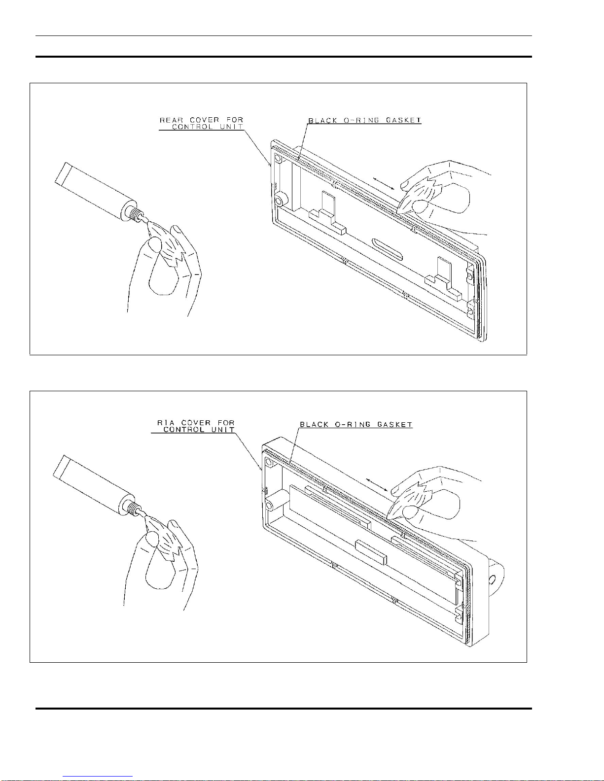
NOTE
For re-assembly of the Control Units (Front and Remote
Mounting) Revision "A" or later, be sure the black "ORing" is lubricated properly with "HIVAC-G" silicone
grease. (See Figures 1A and 1B for intructions.)
Steps:
1. Remove dust and dirt from the black O-Ring
gasket.
2 Apply proper amount of the silicone grease to cloth.
3. Put the silicone grease on throughout the surface of
the black O-Ring gasket evenly. (see Figures 1A
and 1B)
CAUTION
No fibers of the cloth must remain on the gasket after
silicone is applied
4. Wipe out protruded silicone grease from the
Rear/RIA Cover.
5
L
BI-38993
6
Figure 1A - Front Mount Control Unit "O-Ring" Lubrication
Figure 1B - Remote Mount Control Unit "O-Ring" Lubrication

3
ALIGNMENT PROCEDURES
INTRODUCTION
All operations of this radio are controlled by an
embedded digital computer, which is programmed with a
personality unique to the customer. In order to align and
test the radio, it must be programmed with a specific test
personality, which will allow conventional operation on
certain test frequencies. Furthermore, certain commands,
known as Test Mode Commands, cause the radio to
perform specific test functions. These will be noted as
required in the following alignment and troubleshooting
instructions.
In order to program a n ORION personality, the
radio and control unit must first be connected to a
Personal Computer via a PC Programming Cable and
hardware Programming Interface TQ3370 in one of the
configurations shown in Figures 2 and 3. Accessories
may be connected to the appropriate Accessory Cable
19B802554P1-P4 as needed.
The PC must be equipped with the EGE PC
Programming Software Version 4.0 or later. It is
assumed in this manual that the Service Technician is
familiar with the operation of the PC Programming
Software Programs "EDACS3" and "MRKMAINT."
Consult the PC Programming Software manuals for
further details regarding this software.
LBI-3899
CAUTION
Before bench testing the radio, be sure of the output
voltage characteristics of your bench power supply.
To protect the transmitter power output transistors from
possible instant destruction, the following input voltages
must not be exceeded
Transmitter unkeyed: 16.5 Volts
Transmitter keyed 16.3 Volts
(50 ohms resistive load)
Transmitter keyed 14.0 Volts
(no load or non-resistive load):
These voltages are specified at the normal vehicle
battery terminals of the radio and take the voltage drop
of standard cables into account. The voltage limits
shown for a non-optimum load is for "worst case"
conditions. For antenna mismatches likely to be
encountered in practice, the actual limit will approach
the 16.3 Volt figure.
Routine transmitter tests should be performed at EIA
Standard Test Voltages (13.6 VDC for loads of 6 to 16
amperes; 13.4 VDC for loads of 16 to 36 amperes).
Input voltages must not exceed the limits shown, even
for transient peaks of short duration.
Many commonly used bench power supplies cannot
meet these requirements for load regulation and
transient voltage suppression. Bench supplies which
employ "brute force" regulation and filtering (such as
Lapp Model 73) may be usable when operated in
parallel with a 12 Volt automotive storage battery.
7

L
BI-38993
8
Figure 2 - ORION Programming Configurations (USA)
Figure 3 - ORION Programming Configurations (EURO)
 Loading...