

Page 1

Exhibit8Manual‐Confidential
Page 2

PRELIMINARY
Radio Description
Radio 2217, Radio 2218 and Radio 0208
DESCRIPTION
181/1551-LZA 701 6001-1-V1 Uen PC3
Page 3

PRELIMINARY
Copyright
© Ericsson AB 2015–2016. All rights reserved. No part of this document may be
reproduced in any form without the written permission of the copyright owner.
Disclaimer
The contents of this document are subject to revision without notice due to
continued progress in methodology, design and manufacturing. Ericsson shall
have no liability for any error or damage of any kind resulting from the use
of this document.
Trademark List
All trademarks mentioned herein are the property of their respective owners.
These are shown in the document Trademark Information.
181/1551-LZA 701 6001-1-V1 Uen PC3 | 2016-01-13
Page 4

PRELIMINARY
Contents
Contents
1 Introduction 1
1.1 Warranty Seal 1
2 Product Overview 3
2.1 Main Features 4
2.2 Optional Equipment 5
3 Technical Data 7
3.1 Technical Data Summary 7
3.2 Installation Recommendations 14
3.3 Space Requirements 15
3.4 Acoustic Noise 21
3.5 Environmental Characteristics 21
3.6 Power Characteristics 23
3.7 System Characteristics 24
4 Hardware Architecture 27
4.1 Radio Overview 27
4.2 Fan Unit (Optional) 28
4.3 Optical Indicators and Buttons 29
5 Connection Interfaces 31
5.1 Position A and B, Antenna Interface 33
5.2 Position C, Maintenance Button 33
5.3 Position D, Optical Indicators 34
5.4 Position
E and F, Interface for Optical Cable to Main Unit 34
5.5 Position
G,
0
48 V DC Power Supply Interface 34
5.6 Position
H, Grounding Interface 35
5.7 Position I, Ext Alarm Interface 36
5.8 Position J, ALD Ctrl Interface 36
5.9 Position K and L, TX Monitor Interface (Optional) 36
5.10 Optional Equipment Interfaces 36
6 Standards and Regulations, Radio 2217 37
6.1 Regulatory Approval 37
181/1551-LZA 701 6001-1-V1 Uen PC3 | 2016-01-13
Page 5

PRELIMINARY
Radio Description
6.2 Other Standards and Regulations 40
7 Standards and Regulations, Radio 2218 41
7.1 Regulatory Approval 41
7.2 Other Standards and Regulations 43
8 Standards and Regulations, Radio 0208 45
8.1 Regulatory Approval 45
8.2 Other Standards and Regulations 47
181/1551-LZA 701 6001-1-V1 Uen PC3 | 2016-01-13
Page 6

PRELIMINARY
Introduction
1 Introduction
This document describes Radio 2217, Radio 2218 and Radio 0208.
1.1 Warranty Seal
The unit is equipped with a warranty seal sticker.
Note: Seals that have been implemented by Ericsson shall not be broken or
removed, as it otherwise voids warranty.
1
181/1551-LZA 701 6001-1-V1 Uen PC3 | 2016-01-13
Page 7

PRELIMINARY
Radio Description
2 181/1551-LZA 701 6001-1-V1 Uen PC3 | 2016-01-13
Page 8

PRELIMINARY
Product Overview
2 Product Overview
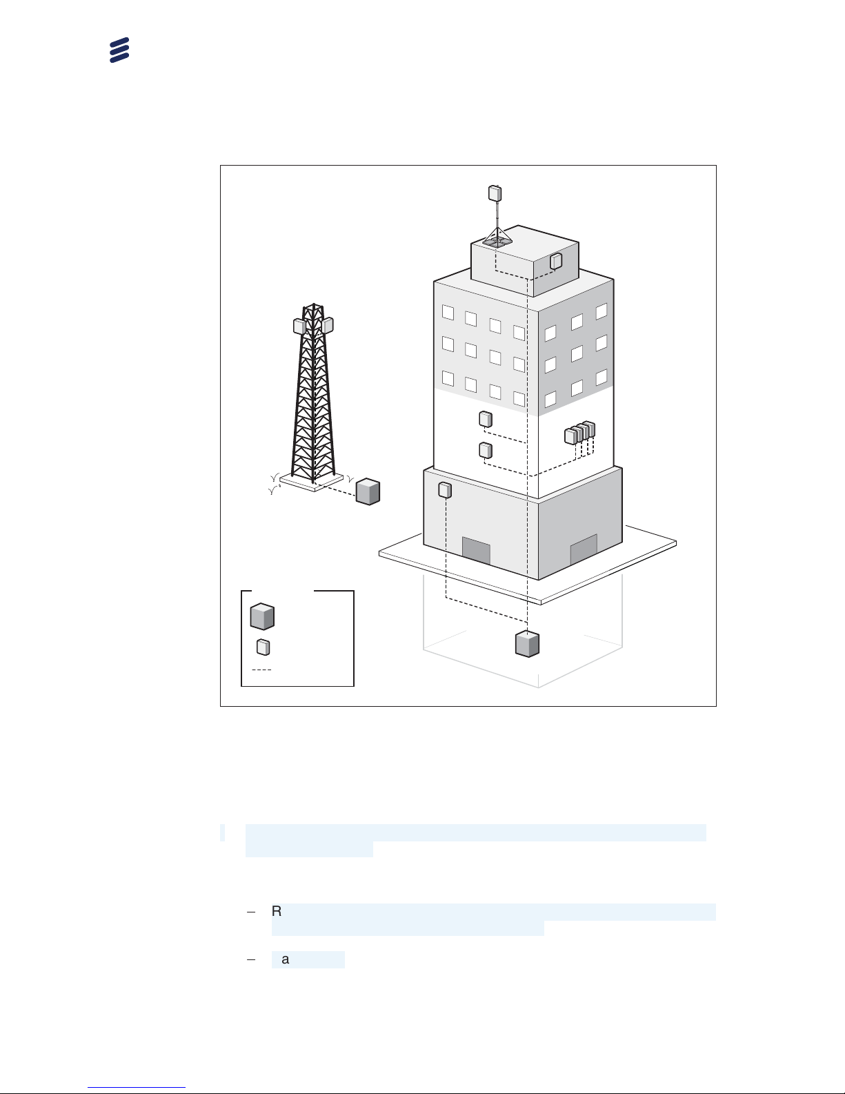
The radio remotely extends the reach of the Radio System, and is designed
to be located near the antenna. The radio is part of a modular radio building
concept that enables a variety of installation alternatives that are also easy to
expand. Flexible mounting solutions are provided using rails, pole clamps,
and brackets. The small size of the radio together with the flexible mounting
solutions reduces the site volume. The lower weight also improves the handling
of the radio.
An optic cable connects the radio to the Radio System main unit or an expanded
macro Radio System. The radios can be connected in a star configuration or
in a cascade configuration with optical cable links. An overview of different
radio installations is shown in Figure 1.
3
181/1551-LZA 701 6001-1-V1 Uen PC3 | 2016-01-13
Page 9
PRELIMINARY
Radio Description
Legends
Main unit
Ge7613B
Radio
Optical cable
Figure 1 Radio Installations
2.1 Main Features
The following are the main features of the radio:
• Supports 2- and 3-wire power connections. For 2-wire power solutions, a
DC adapter is used.
• Supports:
0
Radio 2217 and Radio 0208: Wideband Code Division Multiple Access
(WCDMA) and Long Term Evolution (LTE).
0
Radio 2218: LTE.
4
181/1551-LZA 701 6001-1-V1 Uen PC3 | 2016-01-13
Page 10

PRELIMINARY
Product Overview
• Supports:
0
Radio 2217 and Radio 0208: Frequency Division Duplex (FDD).
0
Radio 2218: Time Division Duplex (TDD).
• Supports:
0
Radio 2217 and Radio 2218: Duplex transmitter/receiver (2TX/2RX)
branches.
0
Radio 0208 has two uplink RX branches but no downlink TX branch. It
can be used as a two RX unit to add support for four way RX diversity
when used in combination with the following RRUs:
• RRUW 01/02
• RRUS 01
• RRUS 11
• RRUS 12
• RRUS 13
• Radio 2217
• Supports up to 9.8 Gbit/s CPRI (optical).
• Complies with 3GPP base station classes Medium Range (MR) and Wide
Area (WA); relevant standards are listed in
Section 6.1.4 on page 39
(Radio 2217), Section 7.1.4 on page 42 (Radio 2218) and Section 8.1.4
on page 46 (Radio 0208).
2.2 Optional Equipment
Optional equipment for Radio 2217 is the following:
• Fan unit.
5
181/1551-LZA 701 6001-1-V1 Uen PC3 | 2016-01-13
Page 11

PRELIMINARY
Radio Description
6 181/1551-LZA 701 6001-1-V1 Uen PC3 | 2016-01-13
Page 12

PRELIMINARY
Technical Data
3 Technical Data
This section contains the radio physical characteristics, environmental data,
and the power information of the Radio System.
3.1 Technical Data Summary
This section contains a technical data summary for Radio 2217, Radio 2218
and Radio 0208.
3.1.1 Radio 2217
The technical data for Radio 2217 is listed in
Table 1.
Table 1 Radio 2217 Technical Data
Description Value
Maximum nominal output
power
(1)(2)
2 x 10 W, 2 x 20 W, 2 x 30 W, and 2 x 40 W
(License key is required for total output power
over 20 W.)
Number of carriers WCDMA: One to eight carriers (B1); one to seven
carriers (B8); one to five carriers (B5)
LTE: One to three carriers
Mixed mode: Two to six carriers (B1); two to
seven carriers (B8); two to seven carriers (B5)
(HWAC required)
7181/1551-LZA 701 6001-1-V1 Uen PC3 | 2016-01-13
Page 13
PRELIMINARY
Radio Description
Description Value
1920–1980 MHz uplink
2110–2170 MHz downlink
B1 for WCDMA and LTE
1710–1785 MHz uplink
1805–1880 MHz downlink
B3 for LTE
880–915 MHz uplink
925–960 MHz downlink
B8 for WCDMA and LTE
832–862 MHz uplink
791–821 MHz downlink
B20 for LTE
718–748 MHz uplink
773–803 MHz downlink
B28A for LTE
Frequency
(3)
824–849 MHz uplink
869–894 MHz downlink
B5 for WCDMA and LTE
Dimensions without Fan Unit
Height
351 mm
Width
298 mm
Depth
127 mm
Dimensions with Fan Unit
Height
351 mm
Width
298 mm
Depth
138 mm
Weight without Fan
Radio 2217 B1, B3, B8,
B20, B28A
12.3 kg
Radio 2217 B5 13.3 kg
Weight with Fan
8 181/1551-LZA 701 6001-1-V1 Uen PC3 | 2016-01-13
Page 14
PRELIMINARY
Technical Data
Description Value
Radio 2217 B1, B3, B8,
B20, B28A
12.8 kg
Radio 2217 B5 13.8 kg
Color
Body NCS S 1002-B
Front NCS S 6502-B
(1) Detailed information about LTE licences can be found in License Management or
Manage Licenses.
(2) Detailed information about output power can be found in applicable Output Power User Guide.
(3) Information about Instantaneous Bandwidth (IBW) can be found in
RBS Configurations.
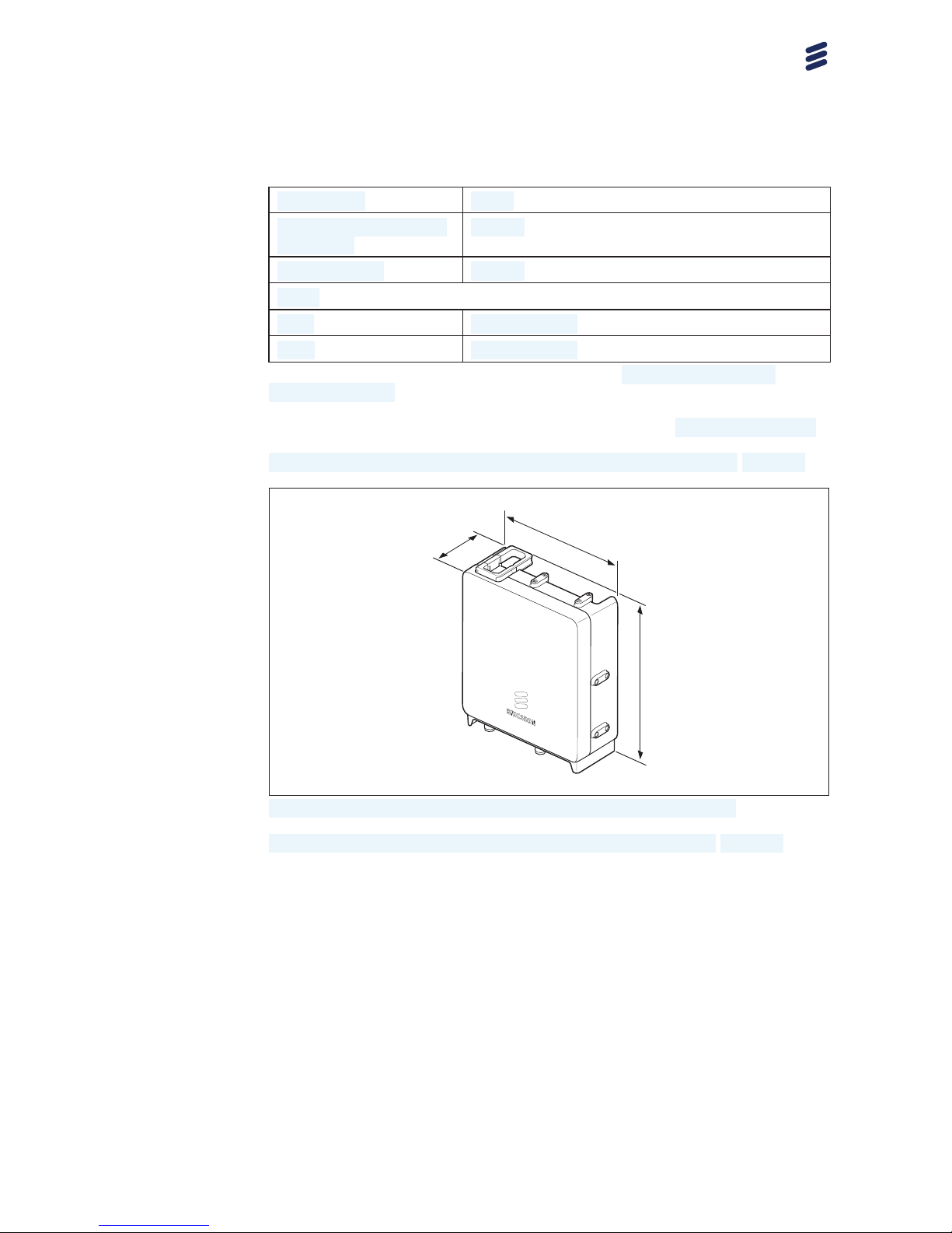
Radio 2217 height, width, and depth without fan unit, are shown in Figure 2.
Ge7599G
Unit of measurement: mm
351
127
298
Figure 2 Radio 2217 Height, Width, and Depth without Fan Unit
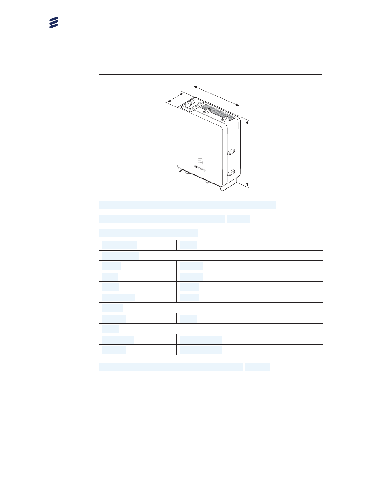
Radio 2217 height, width, and depth with fan unit, are shown in Figure 3
.
9
181/1551-LZA 701 6001-1-V1 Uen PC3 | 2016-01-13
Page 15
PRELIMINARY
Radio Description
Ge7606C
351
298
138
Unit of measurement: mm
Figure 3 Radio 2217 Height, Width, and Depth with Fan Unit
The technical data for the fan unit is listed in Table 2.
Table 2 Fan Unit Technical Data
Description Value
Dimensions
Height
351 mm
Width
298 mm
Depth
15 mm
Total depth
63 mm
Weight
Fan unit 0.5 kg
Color
Back cover
NCS S 1002-B
Fan box
NCS S 6502-B
The fan unit height, width, and depth, are shown in Figure 4.
10
181/1551-LZA 701 6001-1-V1 Uen PC3 | 2016-01-13
Page 16

PRELIMINARY
Technical Data
Ge7747C
351
298
63
15
Figure 4 Fan Unit Height, Width, and Depth
3.1.2 Radio 2218
The technical data for the radio is listed in
Table 3.
Table 3 Radio 2218 Technical Data
Description Value
Maximum nominal output
power
(1)(2)
2×10 W, 2×20 W, 2×30 W, and 2×40 W
(License key is required for total output power
over 20 W.)
Number of carriers LTE: One to three carriers
(HWAC required)
Frequency
(3)
1885–1915 MHz
B39A for LTE
Dimensions
Height
381mm
Width
291 mm
Depth
115 mm
Weight
Radio 2218 13.5 kg
11181/1551-LZA 701 6001-1-V1 Uen PC3 | 2016-01-13
Page 17

PRELIMINARY
Radio Description
Description Value
Color
Body NCS S 1002-B
Front NCS S 6502-B
(1) Detailed information about LTE licences can be found in License Management or
Manage Licenses.
(2) Detailed information about output power can be found in applicable Output Power User Guide.
(3) Information about Instantaneous Bandwidth (IBW) can be found in
RBS Configurations.
The radio height, width, and depth, are shown in
Figure 5.
Ge7599F
Unit of measurement: mm
381
115
291
Figure 5 Radio 2218 Height, Width, and Depth
3.1.3 Radio 0208
The technical data for Radio 0208 is listed in Table 4.
Table 4 Radio 0208 Technical Data
Description Value
Maximum nominal output
power
(1)(2)
N/A
(3)
Number of carriers WCDMA: One to eight carriers
LTE: One to three carriers
Mixed mode: One to eight carriers
(HWAC required)
12 181/1551-LZA 701 6001-1-V1 Uen PC3 | 2016-01-13
Page 18

PRELIMINARY
Technical Data
Description Value
Frequency
(4)
1920–1980 MHz uplink
B1 for WCDMA and LTE
Dimensions
Height
310 mm
Width
291 mm
Depth
63.4 mm
Weight
Radio 0208 8.4 kg
Color
Body NCS S 1002-B
Front NCS S 6502-B
(1) Detailed information about LTE licences can be found in License Management or
Manage Licenses.
(2) Detailed information about output power can be found in applicable
Output Power User Guide.
(3) The Radio 0208 is not TX-capable. When used in an RBB together with a TX-capable remote
radio, the output power of the RBB is that of the TX-capable remote radio.
(4) Information about Instantaneous Bandwidth (IBW) can be found in
RBS Configurations.
The radio height, width, and depth, are shown in Figure 6.
Ge7599G
Unit of measurement: mm
310
63.4
291
Figure 6 Radio 0208 Height, Width, and Depth
13
181/1551-LZA 701 6001-1-V1 Uen PC3 | 2016-01-13
Page 19

PRELIMINARY
Radio Description
3.2 Installation Recommendations
To achieve reliable operation, and maximum performance, an appropriate
installation location must be chosen.
3.2.1 Indoor Locations to Avoid
Although the unit is designed for outdoor use, it can also operate in an indoor
environment according to ETSI EN 300 019-1-3 class 3.1, 3.2, 3.3, and 3.6.
This does not cover installation with heat traps or installation in lofts, where
air ventilation does not exist. To ensure smooth performance of the product,
it is recommended to ensure that the planned installation site for the unit is
not a potential microclimate location. This typically occurs in places such as
unventilated lofts, sites with heat traps, or sites where the product is exposed to
direct sunlight through windows. Ensure proper ventilation and avoid installing
the equipment under glass covers or skylight windows.
3.2.2 Outdoor Locations to Avoid
Although Ericsson declares this product suitable for most outdoor environments,
this does not cover installations where the planned installation site for the unit
is a potential microclimate location. Typical examples for these microclimate
locations are sites where the products are not only exposed to the actual
temperature, but also additional temperature as heat coming from dark-colored
planes, for example, reflections from the floor or walls. The additional
temperature can generate heat traps with temperatures up to 10
C higher
than expected.
Avoid installing equipment in the following locations:
• Near the exhaust of building ventilation system.
• Near the exhaust of the chimney.
• Opposite large surfaces made of glass or new concrete.
3.2.3 Installations that Require Fan Unit
The Radio 2217 fan unit must be used in all installation scenarios where the
cables from the radio are not pointing directly downwards. The fan unit must
also be used in extreme conditions, such as installations with poor ventilation or
installations with heat traps.
3.2.4 Painting Limitations
Ericsson does not recommend painting the radio as it may affect radio
performance of the unit.
14
181/1551-LZA 701 6001-1-V1 Uen PC3 | 2016-01-13
Page 20

PRELIMINARY
Technical Data
Ericsson will apply limitations to the warranty and service contract if the radio is
painted.
3.2.4.1 Technical Limitations
If the radio is painted, be aware of the technical limitations below:
• Sunlight on dark paint may increase the temperature of the radio causing
it to shut down.
• The plastic surfaces and the plastic covers are suited for painting with
normal commercially available one or two component paints.
• Never use metallic paint or paint containing metallic particles.
• Ensure that ventilation and drainage holes are free from paint.
• Ensure proper adhesion of the paint.
3.2.4.2 Commercial Limitations
If the radio is painted, the commercial limitations below apply:
• Failure modes directly related to overheating due to painting are not valid
for repair within the scope of the warranty or standard service contract.
• Product failures related to paint contamination of components of the unit are
not valid for repair within the scope of warranty or standard service contract.
• When a painted unit is repaired, it will be restored to the standard color
before being returned to the market. It is not possible to guarantee the
same unit being sent back to the same place. This is also valid for units
repaired under a service contract.
• For repairs within the warranty period or a standard service contract, the
customer will be charged the additional costs for replacing all painted parts
of the unit or the complete unit.
3.3 Space Requirements
The installation alternatives for the radio are shown in Figure 7 and listed in
Table 5.
15
181/1551-LZA 701 6001-1-V1 Uen PC3 | 2016-01-13
Page 21

PRELIMINARY
Radio Description
C
B
A
D
Ge7629G
E
F
Figure 7 Installation Alternatives
16
181/1551-LZA 701 6001-1-V1 Uen PC3 | 2016-01-13
Page 22

PRELIMINARY
Technical Data
Table 5 Key to Installation Alternatives
Installation Method Description
A Wall installation
B Pole installation
(1)
C Wall installation with fan unit, only
Radio 2217
D Pole installation with fan unit, only
Radio 2217
(1)
E Wall installation without fan unit, only
Radio 0208
F Pole installation without fan unit, only
Radio 0208
(1)
(1) Maximum rail 450 mm
3.3.1 Generic Requirements
Parts of the radio can attain high temperatures during normal operation.
Therefore the radio must be installed in a classified service access area.
Exception applies when the radio is installed at a height that is not reachable
from ground level.
Allow a sufficient working space in front of the radio.
It is recommended that the radio is installed below, or behind the antenna. Do
not install the radio closer than 25 m from the main lobe of it its own antenna, or
antennas belonging to other services or operators using the same site.
3.3.2 Pole or Mast Installation
The installation requirements when installing the radio on a pole or a mast
are shown in Figure 8 .
17
181/1551-LZA 701 6001-1-V1 Uen PC3 | 2016-01-13
Page 23

PRELIMINARY
Radio Description
>200
Unit of measurement: mm
Top view Side view
>500
Antenna
Antenna
Radio
Radio
Radio
>200
Radio
>400
>300
Ge8998A
>7 >7
Figure 8 Radio Pole Installation Requirements
To ensure adequate airflow between the units, allow a minimum of 400 mm free
space between radios vertically installed on a horizontal rail on a single pole, or
a dual pole installation. Allow a minimum vertical distance of 500 mm between
radio and antenna, if installed above or below an antenna. The minimum
distance from the bottom of the radio to the floor is 300 mm.
Allow a minimum of 7 mm free space (created by the distance blocks) between
radios installed side by side on the rail.
For Radio 2217 and Radio 2218 allow for a minimum of 40 mm free space
between radios installed side by side on the rail when ambient temperature is
expected to be above +45C.
Note: A radio cannot be installed in the uppermost position of a pole or mast.
3.3.3 Rail Installation on Wall
This section describes the installation requirements when installing the radio
on a wall.
18
181/1551-LZA 701 6001-1-V1 Uen PC3 | 2016-01-13
Page 24

PRELIMINARY
Technical Data
3.3.3.1 Radio Installation on Outdoor Wall
The installation requirements if installing the radio outdoor on a wall are shown
in Figure 9.
Unit of measurement: mm
>400
>500
Ge8999A
Front View
>300
>7 >7
Antenna
>200
>500
Antenna
>500
Antenna
Figure 9 Radio Outdoor Wall Installation Requirements
To ensure adequate airflow between the units, allow a minimum of 400 mm
free space between radios vertically installed on a horizontal rail on a wall.
Allow a minimum vertical distance of 500 mm between radio and antenna, if
installed above or below an antenna. The minimum distance from the bottom
of the radio to the floor is 300 mm.
Allow a minimum of 7 mm free space (created by the distance blocks) between
radios installed side by side on the rail.
19
181/1551-LZA 701 6001-1-V1 Uen PC3 | 2016-01-13
Page 25

PRELIMINARY
Radio Description
For Radio 2217 and Radio 2218 allow for a minimum of 40 mm free space
between radios installed side by side on the rail when ambient temperature is
expected to be above +45C.
3.3.3.2 Radio Installation on Indoor Wall
The installation requirements if installing the radio on an indoor wall are shown
in Figure 10.
Unit of measurement: mm
>400
Ge9000A
Front View
>300
>300
>7>7
>1000
Top View
>7>7
Figure 10 Radio Indoor Wall Installation Requirements
To ensure adequate airflow between the units, allow a minimum of 400 mm free
space between radios vertically installed on a horizontal rail on a wall. The
minimum distance from the bottom of the radio to the floor is 300 mm.
Allow a minimum of 7 mm free space (created by the distance blocks) between
radios installed side by side on the rail.
For Radio 2217 and Radio 2218 allow for a minimum of 40 mm free space
between radios installed side by side on the rail when ambient temperature is
expected to be above +45C.
20
181/1551-LZA 701 6001-1-V1 Uen PC3 | 2016-01-13
Page 26

PRELIMINARY
Technical Data
3.4 Acoustic Noise
The radio may emit low levels of acoustic noise when operating on low capacity
in LTE.
With the Radio 2217 fan unit, the acoustic noise is ambient temperature
dependent.
The sound pressure level for Radio 2217 without fan and when operating on
low capacity in LTE can be 30 dBA.
The sound pressure levels for Radio 2217 with fan are shown in
Table 6.
Table 6 Sound Power Level
Temperature (C)
Sound Power Level (dBA)
> +25 44
+30 45
+40 49
+45 51
+55 55
The sound pressure level for Radio 2218 without fan and when operating on
low capacity in LTE can be 28 dBA.
3.5 Environmental Characteristics
This section contains operating environment data for the radio.
3.5.1 Operating Environment
The following are the values for the normal operating environment of the radio:
Temperature
(1)
0
40 to +55C
Solar radiation ≤ 1,120 W/m²
Relative humidity
5–100%
Absolute humidity 0.26–40 g/m
3
Maximum temperature change
1.0
C/min
Maximum wind load at 50 m/s (pole
installed single case)
260 N (front)
(1) Depending on installation scenario, traffic load, and configuration, the product might in the
highest 10
C temperature range, temporary reduce the output power. This depends on the
durations of the high ambient temperature.
21181/1551-LZA 701 6001-1-V1 Uen PC3 | 2016-01-13
Page 27

PRELIMINARY
Radio Description
3.5.2 Heat Dissipation
The radio is convection cooled and designed for outdoor installation. Table 7
shows the radio output power and maximum heat dissipation. Indoor installation
in a room without adequate ventilation and cooling must be avoided.
Table 7 Radio Heat Dissipation
Unit
Output Power (W)
Maximum Heat
Dissipation (kW)
Radio 2217 B1
2x40 0.22
Radio 2217 B3
2x40 0.22
Radio 2217 B8
2x40 0.22
Radio 2217 B20
2x40 0.25
Radio 2217 B28A
2x40 0.25
Radio 2217 B5
2x40 0.32
Radio 2218 B39A
2x40
0.27
Radio 0208 B1 N/A
0.036
3.5.3 Vibration
This section describes the radio tolerance to vibrations. The radio operates
reliably during seismic activity as specified by test method IEC 60068-2-57 Ff.
Maximum level of Required Response
Spectrum (RRS)
50 m/s
2
within 2–5 Hz for DR=2%
Frequency range 1–35 Hz
Time history signal Verteq II
The radio operates reliably during random vibration as specified by test method
IEC 60068-2-64 Fh
Random vibration, normal operation 0.3 m
2/s3
3.5.4 Materials
This section contains information about materials.
All Ericsson products fulfill the legal and market requirements regarding the
following:
• Material declaration
22
181/1551-LZA 701 6001-1-V1 Uen PC3 | 2016-01-13
Page 28

PRELIMINARY
Technical Data
• Materials' fire resistance, components, wires, and cables
• Recycling
• Restricted and banned material use
3.6 Power Characteristics
This section describes the power supply requirements, power consumption,
and fuse and circuit breaker recommendations for the radio.
Different power systems can supply power for multiple radios, if necessary.
3.6.1 DC Power Characteristics
The power supply voltage for the radio is048 V DC. The power supply
requirements are shown in Table 8.
Table 8 Radio DC Power Supply Requirements
Conditions
Values and Ranges
Nominal voltage
0
48 V DC
Operating voltage range Radio 2217 and Radio 0208:036.0 to058.5
VDC
Radio 2218:038.0 to058.5 V DC
Non-destructive range 0 to060 V DC
The radio is designed for 3-wire power connections. For 2-wire power solutions,
a DC adapter is used.
Fuse and Circuit Breaker Recommendations
The external fuse and circuit breaker recommendation for the radio are shown
in Table 9.
The recommendations given in this section are based on peak power
consumption and give no information on power consumption during normal
operation.
The recommended melting fuse type is gG-gL-gD in accordance with
IEC 60269-1. Circuit breakers must comply with at least Curve 3 tripping
characteristics, in accordance with IEC 60934.
The radio has a built-in Class 1 (Type 1) Surge Protection Device (SPD)
to protect the equipment in case of lightning and network transients. The
recommended fuse or circuit breaker rating is therefore dimensioned not to trip
the fuse or circuit breaker in case of most SPD operation. The minimum fuse
23
181/1551-LZA 701 6001-1-V1 Uen PC3 | 2016-01-13
Page 29

PRELIMINARY
Radio Description
rating could be taken into account only if it is accepted that fuses or circuit
breakers trip in such situations.
Table 9 External Radio Fuse and Circuit Breaker Recommendations
Unit (DC
Powered)
Output Power
(W)
Minimum Fuse
Rating
(1)
(A)
Fuse Rating
Recommended
for Reliable
Operation
(2)
(A)
Maximum
Allowed Fuse
Rating
(3)
(A)
Radio 2217 B1,
B3, B8, B20, B28A
and B5
2 x 40 W 16 A
25 A 32 A
Radio 2218 B39A 2 x 40 W 16 A 25 A 32 A
Radio 0208 B1 N/A 2A 2A
3A
Radio 2217 B1 +
Radio 0208 B1
2 x 40 W
16 A 25 A 32 A
(1) These fuse ratings can only be used if it is acceptable that fuses trip because of lightning or
network transients.
(2) The recommended fuse rating takes into account that external fuses are not to trip because
of lightning or network transients.
(3) The absolute maximum fuse class in accordance with radio design restrictions.
Note: If a fuse or circuit breaker rating above minimum fuse rating is
selected, cable dimensioning rules in Section 5.5 on page 34 are to
be reconsidered to make sure that the fuse or circuit breaker tripping
criteria are met.
3.6.2 AC Power Characteristics
The radio installation accepts 100–250 V AC when used together with an
optional PSU. For more information about the PSU, refer to PSU Description.
3.6.3 Power Consumption
For information about power consumption, refer to Power Consumption
Guideline for RBS 6000.
3.7 System Characteristics
This section describes the system characteristics of the Radio System.
3.7.1 RF Electromagnetic Exposure
General information on RF Electromagnetic Fields (EMF) for radios connected
to a Radio System from the 6000 family can be found in Radio Frequency
Electromagnetic Fields.
24
181/1551-LZA 701 6001-1-V1 Uen PC3 | 2016-01-13
Page 30

PRELIMINARY
Technical Data
Information about radio access specific compliance boundaries for
electromagnetic exposure can be found in Radio Frequency Electromagnetic
Exposure.
3.7.2 Software
Information on software dependencies can be found in Compatibilities for
Hardware and Software.
3.7.3 Radio Configurations
For information about available radio configurations, refer to RBS
Configurations.
25
181/1551-LZA 701 6001-1-V1 Uen PC3 | 2016-01-13
Page 31

PRELIMINARY
Radio Description
26 181/1551-LZA 701 6001-1-V1 Uen PC3 | 2016-01-13
Page 32

PRELIMINARY
Hardware Architecture
4 Hardware Architecture
This section describes the radio hardware structure regardless of configuration
or frequency. The
DC adapter, radio components and Y-power cable are
shown in
Figure 11 and listed in Table 10.
For a description of the supported radio configurations, refer to RBS
Configurations.
Ge7598H
A
C
B
D
Figure 11 DC Adapter, Radio Components and Y-Power Cable
Table 10 Key to DC Adapter and Radio Components
Position
Component
A DC adapter for 2-wire connector
B Radio
C Radio 2217 Fan unit
D Radio 0208 Y-power cable
4.1 Radio Overview
The radio contains most of the radio processing hardware. The following
sections describe the components inside the radio.
4.1.1 TRX
The Transmitter and Receiver (TRX) provides the following:
• Analog/Digital (A/D), Digital/Analog (D/A) conversion
27
181/1551-LZA 701 6001-1-V1 Uen PC3 | 2016-01-13
Page 33

PRELIMINARY
Radio Description
• Channel filtering
• Delay and gain adjustment
• Digital predistortion
• RF modulation and demodulation
• Optical cable interface termination
•
Two receivers for RX diversity
• RET modem (the antenna system communication link)
4.1.2 PA
The Multi Carrier Power Amplifier (MCPA) is the linear power amplifier for the
RF carriers. The radio has
two MCPAs, one for each branch.
4.1.3 FU
The Filter Unit (FU) consists of
low-noise amplifiers (only Radio 2217) and
band-pass filters.
In the radio, the FU also provides the following:
• Power and supervision for the TMA, or the RIU
• Voltage Standing Wave Ratio (VSWR) supervision
4.1.4 DC SPD
The DC SPD board protects the DC power input from lightning currents.
4.1.5 ALD (RET) SPD
An SPD provides overvoltage or overcurrent protection for the ALD (RET) port.
4.1.6 External Alarm SPD
An SPD provides overvoltage or overcurrent protection for the external alarm
ports.
4.2 Fan Unit (Optional)
The Radio 2217 fan is DC-powered (24 V DC) and controlled via the radio
external alarm port.
28
181/1551-LZA 701 6001-1-V1 Uen PC3 | 2016-01-13
Page 34

PRELIMINARY
Hardware Architecture
4.3 Optical Indicators and Buttons
The radio is equipped with optical indicators that show system status. The radio
optical indicators are located under the maintenance cover. The radio optical
indicators are shown in
Figure 12 and Figure 13 for Radio 0208, and explained
in Table 11.
The Radio 2217 fan unit optical indicators are located under a
cover and are shown in Figure 14, and explained in Table 12.
12
Ge7618C
12
B
C
D
E
A
Figure 12 Radio Optical Indicators and Buttons
12
Ge7618D
B
C
D
E
A
12
Figure 13 Radio Optical Indicators and Buttons for Radio 0208
Table 11 Description of Radio Optical Indicators and Buttons
Position Name Marking
A Maintenance button
–
29181/1551-LZA 701 6001-1-V1 Uen PC3 | 2016-01-13
Page 35

PRELIMINARY
Radio Description
Position Name Marking
B Fault
C Operational
D Maintenance
E Interface 1
Interface 2
Ge7619C
A
B
Figure 14 Radio 2217 Fan Unit Optical Indicators
Table 12 Description of Fan Unit Optical Indicators
Position Name Marking
A Fault
B Operational
For more information about the behavior of the optical indicators and the
maintenance button, refer to Indicators, Buttons, and Switches.
30
181/1551-LZA 701 6001-1-V1 Uen PC3 | 2016-01-13
Page 36

PRELIMINARY
Connection Interfaces
5 Connection Interfaces
This section contains information about the radio and fan unit connection
interfaces. The radio connection interfaces are shown in
Figure 15 and
Figure 16 for Radio 0208, and listed in Table 13, and the Radio 2217 fan unit
connection interface is shown in Figure 17 and listed in Table 14.
Ge7610E
12
L
C
B
K
A
D
G
H
F
E
J
I
Figure 15 Radio Connection Interfaces
Ge7610F
12
C
B
A
D
G
H
F
E
Figure 16 Radio 0208 Connection Interfaces
Table 13 Radio Connection Interfaces
Position Description Marking
Connector Types Cable Types
A Antenna A
B Antenna B
4.3-10 connector
C Maintenance button
– – –
31181/1551-LZA 701 6001-1-V1 Uen PC3 | 2016-01-13
Page 37

PRELIMINARY
Radio Description
Position Description Marking
Connector Types Cable Types
D Optical indicators
, ,
1,
2
– –
E Optical cable 1
1
F Optical cable 2
2
LC (On SFP)
G
0
48 V DC power supply POWER Screw terminal
connector
H Grounding 2 x M6 bolt
I External alarm and fan unit
power supply and control
Mini-DIN connector,
14 pin
J ALD (used for a RET unit
for example)
ALD Mini-DIN connector, 8
pin
K
(1)
TX monitor A
L
(1)
TX monitor B
SMA connector
(1) Radio 2217: Optional for Radio 2217 B1, B3, B8, B20, B28A and B5. Radio 2218: The TX monitor interface is not
hardware ready, function is not applicable.
32 181/1551-LZA 701 6001-1-V1 Uen PC3 | 2016-01-13
Page 38

PRELIMINARY
Connection Interfaces
Ge7791A
A
Figure 17 Radio 2217 Fan Unit Connection Interface
Table 14 Description of Radio 2217 Fan Unit Connection Interface
Position Description Marking
A External alarm
5.1 Position A and B, Antenna Interface
The antenna interfaces provide connections for the radio to antennas. RF
cables connect the radio to the antenna.
The antenna connection interface characteristics of these cables are described
in Table 15.
Table 15 Radio Antenna Connection Interface Characteristics
Connector Type RF Cable Type Cable Connector Type
4.3-10, insert-receiver type 50coaxial
4.3-10 type
Table 16 shows how to connect the antenna cables.
Table 16 Radio Antenna Cable Connectors
Radio Connectors Antenna Connectors
(Antenna A)
TX/RX
(1)
(Antenna B)
TX/RX
(1)
(1) Radio 0208 only has RX branches.
5.2 Position C, Maintenance Button
The maintenance button is at the left of the symbol.
33
181/1551-LZA 701 6001-1-V1 Uen PC3 | 2016-01-13
Page 39

PRELIMINARY
Radio Description
More information about the maintenance button can be found in Indicators,
Buttons, and Switches.
5.3 Position D, Optical Indicators
Optical indicators show the system status. More information about the optical
indicators can be found in Indicators, Buttons, and Switches.
5.4 Position E and F, Interface for Optical Cable to Main
Unit
The 1 and 2 interfaces provide connections to optical cables for traffic
and timing signals between the radio and the main unit. A Small Form-factor
Pluggable (SFP)+ is used to connect the optical cable to the radio.
Note: The radio uses SFP+ modules for optical transmission and optical radio
interfaces on Data 1 (optical cable 1 in) and Data 2 (optical cable 2 out).
Only use SFP+ modules approved and supplied by Ericsson. These modules
fulfill the following:
• Compliance with Class 1 laser product safety requirements defined in
standard IEC 60825-1.
• Certification according to general safety requirements defined in standard
IEC 60950-1.
• Functional and performance verified to comply with Radio System
specifications.
Recommended SFP+ modules are obtained from the product packages for the
Radio System and the Main Remote Installation products. For more information
about SFP modules, refer to Spare Parts Catalog and Main-Remote Installation
Products Overview for more information.
5.5 Position G,048 V DC Power Supply Interface
The048 V DC power connection is made through a connector. The connector
accepts cables with various cross-sectional areas depending on the cable
length and the radio consumption. The values can be found in Figure 18, and
are calculated using the following formulas:
R=2×(0.02/D)
R- cable resistance
D- cable area (mm
2
)
34
181/1551-LZA 701 6001-1-V1 Uen PC3 | 2016-01-13
Page 40

PRELIMINARY
Connection Interfaces
L=4V/(R×i)
L- the maximum permitted distribution length
R- calculated cable resistance
i- current which
Radio 2217 uses at 36V or Radio 2218 uses at 38V
Ge3616B
Radio power consumption [W]
Cable length [m]
Figure 18 Maximum Cable Lengths versus Radio Power Consumption (4V@36V/38V)
The power cable conductor has a wire for the 0 V conductor and a wire for the
0
48 V conductor. The wire color code for both is market dependent.
All cables must be shielded. The shielding must be properly connected both
to the power connector and to the earthing interface in the power supply
equipment, otherwise the radio overvoltage and lightning protection does not
function properly.
5.6 Position H, Grounding Interface
The radio must be earthed to protect it from overvoltage and lightning strikes.
The grounding interface on the radio accepts an M6 dual cable lug on a coated
cable.
For more information about grounding principles, refer to Grounding Guidelines
for RBS Sites.
35
181/1551-LZA 701 6001-1-V1 Uen PC3 | 2016-01-13
Page 41

PRELIMINARY
Radio Description
5.7 Position I, Ext Alarm Interface
Two external alarms can be connected to the radio external alarm port.
5.8 Position J, ALD Ctrl Interface
The ALD control (ALD Ctrl) connects an ALD (RET) cable to the radio for
antenna system communication.
5.9 Position K and L, TX Monitor Interface (Optional)
Note: This section only applies to Radio 2217.
The TX monitor interfaces provide the monitoring for the output power and
are shown in Table 17.
Table 17 TX Monitor Cable Connectors
Radio Connectors
TX Monitor Connectors
TX Monitor A SMA Connector
TX Monitor B SMA Connector
5.10 Optional Equipment Interfaces
The equipment presented in this section is optional and can be ordered
separately.
5.10.1 Fan Unit
The Radio 2217 fan unit consists of a replaceable fan tray with three fans.
36
181/1551-LZA 701 6001-1-V1 Uen PC3 | 2016-01-13
Page 42

PRELIMINARY
Standards and Regulations, Radio 2217
6 Standards and Regulations, Radio 2217
This section presents a brief overview of standards, regulatory product
approval, and declaration of conformity for Radio 2217.
Declaration of Conformity
"Hereby, Ericsson AB, declares that this RBS is in compliance with the
essential requirements and other relevant provisions of Directive 1999/5/EC
and 2011/65/EU."
6.1 Regulatory Approval
The Radio System complies with the following market requirements:
• European Community (EC) market requirements, R&TTE Directive
1999/5/EC
0168
Alert Mark (Class 2 equipment). Restrictions to use the
apparatus may apply in some countries or geographic areas. Individual
license to use the specific radio equipment may be required.
The apparatus may include radio Transceivers with support for frequency
bands not allowed or not harmonized within the EC.
• Restriction of Hazardous Substances in Electrical and Electronic Equipment
(RoHS) Directive (2011/65/EU).
• Products containing radio Equipment outside North America and in
countries not recognizing the CE-mark may be labeled according to national
requirements or standards.
• Japanese market requirements
6.1.1 Environmental Standards Compliance
The Radio System complies with the following environmental standard:
Europe
•
EN 50 581 (RoHS)
37
181/1551-LZA 701 6001-1-V1 Uen PC3 | 2016-01-13
Page 43

PRELIMINARY
Radio Description
6.1.2 Safety Standards Compliance
In accordance with market requirements, the Radio System complies with the
following product safety standards and directives:
International
• IEC 60215
• IEC 60950-1
Europe
• EN 50 385
• EN 60 215
• EN 60 950-1
6.1.2.1 Outdoor Specific Requirements
The Radio System complies with the following outdoor specific requirements:
International
• IEC 60529 (IP65)
• IEC 60950-22
Europe
• EN 60 529 (IP65)
• EN 60 950-22
6.1.3 EMC Standards Compliance
The Radio System complies with the following Electromagnetic Compatibility
(EMC) standards:
International
• 3GPP TS25.113
• 3GPP TS36.113
• 3GPP TS37.113
38
181/1551-LZA 701 6001-1-V1 Uen PC3 | 2016-01-13
Page 44

PRELIMINARY
Standards and Regulations, Radio 2217
Europe
• ETSI EN 301 489-1
• ETSI EN 301 489-23
• ETSI EN 301 489-50
6.1.4 Radio Standards Compliance
The Radio System complies with the following radio standards:
International
•
3GPP TS25.141
• 3GPP TS36.141
• 3GPP TS37.141
Europe
• ETSI EN 301 502
• ETSI EN 301 908-1
• ETSI EN 301 908-3
• ETSI EN 301 908-14
• ETSI EN 301 908-18
Japan
• TELEC-T112
• TELEC-T146
6.1.5 Marking
To show compliance with legal requirements, the product is marked with the
following labels:
Europe
• CE mark
39
181/1551-LZA 701 6001-1-V1 Uen PC3 | 2016-01-13
Page 45

PRELIMINARY
Radio Description
6.2 Other Standards and Regulations
The standards and regulations in this section are not regulatory requirements.
6.2.1 Spare Parts
This radio complies with the Ericsson Serviceability and Spare Parts Strategy.
6.2.2 Surface Quality
The surface quality of the radio is in accordance with Ericsson standard class
A3.
6.2.3 Vandal Resistance
Unauthorized access is not possible without damaging the unit.
40
181/1551-LZA 701 6001-1-V1 Uen PC3 | 2016-01-13
Page 46

PRELIMINARY
Standards and Regulations, Radio 2218
7 Standards and Regulations, Radio 2218
This section presents a brief overview of standards, regulatory product
approval, and declaration of conformity.
Declaration of Conformity
"Hereby, Ericsson AB, declares that this RBS is in compliance with the
essential requirements and other relevant provisions of Directive 1999/5/EC
and 2011/65/EU."
7.1 Regulatory Approval
The Radio System complies with the following market requirements:
• European Community (EC) market requirements, R&TTE Directive
1999/5/EC
0168
Alert Mark (Class 2 equipment). Restrictions to use the
apparatus may apply in some countries or geographic areas. Individual
license to use the specific radio equipment may be required.
The apparatus may include radio Transceivers with support for frequency
bands not allowed or not harmonized within the EC.
• Restriction of Hazardous Substances in Electrical and Electronic Equipment
(RoHS) Directive (2011/65/EU).
• Products containing radio Equipment outside North America and in
countries not recognizing the CE-mark may be labeled according to national
requirements or standards.
7.1.1 Environmental Standards Compliance
The Radio System complies with the following environmental standard:
Europe
• EN 50 581 (RoHS)
7.1.2 Safety Standards Compliance
In accordance with market requirements, the Radio System complies with the
following product safety standards and directives:
41
181/1551-LZA 701 6001-1-V1 Uen PC3 | 2016-01-13
Page 47

PRELIMINARY
Radio Description
International
• IEC 60215
• IEC 60950-1
Europe
• EN 50 385
• EN 60 215
• EN 60 950-1
7.1.2.1 Outdoor Specific Requirements
The Radio System complies with the following outdoor specific requirements:
International
• IEC 60529 (IP65)
• IEC 60950-22
Europe
• EN 60 529 (IP65)
• EN 60 950-22
7.1.3 EMC Standards Compliance
The Radio System complies with the following Electromagnetic Compatibility
(EMC) standards:
International
• 3GPP TS36.113
• 3GPP TS37.113
Europe
• ETSI EN 301 489-1
• ETSI EN 301 489-23
• ETSI EN 301 489-50
42
181/1551-LZA 701 6001-1-V1 Uen PC3 | 2016-01-13
Page 48

PRELIMINARY
Standards and Regulations, Radio 2218
7.1.4 Radio Standards Compliance
The Radio System complies with the following radio standards:
International
• 3GPP TS36.141
• 3GPP TS37.141
Europe
• ETSI EN 301 908-1
• ETSI EN 301 908-14
• ETSI EN 301 908-18
7.1.5 Marking
To show compliance with legal requirements, the product is marked with the
following labels:
Europe
• CE mark
7.2 Other Standards and Regulations
The standards and regulations in this section are not regulatory requirements.
7.2.1 Spare Parts
This radio complies with the Ericsson Serviceability and Spare Parts Strategy.
7.2.2 Surface Quality
The surface quality of the radio is in accordance with Ericsson standard class
A3.
7.2.3 Vandal Resistance
Unauthorized access is not possible without damaging the unit.
43
181/1551-LZA 701 6001-1-V1 Uen PC3 | 2016-01-13
Page 49

PRELIMINARY
Radio Description
44 181/1551-LZA 701 6001-1-V1 Uen PC3 | 2016-01-13
Page 50

PRELIMINARY
Standards and Regulations, Radio 0208
8 Standards and Regulations, Radio 0208
This section presents a brief overview of standards, regulatory product
approval, and declaration of conformity for Radio 0208.
Declaration of Conformity
"Hereby, Ericsson AB, declares that this RBS is in compliance with the
essential requirements and other relevant provisions of Directive 1999/5/EC
and 2011/65/EU."
8.1 Regulatory Approval
The Radio System complies with the following market requirements:
• European Community (EC) market requirements, R&TTE Directive
1999/5/EC
0168
Alert Mark (Class 2 equipment). Restrictions to use the
apparatus may apply in some countries or geographic areas. Individual
license to use the specific radio equipment may be required.
The apparatus may include radio Transceivers with support for frequency
bands not allowed or not harmonized within the EC.
• Restriction of Hazardous Substances in Electrical and Electronic Equipment
(RoHS) Directive (2011/65/EU).
• Products containing radio Equipment outside North America and in
countries not recognizing the CE-mark may be labeled according to national
requirements or standards.
8.1.1 Environmental Standards Compliance
The Radio System complies with the following environmental standard:
Europe
• EN 50 581 (RoHS)
8.1.2 Safety Standards Compliance
In accordance with market requirements, the Radio System complies with the
following product safety standards and directives:
45
181/1551-LZA 701 6001-1-V1 Uen PC3 | 2016-01-13
Page 51

PRELIMINARY
Radio Description
International
• IEC 60950-1
Europe
• EN 50 385
• EN 60 950-1
8.1.2.1 Outdoor Specific Requirements
The Radio System complies with the following outdoor specific requirements:
International
• IEC 60529 (IP65)
• IEC 60950-22
Europe
• EN 60 529 (IP65)
• EN 60 950-22
8.1.3 EMC Standards Compliance
The Radio System complies with the following Electromagnetic Compatibility
(EMC) standards:
International
• 3GPP TS25.113
• 3GPP TS36.113
• 3GPP TS37.113
Europe
• ETSI EN 301 489-1
• ETSI EN 301 489-23
• ETSI EN 301 489-50
46
181/1551-LZA 701 6001-1-V1 Uen PC3 | 2016-01-13
Page 52

PRELIMINARY
Standards and Regulations, Radio 0208
8.1.4 Radio Standards Compliance
The Radio System complies with the following radio standards:
International
• 3GPP TS25.141
• 3GPP TS36.141
• 3GPP TS37.141
Europe
• ETSI EN 301 908-1
• ETSI EN 301 908-3
• ETSI EN 301 908-14
• ETSI EN 301 908-18
8.1.5 Marking
To show compliance with legal requirements, the product is marked with the
following labels:
Europe
• CE mark
8.2 Other Standards and Regulations
The standards and regulations in this section are not regulatory approved.
8.2.1 Spare Parts
This radio complies with the Ericsson Serviceability and Spare Parts Strategy.
8.2.2 Surface Quality
The surface quality of the radio is in accordance with Ericsson standard class
A3.
47
181/1551-LZA 701 6001-1-V1 Uen PC3 | 2016-01-13
Page 53

PRELIMINARY
Radio Description
8.2.3 Vandal Resistance
Unauthorized access is not possible without damaging the unit.
48
181/1551-LZA 701 6001-1-V1 Uen PC3 | 2016-01-13
 Loading...