

Page 1

Mobile Communications
LBI-38838A
DUAL FORMAT MDR
TM
MOBILE RADIO
Operator's Manual
Page 2

TABLE OF CONTENTS
Page
SAFETY INFORMATION.................................................................. 5
SAFE DRIVING RECOMMENDATIONS FOR USERS OF MOBILE
RADIOS.................................................................................... 6
OPERATING PROCEDURES............................................................. 6
INTRODUCTION ............................................................................... 7
USER INTERFACE............................................................................. 8
BUTTONS ................................................................................ 9
KEYPAD .................................................................................. 11
Function Portion.......................................................... 11
Numeric Portion........................................................... 11
Extended Features........................................................ 12
DISPLAY.................................................................................. 13
Messages...................................................................... 14
Status Indicators .......................................................... 14
ALERT TONES................................................................................... 15
EDACS APPLICATIONS ......................................................... 15
GE-MARC APPLICATIONS .................................................... 16
OPERATION....................................................................................... 17
GENERAL................................................................................ 17
Removing and Replacing Handset................................ 17
Turning The Radio ON/OFF........................................ 17
Volume Adjust............................................................. 17
EDACS OPERATION............................................................... 17
System/Area Selection-Ramping Names*..................... 18
System/Area Selection-Direct Number Entry*.............. 18
Group Selection-Ramping Names*............................... 18
Group Selection-Direct Number Entry*........................ 18
Unlocking The Radio*................................................. 19
Locking The Radio*..................................................... 19
Backlight* ................................................................... 19
Programmable Flex Keys* ........................................... 19
*Indicates EDACS And GEMARC Applications
Copyright November 1993, Ericsson GE Mobile Communications Inc.
2
Page 3

TABLE OF CONTENTS (CONTINUED)
Page
Interconnect Dialing .................................................... 19
REDIAL Key* ............................................................. 19
Individual Call Dialing................................................ 19
Individual Call Notification.......................................... 20
Storing An Individual Call ID...................................... 20
Using Special Call Lists*............................................. 20
Storing A Telephone Number To The Call List*.......... 21
Recalling calls from the call list* ................................. 21
Simplex Operation*..................................................... 21
*/System Key usage ..................................................... 21
END key Usage............................................................ 21
Last Digit Clear And Display Clear*............................ 22
1/HORN Key*.............................................................. 22
4/EXT SPK*................................................................ 22
5/SIMPLX ................................................................... 22
6/MUTE*..................................................................... 23
8/SCAN....................................................................... 23
9/SCAN ADD.............................................................. 23
0/SPC .......................................................................... 23
A/Testmode ................................................................. 23
B/Pause........................................................................ 23
C/Call Timer*.............................................................. 24
PROGRAMMABLE OPTIONS................................................. 24
Call Time-outs............................................................. 24
Emergency................................................................... 24
Automatic Login.......................................................... 25
Wide Area System Scan............................................... 25
Supervisory Mode........................................................ 25
Programmable Audio/Display ...................................... 25
Priority System Scan.................................................... 25
Group Options ............................................................. 25
TX Disable-Group Option............................................ 25
Rx Disable-Group Option............................................. 26
Control Channel Limits ............................................... 26
Conventional Failsoft Channel..................................... 26
GE-MARC OPERATION............................................ 26
Placing A Dispatch Call............................................... 26
Placing An Interconnect Or Dispatch Overdial Call..... 27
Storing A Dispatch Overdial Call................................. 27
3/OVERDIAL.............................................................. 27
3
Page 4

TABLE OF CONTENTS (CONTINUED)
Page
8/CNF CALL............................................................... 28
Ending A Call.............................................................. 28
Receiving A Call.......................................................... 28
CONVENTIONAL MODE OPERATION................................. 29
Direct Mode Operation (Optional)................................ 29
MAINTENANCE AND BASIC CARE................................................ 30
ANTENNA REMOVAL............................................................ 30
FUSE REPLACEMENT............................................................ 30
JUMP STARTING THE VEHICLE........................................... 30
CLEANING INSTRUCTIONS............................................................ 30
AVAILABLE OPTIONS ..................................................................... 31
FREQUENTLY CALLED NUMBERS................................................ 32
4
Page 5

SAFETY INFORMATION
The operator of any mobile radio should be aware of certain hazards
common to the operation of vehicular radio transmissions.
A list of possible hazards follows:
1. Explosive Atmospheres
Just as it is dangerous to fuel a vehicle with the motor running, be sure to
turn the radio off while fueling the vehicle. Do not carry containers of
fuel in the trunk of the vehicle when the radio is mounted in the trunk.
2. Interference to Vehicular Electronics Systems
Electronic fuel injection systems, electronic anti-skid braking systems,
etc., are typical of the type of electronic devices that may malfunction due
to the lack of protection from radio frequency energy present when
transmitting. If the vehicle contains such equipment, consult the dealer of
your vehicle and enlist his aid in determining if such electronic circuits
perform normally when the radio is transmitting.
3. Dynamite Blasting Caps
Dynamite blasting caps may be caused to explode by operating a radio
within 500 feet of the blasting caps. Always obey the "Turn Off Two
Way Radios" signs posted where dynamite is being used. When
transporting blasting caps in your vehicle:
a. Carry the blasting caps in a closed metal box with a soft lining.
b. Leave the radio OFF whenever the blasting caps are being put into
or removed from the vehicle.
4. Radio Frequency Energy
To prevent burns or related physical injury from radio frequency energy,
do not operate the transmitter when anyone outside of the vehicle is
within two feet of the antenna.
5. Liquefied (LP) Gas Powered Vehicles
Mobile radio installations i n vehicles powered by liquefied petroleum gas
with the LP gas container in the trunk or other sealed-off space within the
5
Page 6

interior of the vehicle must conform to the National Fire Protection
Association standard (NFPA) 58 requiring that:
a. The space containing the radio equipment shall be isolated by a seal
from the space containing the LP gas container and its fittings.
b. Outside filling connections shall be used for the LP gas container.
c. The LP gas container shall be vented to the outside of the vehicle.
SAFE DRIVING RECOMMENDATIONS FOR USERS OF MOBILE
RADIOS*
Read the literature on the safe operation of the radio.
Keep both hands on the steering wheel and the handset i n its cradle
whenever the vehicle is in motion.
Place calls only when vehicle is stopped. Use on-hook dialing and
recall dialing to speed the time it takes to call.
When talking from a moving vehicle is unavoidable, drive in the
slower lane. Keep conversations brief.
If conversation requires taking notes or complex thought, stop the
vehicle in a safe place and continue the call.
Whenever using a mobile radio exercise caution.
*As recommended by the AAA.
OPERATING PROCEDURES
Two-way FM radio systems must be operated in accordance with the rules
and regulations of the Federal Communications Commission (FCC). Operators
of two-way radio equipment must be thoroughly familiar with the rules that
apply to the intended type of radio operation. Following these rules helps to
eliminate confusion, assures the most efficient use of existing radio channels,
and results i n a smoothly functioning radio network. When using this two-way
radio remember these rules:
1. It is a violation of FCC rules to interrupt any distress or emergency
message. As the radio operates in much the same way as a telephone
6
Page 7

"party line", always listen to make sure that the line is clear - that no one
else is on the air - before sending messages. If someone is sending an
emergency message - such as reporting a fire, or asking for help in an
accident - KEEP OFF THE AIR! Emergency calls have priority over al l
other messages.
2. Use of profane or obscene language is prohibited by Federal law.
3. It is against the law to send false call letters, or a false distress or
emergency message.
4. The FCC requires that conversations be kept brief and confined to
business. To save time, use coded messages whenever possible.
5. Using a radio to send personal messages (except in an emergency) is a
violation of the FCC rules. Send only those messages that are essential for
business operation.
6. It is against Federal law to repeat or otherwise make known anything
overheard on the radio. Conversations between others sharing a channel
must be regarded as confidential.
7. The FCC requires the operator to transmit station identification at certain
times by means of call letters. Refer to the FCC rules for your station's
particular type of operation for the proper procedure.
NOTE
The GE-MARC and EDACS trunking environments have automatic
identification features built in and do not require the user to identify by
means of call letters.
8. No changes or adjustments shall be made to the equipment except by an
authorized or certified electronics technician.
INTRODUCTION
This manual describes how to use the Ericsson GE Dual Format MDR
Mobile Radio. The Dual Format MDR is a synthesized, microprocessor-based,
high performance duplex mobile FM radio providing reliable two-way
communications in both the GE-MARC and Enhanced Digital Access
Communications System (EDACS) trunking environments. The radio also
provides non-trunked operation for use with conventional communications
7
Page 8

systems. An optional talk-around kit provides direct mobile to mobile
communication when out of repeater range.
Duplex operation is provided in EDACS and GE-MARC systems while
operating in the Telephone Interconnect Mode. At all other times, the radio
provides simplex communications, i.e. when placing group calls in either the
EDACS or GE-MARC environments or when operating in the conventional
mode.
In an EDACS trunked environment the user selects a communications
system and group. In this mode, channel selection is transparent to the user and
is controlled via digital communication with the system controller. This
provides advanced programmable features and fast access to communication
channels.
In a GE-MARC trunked environment the user selects a communications
area and group. In this mode, channel selection is automatic and is controlled
via tone signalling.
In the conventional mode, the user selects a channel and directly
communicates on that channel. In this mode, a system refers to a set of
channels and a channel is a transmit/receive radio frequency pair.
The exact operation of the radio depends on the operating mode, the
radio's programming, and the particular radio system. Most features described
in this manual may be enabled or disabled through programming. Consult the
system administrator for the required features to be programmed into the radio.
USER INTERFACE
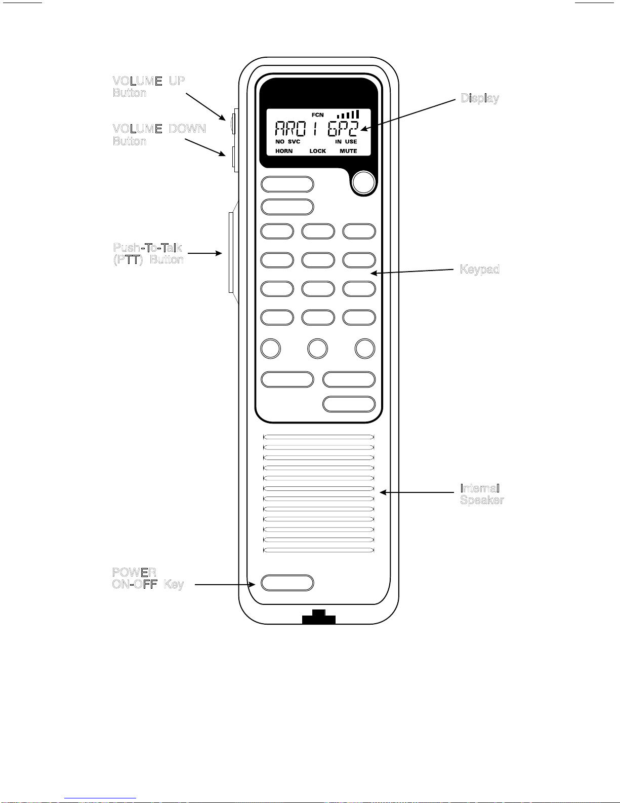
All of the Dual Format MDR operating controls are located on the radio's
handset. A 22-button keypad, an internal speaker and a liquid crystal display
(LCD) for radio status information are located on the top side of the handset for
convenience while the handset is secured in its holder. An earpiece and
microphone are positioned on the handset's bottom side as found on a basic
telephone. Viewed from the handset's top side, a VOLUME UP button,
VOLUME DOWN button and the Push-To-Talk (PTT) button are located on
the left side.
The keypad is used for manual number entry for individual calls, access to
a telephone interconnect system and activation of various EDACS, GE-MARC
or conventional features. The keypad is divided into both a function portion and
a numeric portion as is found on a basic push-button telephone.
8
Page 9

The display has an eight alphanumeric character line used to show the
operational mode of the radio. Eight status indicators, used to indicate various
operating conditions, such as; function key pressed, transmitter on, service no t
available, radio in use, horn alert active, radio locked or transmit muted, are
located above and below the character line within the display. A back light
function illuminates the display and keypad for nighttime use.
BUTTONS
This section describes the function of the three buttons on the side of the
handset.
VOLUME UP Increases the volume level. 15 is the maximum
BUTTON level.
VOLUME DOWN Decreases the volume level. 00 is the minimum
BUTTON level unless programmed otherwise.
NOTE
When the VOLUME UP or VOLUME DOWN button is pressed,
the volume setting can be momemtarily displayed on the handset LCD
(e.g., VOL=15) if the radio is not actively receiving a call and the function
is enabled through programming. If not programmed with a power up
volume level, the radio retains the last setting used when the radio was
powered off.
PUSH-TO-TALK Enables the radio's transmitter. PTT must be
(PTT) BUTTON held down to transmit during simplex operation.
9
Page 10
VOLUME UP
Button
VOLUME DOWN
Button
Display
Push-To-Talk
(PTT) Button
END
CLR
HORN
QZ
1
EXT SPK
GHI
4
LOCK
PRS
7
SYSTEM
SEND
BACKLIGHT
2
SIMPLEX
5
ABC
JKL
OVERDIAL
DEF
3
MUTE
MNO
6
Keypad
TUV
8
SPC
OPER
0
✱
WXY
9
GROUP
#
TALK TIME
B CA
FCNSTO
RCL
POWER
ON-OFF Key
Internal
Speaker
POWER
Figure 1 - Dual Format MDR Handset
10
Page 11

KEYPAD
Function Portion
END Terminates any ongoing activity. If the radio is designated as
supervisory, it drops any ongoing group call.
SEND Initiates a call by sending the number shown in the display or
functions as the PTT button if no number has been previously
entered.
CLR Clears the last digit entered when pressed and released. Press and
hold for at least one second to clear the entire number.
A, B, C Flex Keys that can be used in two ways: 1) quick dial frequently
called or emergency numbers or 2) extended functions such as
Special Calls, Public Address, Horn Alert, Emergency (EDACS), or
Home System/Group. Each "Flex Key" can store one number for a
total of three.
STO Stores numbers in memory locations.
FCN Activates extended features. The extended features are labeled above
each associated key on the keypad. FCN is pressed before the
associated key to enable the secondary function of that key.
RCL Recalls numbers from memory locations.
POWER Applies power to the radio. Press once to turn the radio on. All
status indicators turn on momentarily. Press a second time to turn
the radio off. When turned off, the radio retains the last user
selections (unless programmed for a particular power up option).
Numeric Portion
0 OPER-9 WXY Enters telephone numbers and activates extended features.
* Ramps through the system and area list and selects a
system or area.
DURING A CALL - sends the DTMF (Dual-Tone
Multi-Frequency) tone for *.
IN DISPATCH MODE - brings up the dial tone.
11
Page 12

# Ramps through the group and channel list and selects a
group or channel.
DURING A CALL - sends the DTMF tone for #. In
GE-MARC applications, it terminates the telephone call.
Extended Features
Press FCN first then one of the following keys or buttons.
Key
Function Comments
1 QZ HORN Enables/disables the horn alert feature. Once to turn
on, again to turn off.
2 ABC BACKLIGHT Enables/disables the backlight. Once to turn on,
again to turn off.
3 DEF OVERDIAL Enables overdial mode for placing/storing dispatch
overdial calls. (GE-MARC only.)
4 GHI EXTERNAL Enables/disables the external speaker in duplex
SPEAKER and simplex.
5 JKL SIMPLEX Toggles between simplex only and duplex operation.
6 MNO MUTE Enables/disables microphone mute during duplex
operation.
7 PRS LOCK Locks the radio and keypad. (Provided code has been
8 TUV SCAN In EDACS applications, it enables/disables group
9 WXY SCAN ADD/ Adds or deletes groups from the scan list. (EDACS
DELETE operation only.)
0 OPER SPC Enters Special Call Mode.
* SYSTEM Changes the ramp direction for systems or areas
/AREA or directly accesses systems.
12
pre-programmed).
scan operation. In ON/OFFGE-MARC applications,
it enters the conference call mode.
Page 13
# GROUPS/ Changes the ramp direction for groups or
CHANNELS channels or directly accesses groups.
A TESTMODE Enters testmode (if enabled).
B PAUSE Provides a pause during keypad entry of DTMF
numbers.
C TALK TIME Displays call timer (active if call is in progress, last
call length if call is not in progress).
(STO)RE DISPLAY Hold STO key to display current software Group and
Version (as GXX VXX).
VOLUME VOLUME Sets the volume at the maximum setting.
UP UP (VOL = 15).
VOLUME VOLUME Sets the volume at the minimum setting.
DOWN DOWN (VOL = 00).
DISPLAY
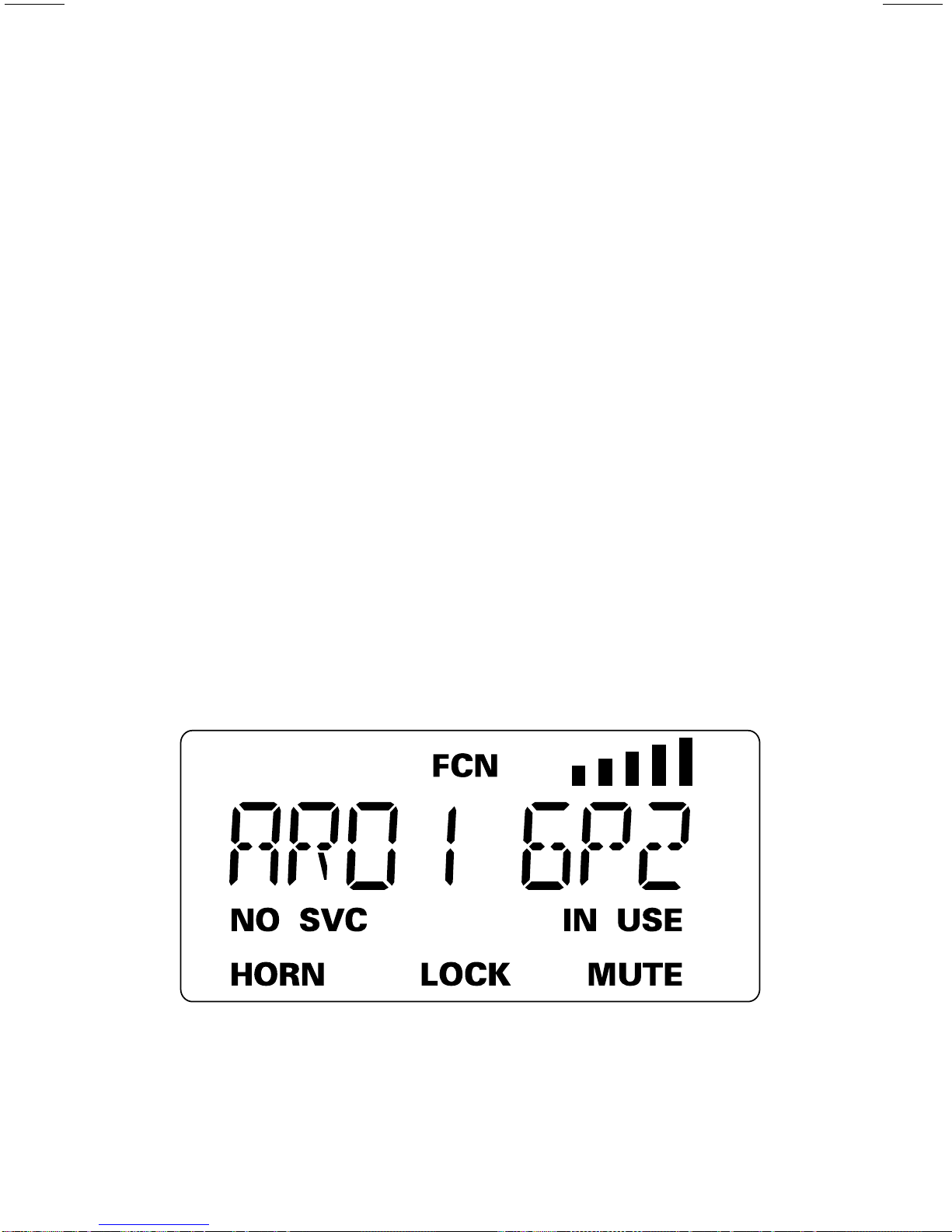
The radio's display is shown below. The character line is used to
display system or area and group or channel names and also operational
messages to the user. The line contains eight 14-segment alphanumeric
characters. The 8 characters are used to show the various operating conditions
of the radio.
Figure 2. Sample Dual Format MDR Display
13
Page 14

Messages
During GE-MARC radio operation, messages are displayed on the 8character line to show control information, such as system busy or call denied,
or messages associated with the radio's operation such as volume, or
RETRYING. These messages are described below.
BUSY Indicates an attempt to place a call has been made but the
selected trunked system does not have any available channels.
If the "Call Retry" option has been enabled through radio
programming, RETRYING is displayed instead and the radio
retries at 5 second intervals, up to 15 times unless END is
pressed, a channel is acquired, or an out-of-range condition
occurs.
RETRYING Indicates the radio is attempting to establish a channel.
WAIT Indicates the radio is acquiring a channel after call origination
has begun.
Status Indicators
Eight status indicators show the various operating characteristics of the
radio. Indicators are displayed to show the current operating status of the
radio.
FCN Indicates an extended function is currently being selected.
Indicates the transmitter is active.
NO SVC Indicates the radio is out of range of a system or the control
channel is not available.
IN USE Indicates the radio is receiving a signal on the selected channel or
group.
HORN Indicates the radio is configured to notify the user via an external
alarm that an individual call has been received.
LOCK Indicates the handset keypad is locked.
MUTE Indicates the handset has the transmit audio disabled (only valid
during duplex operation).
14
Page 15

ALERT TONES
The DUAL FORMAT MDR radio generates a set of unique alert tones to
indicate operating status. The following section identifies and describes the
alert tones used in the DUAL FORMAT MDR radio for Conventional,
GE-MARC, and EDACS applications.
EDACS APPLICATIONS
CALL If programmed, a short tone is sounded whenever the Push-To-Talk
ORIGIN- (PTT) button is keyed and the radio has acquired a channel.
ATE This tone indicates the user may begin communications.
ALERT
CALL QUEUED If one short, high pitched tone sounds after the transmitter
is keyed, this indicates that the system has placed the request in a
queue. This tone sounds at both the transmitting unit and the
receiving unit(s), indicating to the user on the receiving end that
they will receive a call shortly. If the PTT is unkeyed while in
queue, the radio autokeys (Automatically keys) push-to-talk when
a channel becomes available (see AUTOKEY).
AUTOKEYWhen the PTT is keyed to place a call on the system, but the PTT
is released before the channel is assigned (e.g. a queued call), the
radio automatically keys on the channel when it gets the
assignment. The radio generates a long beep and holds the
transmitter keyed for two seconds. Pressing the PTT button keeps
the channel and sends the message before this two second time-out
has expired.
SYSTEM BUSY If you key the PTT bar and hear three short, medium
pitched tones, this indicates that the receiving party is already on
the system or the system is busy and its queue is full. You must
rekey later to access the system.
CALL DENIEDA single low pitch beep sounds when the PTT switch is keyed
and the request is denied by the system. This happens if the unit is
an invalid user or if the unit is requesting an unavailable service.
OUT OF A single low pitched tone sounds immediately after the PTT
RANGE switch is keyed /indicating the radio is out of range of the
SYSTEM repeater. The radio tries to place the call for a short period (3
INOPER- seconds) after the initial attempt. The radio generates a second
ATIVE low pitched tone when it gives up trying to place the call. The
15
Page 16

system is off the air or the radio needs servicing when the radio is
within calling range, and these tones are heard.
GE-MARC APPLICATIONS
CALL RE- If programmed, a single alert tone sounds when a group call is
CEIVED received and a two tone alert (one high followed by one low
ALERT tone) sounds for an individual call.
CALL WAIT is momentarily displayed when a call is being placed.
ORIGINATE Then a three-tone alert sequence is sounded to indicate the
ALERT call origination is complete. This indicates a channel was
acquired and is ready for normal conversation.
INVALID CALL A low frequency tone is sounded for one second
ORIGINATE immediately after pressing PTT and the display does not show
ALERT WAIT. This indicates a call was attempted within a group that
is not enabled for call originate or an invalid dispatch overdial
call was attempted.
SYSTEM A low frequency tone is sounded for one second after attempting
TONES to place a trunked call and BUSY is displayed. This indicates
that the GE-MARC system is busy. If the "Call Retry" option
has been enabled through programming, the radio retries at 5
second intervals, up to 15 times unless END is pressed, a
channel is acquired, or an out-of-range condition occurs.
OUT OF If NO SVC is displayed and five beeps are sounded after
RANGE attempting to place a trunked call, then the radio is out of range
ALERT of the GE-MARC system. If the beeps sound when the radio is
within known range of the system, the radio may need
servicing. Once these tones have sounded, the user cannot
initiate another call for 20 seconds.
CARRIER (GE-MARC and Conventional operation) A pulsed tone
CONTROL signal is sounded continuously for a pre-programmed time PTT
TIMER after is pressed. After nine seconds of pulsing the alert tone, the
radio unkeys the transmitter and communications are
interrupted. While the tone is pulsing, the user can release and
press PTT again to reset the timer and resume the conversation.
In conventional mode, the radio unkeys and beeps until PTT is
released.
16
Page 17

SYSTEM TONES The GE MARC radio may generate other system tones to
alert the user of custom programmed events. Contact the
GE-MARC system operator for details about these alert tones.
OPERATION
GENERAL
Removing and Replacing Handset
The positive latch handset holder can be mounted vertically or horizontally
without worry of the handset being easily dislodged. The large knurled nut on
the bottom of the holder can be loosened and the holder adjusted for proper
usage. Tighten the knurled nut securely after the holder is adjusted.
Remove the handset by grasping it and simultaneously pressing the release
button on the handset holder, while lifting upward and away from the holder.
Replace it i n the holder with the top portion of the handset resting in the latch
depression and press the handset firmly onto the holder until the latch
mechanism snaps into place.
Turning The Radio ON/OFF
The radio is powered ON by pressing the POWER button at the bottom of
the handset. A self diagnostic test is performed when the radio is first turned
on if enabled through programming. To turn the radio OFF press POWER
again.
Volume Adjust
The user can adjust the volume at any time using the VOLUME UP and
VOLUME DOWN buttons. If the volume is adjusted while a call is in progress,
no audible beeps are heard. If no call is in progress, a short beep is heard, in
addition to the visual indication, if enabled. Additionally, the user selected
off-hook volume level is saved separately from the user selected on-hook
volume level.
EDACS OPERATION
(Features marked * are available in GE-MARC and EDACS
systems.)(Area applies to GE-MARC only.)
17
Page 18

System/Area Selection-Ramping Names*
The operator can ramp through the programmed system names list by
pressing and releasing the * key.
If the radio is programmed for a non-split display then the selected talk
group or conventional channel name is displayed when the radio is idling. The
first time the * key is pressed the radio displays the selected system name. This
name remains on the display for the programmed display timeout period. If the
* is released and then pressed again during this time the radio ramps to the next
system name in the list.
If the radio is programmed for a split display then both the selected system
and group are displayed when the radio is idling. The first time the * key is
pressed the radio ramps to the next system name in the list.
The ramp direction through the system name list is selectable. It is toggled
by pressing the FCN key.
System/Area Selection-Direct Number Entry*
Direct system/area selection can be made by entering (1) the system/area
selection digit(s), (2) pressing FCN, (3) pressing *. If an invalid number is
entered, the first system/area is selected.
Group Selection-Ramping Names*
The desired group is selected by pressing and releasing #. The ramp
direction of the group selection is changed by pressing FCN and then #.
Group Selection-Direct Number Entry*
Direct group selection can be made by entering (1) the group selection
digit(s), (2) pressing FCN, (3) pressing #. If an invalid group number is
entered, the first group is selected.
18
Page 19

Unlocking The Radio*
After the mobile is locked the user can unlock the mobile by keying in th e
lock code. If an incorrect digit is entered simply start over with the correct
code. If the lock code is forgotten, contact the system operator.
Locking The Radio*
The radio can be locked by pressing FCN followed by 7 PRS. The LOCK
icon is displayed. In this mode calls cannot be originated. This feature is
operational only if a lock code is entered during radio programming. Lock
codes can be 1 to 15 digits long.
Backlight*
The backlight function can be toggled on or off by pressing FCN followed
by 2 ABC. The intensity of the backlight cannot be changed.
Programmable Flex Keys*
Flex keys automatically recall and execute the function stored at that
location without further user intervention. Pressing A, B or C activates the
function.
Interconnect Dialing
To place an interconnect call, the user simply enters the desired number
using the digit (9-0) keys and presses the SEND key.
REDIAL Key*
Pressing the FCN key and then the SEND key, redials the last number
dialed.
Individual Call Dialing
To place an individual call, the user enters the desired LID number and
presses the PTT.
Individual Call Dialing - Con't.
To program the Flex Keys enter the following key sequence:
1. Enter the desired phone number/LID.
19
Page 20

2. Press the "*" key i f the number is a phone number or the "#" if the
number is a radio LID or dispatch overdial/ID.
3. Press the STO key.
4. Press the A, B, or C key that is to be associated with this call
number.
When a Flex Key i s P C programmed, it is locked, thus preventing the user
from re-programming its function.
Individual Call Notification
(EDACS Only)
When an individual call is received the caller's ID is stored and is displayed
for a programmable time period. After the display time has expired, the last
individual call received is recallable by pressing the RCL button or entering
Special Call mode. The caller's ID is not saved if the radio is turned off.
The user is alerted to the presence of missed individual calls via one of two
methods. The default first method is for the radio to display "C*" as the first
two characters in the display. The alternate method allows the user to PC
program an eight character alphanumeric such as "*MSG*". In combination
with these notification methods, the personality can be set-up so that the radio
beeps until the user clears the call or toggles the hookswitch.
Storing An Individual Call ID
This type of call is dynamically stored to the call list by following the
following steps:
1. Enter the desired individual call ID then "#" followed by the STO key.
2. Enter the two digit storage location for the number (00 to 50).
The new individual call ID is now added to the call list.
Using Special Call Lists*
In the Dual Format MDR, the difference between a "Call List" and "Special
Call List" is that the Call List consists of user modifiable phone numbers and
radio LIDs. It operates similarly to a pre-stored phone list i n a cellular phone.
A "Special Call List" is PC programmable and is not user modifiable.
20
Page 21

Storing A Telephone Number To The Call List*
The number of dial locations (10, 20, 30, 40, or 50) available is set through
radio programming. The maximum number of digits stored in any location is
14. The user may dynamically add phone numbers to the call list by following
these steps:
1. Enter the phone number, then "*", followed by STO.
2. Enter the two digit storage location for the number (00 to 50).
The new phone number is now added to the call list at the specified
location.
Recalling calls from the call list*
Each pre-stored call number has a corresponding phone number. To dial
the phone number, select the 2 digit call number and press RCL. Alternately,
the user can scroll through the call list using the RCL key to scroll forward
through the list.
Simplex Operation*
The user can choose to terminate duplex operation and still maintain the
interconnect call in progress by pressing FCN followed by 5 JKL. This key
sequence toggles between simplex and duplex operation.
*/System Key usage
The "*/System" ramp button is used in multiple contexts. When pressed
while in monitor mode (i.e. radio is not in a special or interconnect call) the
radio ramps through available systems in one direction. If FCN followed by
"*/System" is pressed, system ramping takes place in the opposite direction.
If this key is pressed after any key other than FCN the "*" is returned.
END key Usage
The END key is used to terminate interconnect and individual calls.
Additionally, if the radio is programmed as a supervisory radio this key can be
used to terminate activity, i.e. clear emergencies, drop calls, etc.
21
Page 22

Last Digit Clear And Display Clear*
To clear the last digit entered in the display, momentarily press CLR. To
clear the entire display, press and hold CLR for at least one second.
For functions without associated icons the current status is displayed by
pressing FCN key followed by the desired function. At that time the current
state is displayed in the handset's character display. If the state is to be
changed, the user must again press the desired function key at which time the
new state is displayed. Once the user is satisfied with the selection, let the
display expire by not pressing any keys, or press END to signify that the
current activity has ended.
1/HORN Key*
The horn alert option can be pre-programmed to: 1) generate a 1 second
horn blast, 2) generate three 1/2 second horn blasts, or 3) generate a continuous
horn blast when a call is received. This function is enabled or disabled by
pressing FCN and then 1 QZ. Pressing PTT during the alert tone prevents
blowing the horn. The horn alert remains enabled for subsequent calls until
disabled.
4/EXT SPK*
The external speaker option routes receive audio to an externally mounted
speaker. To enable the external speaker, press FCN followed by 4 GHI.
Toggling this function provides the user with the capability to have private
conversations or allow other passengers in the vehicle to hear the conversation.
The character display shows "INT SPKR" if the internal speaker is currently
active. To toggle the state of the external speaker press "4/EXT SPK" key
twice while the "FCN" icon is on.
NOTE
The external speaker is disabled in the duplex mode when the handset is
off-hook. This is set up by PC programming.
5/SIMPLX
When operating in the simplex mode, the MUTE icon follows the state of
the transmit audio. While in simplex mode, PTT must be pressed prior to
speaking. (NOTE: Applicable only in the interconnect mode.)
22
Page 23

6/MUTE*
This function enables the user to mute the transmit audio when operating
in the duplex mode. To disable the microphone so the called party cannot hear
the conversation, press FCN followed by 6 MNO. MUTE is displayed.
Re-enable the microphone using the same key press sequence. The call is
muted only for the duration of the current interconnect call.
8/SCAN
(EDACS and Conventional Modes Only)
Scan operation is controlled by this key sequence (i.e. FCN followed by
8/SCAN).
9/SCAN ADD
(EDACS and Conventional Modes Only)
Press FCN followed by 9/SCAN ADD to enter scan add/delete mode. In
this mode, group ramping is available using #/Group. If the group displayed
has scan enabled the first letter of the group contains an "S". In conventional
mode the first character may be a 1 or 2 indicating priority.
0/SPC
Entering FCN followed by 0/SPC accesses the Special Call List. This list
is a programmable set of call numbers that the user can invoke by scrolling to
the desired call number in the alpha-numeric display and then depressing the
PTT. Scrolling forward through this list is done by pressing #/GROUP.
Scrolling backward through this list is done by pressing FCN followed by
#/GROUP. (See Special PC programming functions in TQ-3373, for
programming of the Special Call List.) Terminate Special Call List access by
pressing END.
A/Testmode
Test Mode is entered when the operator presses FCN followed by A. This
function can be disabled by PC programming.
B/Pause
A pause is entered into a stream of DTMF numbers being dialed via the
keypad. The operator enters FCN followed by B. The length of pause is PC
programmable.
23
Page 24

C/Call Timer*
The call timer function (C/CAL TMR) causes the time duration for the
current interconnect call to be displayed. Note that the call timer starts when
an interconnect call is initiated. To display the call timer during a
conversation, press FCN and then C. The time display is automatically
removed after a preset time-out or can be removed from the display by pressing
CLR.
PROGRAMMABLE OPTIONS
Call Time
-outs
The Dual Format MDR provides several time-out options to accomodate
user needs. They are summarized below:
Carrier Control Timer (CCT)
This timer is provided to limit continuous transmit time (when not i n a
duplex mode of operation). A single value can be selected that applies
to all trunked operation. Each conventional channel has the option of
enabling or disabling the timer on a per channel basis.
Voice Scan Lockout Timer
Provides a time limit that disables group scanning following initiation
of a voice call.
Special Call time-out
Drops the radio out of special call mode after a specified period of
operator inactivity.
Individual/Interconnect Call time-out
A time-out that drops the radio out of an individual/interconnect call
after a specified period of time.
Emergency
Any one of the three Flex Keys (A, B, or C) can be programmed to
function as the emergency button.
24
Page 25

If the radio is programmed as a supervisory radio, it is allowed to clear
emergencies from the system. When the message "EMRGNCY" is displayed,
pressing the END button followed by the Emergency button (A, B, or C) causes
the radio to attempt to clear the emergency.
Automatic Login
The Dual Format MDR supports Automatic Login for EDACS trunked
systems.
Wide Area System Scan
The Dual Format MDR supports Wide Area Roaming. When scanning,
there is a programmable time interval that determines when the radio starts
scanning the next site.
Supervisory Mode
When a Dual Format MDR radio is programmed as supervisory, it is
capable of handling all normal supervisory functions.
Programmable Audio/Display
Each EDACS system has a programmable option to handle display and
audio during emergency conditions. When an emergency occurs, the display
option can be programmed to hold the display unchanged until the PTT button
is pressed or the emergency is cleared. The audio option, similarly, causes the
radio to remain muted until PTT is pressed or the emergency is cleared.
Priority System Scan
This option allows the MDR to search for a second operating system while
locked onto the control channel of the selected system. If a second control
channel is found, the radio switches to that system. The scan frequency is
programmable.
Group Options
Each EDACS trunked system uses a set of groups. Each set allows for a
home Group ID, Dynamic Regroup/encoding, and Emergency calls. In
addition to each group ID the following options are supported.
TX Disable-Group Option
This option prevents keying a radio on a particular group (monitor only).
25
Page 26

Rx Disable-Group Option
This option prevents unmuting a radio on a particular group.
Control Channel Limits
This option provides for limited scanning of a frequency set for a control
channel. When programmed, the radio is only capable of scanning a subset of
channels for a control channel. This is useful in large wide area scanning
systems to speed up the scan process.
Conventional Failsoft Channel
This option selects the channel within a site for operation should the site
drop into conventional failsoft mode.
GE-MARC OPERATION
Placing A Dispatch Call
1. Select desired system/area and group.
2. Press PTT.
3. The display changes from the selected system/area and group display to
WAIT while the radio is acquiring a repeater.
4. The radio sounds a three-tone alert signal when the communications
channel is acquired.
5. If the radio is out of range of the selected system, 4 short and 1 long beep is
heard and NO SVC is displayed for approximately 20 seconds. While NO
SVC is displayed, no attempts can be made to place a call. If a new area is
selected NO SVC turns off and the call can now be attempted in the new
service area. If all available repeaters are busy when the call is attempted,
1 long beep is heard and BUSY is displayed. If the call retry option has
been enabled through programming, RETRYING displays instead of the
BUSY message.
6. The selected group or Special call item is displayed again after the call is
completed.
26
Page 27

Placing An Interconnect Or Dispatch Overdial Call
There are four methods to place an interconnect or dispatch overdial call.
METHOD 1: For interconnect, enter phone number and press SEND. For
overdial, press FCN and then 3 DEF. OVERDIAL is
displayed on the character line. Enter the dispatch ID (2 or 4
tone sequence; e.g., *1809 or 18092310). Press SEND.
METHOD 2 Press FCN followed by SEND to automatically redial the last
phone number or dispatch ID.
METHOD 3 Recall a previously stored dispatch ID or phone number from
memory and then press SEND.
METHOD 4 Enter the Special Call mode by pressing FCN and then
0/SPC, or enter Conference Call mode by pressing FCN and
then 8/CNF CALL, selecting a dispatch overdial or
interconnect call from the Special Call list and then pressing
SEND.
Storing A Dispatch Overdial Call
This type of call is dynamically stored to the call list by following these
steps:
1. Enter the desired individual call ID then press # followed by STO.
2. Enter the two digit storage location for the number (00 to 50).
The new individual call ID is now added to the call list.
3/OVERDIAL
Press FCN and then 3/OVERDIAL to enter the dispatch overdial mode
and OVERDIAL is displayed. In this mode the user may enter a tone set for a
dispatch overdial call and press PTT or SEND to send the call.
27
Page 28

8/CNF CALL
Press FCN and then 8/CNF CALL to enter the Conference Call mode.
This mode allows the user to encode a call from the Special Call list using the
selected group tone set.
Ending A Call
Calls can be ended three ways:
METHOD 1 Press END.
METHOD 2 A system disconnect or time out occurs. During a dispatch
call the time out occurs after 6 seconds of channel silence.
During an interconnect call timeout occurs after 30 seconds of
channel silence.
METHOD 3 Returning the handset to the holder.
NOTE
If a channel disconnect occurs before the conversation ends, the call must
be initiated again. To avoid confusion it is recommended that a procedure
be set up requiring the originator of the call to re-establish
communications. Two or more operators originating a call simultaneously
normally acquire two different channels making communication
impossible.
Receiving A Call
When a call is received by the radio, the call is decoded. If enabled, a
single alert tone sounds indicating a group call was received or a two tone alert
sounds if an individual call was received. The display shows the group identity
when receiving a group call and the * INDV * display when an individual call
is received.
To answer a simplex dispatch call, pick up the handset and use PTT to
transmit to the caller. To receive an interconnect call, press * to answer the
call and place the unit in duplex.
Duplex operation must be enabled by the system operator for the tone set
being used during duplex mode. If auto-interconnect is enabled for the
system/area and the individual tone set being decoded, the user enters duplex by
removing the handset from the cradle. If the handset has already been removed
28
Page 29

from the cradle when the call is received, the user presses * to enter duplex
mode.
NOTE
Pressing FCN and then 5 JKL during duplex operation toggles the radio
into simplex mode.
CONVENTIONAL MODE OPERATION
1. Select the conventional mode of operation by pressing *. If more than one
channel is available in the conventional system, press # to select the other
channels.
2. Determine if the channel is in use before making the call. Press END to
momentarily disable the squelch and monitor the channel for activity.
Alternatively, remove the handset from the holder to disable Channel
Guard. This allows you to monitor the channel without disabling the
squelch.
3. Press PTT and send the message.
Direct Mode Operation (Optional)
The direct mode provides short range, line of sight communications for
radios with the talk-around option installed. While in the direct (or
talk-around) mode, the radio will not function in the trunked mode.
1. Select a direct mode channel using the #.
2. Determine if the channel is in use before making the call. To monitor the
channel press END to momentarily disable the squelch. Alternately,
removing the handset from the holder allows monitoring of the channel
without disabling the squelch (Busy Tone is disabled). If the channel is in
use, IN USE is displayed.
3. Press PTT and send the message. BUSY is displayed when the channel is
active.
29
Page 30

MAINTENANCE AND BASIC CARE
ANTENNA REMOVAL
It is strongly recommended that your antenna be removed from its
mounting prior to passing through an automatic car wash in order to prevent
antenna and/or vehicle damage. See your antenna instruction guide for
instructions on how to safely remove the antenna from its mounting.
FUSE REPLACEMENT
The radio is protected by one or more fuses located in the cables connected
to the vehicle power source(s). If the radio fails to operate, the problem may be
a defective fuse. Replace the fuse(s) with a similar type and size (see list
below). These fuses may be obtained from the radio supplier or most electrical
supply stores. If, however, the trouble persists (continues to blow fuses or
inoperative radio), check with the radio supplier.
Radio Power ( Orange lead) 15 amp Fast Blow Type AGC15
Ignition Sense (Red lead) 2 amp Fast Blow Type AGC2
JUMP STARTING THE VEHICLE
Before jump starting or charging the vehicle battery, it is strongly
suggested that the main power fuse, located in the orange lead, be removed.
This insures that the radio is protected from damage in the battery charging
process. Replace the fuse when charging is completed.
CLEANING INSTRUCTIONS
The handset can be cleaned with a damp cloth, using a mild solution of
liquid detergent and water or with a soft cloth and furniture polish. Never use
an abrasive or a petroleum based solvent cleaner.
30
Page 31

AVAILABLE OPTIONS
The following equipment options are available for the radio. Refer to your
radio supplier for ordering information.
Table 1. Dual Format MDR Optional Accessories
OPTION
DESCRIPTION PART NUMBER
PMAN1L 800 MHz roof mount antenna with TNC 19B209568P5
connector
PMCC1H Handset extension cable (no coil), 18 feet, 19B801636P1
requires option PMCN1A
PMCC3S Handset cable (coiled), 6 feet stretched 19D901619P4
PMCC9M External speaker cable, 18 inches 19A149590P8
PMCD1W External speaker cable, 16 feet, 19A149590P10
requires option PMZM1K
PMCD7Z External option cable, 3 feet 19C851585P14
PMCD9A Power cable, 18 feet 19B801358P17
PMCN1A In line connector 19A705839P1
PMLS1F Speaker, MIL-STD-810C & D, 5" x 5", requires 19A149590P1
options PMCD7Z & PMCC9M
PMPD1A Noise suppression kit 19A148539G1
PMSU1C Alarm (horn) relay kit, requires option 19A705499P1
PMCD7Z
PMTA1B Talk-around kit 344A3803G2
PMZM1K External speaker kit, requires option PMCD7Z,
includes options PMLS1F and PMCC9M
PMZM5V Handset extension cable kit, includes options
PMCC3S, PMCC1H and PMCN1A (2)
31
Page 32

FREQUENTLY CALLED NUMBERS
MEMORY LOCATION
01
02
03
04
05
06
07
08
09
10
11
12
13
14
15
16
17
18
19
20
21
22
23
24
25
26
27
28
29
30
31
32
33
34
35
36
37
38
39
40
41
42
43
44
45
NAME TELEPHONE NUMBER
32
Page 33

FREQUENTLY CALLED NUMBERS
MEMORY LOCATION
46
47
48
49
50
NAME TELEPHONE NUMBER
33
Page 34

NOTES:
Page 35

WARRANTY
A. Ericsson GE Mobile Communications Inc. (hereinafter "Seller") warrants to the original purchaser for use
(hereinafter "Buyer") that Equipment manufactured by Seller shall be free from defects in material, workmanship and
title, and shall conform to its published specifications. With respect to any Equipment not manufactured by Seller
(except for integral parts of Seller's Equipment to which the warranties set forth above shall apply). Seller gives no
warranty, and only the warranty, if any, given by the manufacturer shall apply. Batteries are excluded from this warranty
but are warranted under a separate Nickel-Cadmium Battery Warranty.
B. Seller's obligations set forth in Paragraph C below shall apply only to failures to meet the above warranties (except
as to title) occurring within the following periods of time from date of sale to the Buyer and are conditioned on Buyer's
giving written notice to Seller within thirty (30) days of such occurrence:
1. for fuses, incandescent lamps, vacuum tubes and non-rechargeable batteries, operable on arrival only.
2. for parts and accessories (except as noted in B.1) sold by Seller's Service Parts Operation, ninety (90) days.
3. for all other Equipment of Seller's manufacture, one (1) year.
C. If any Equipment fails to meet the foregoing warranties, Seller shall correct the failure at its option (i) by repairing
any defective or damaged part or parts thereof, or (ii) by making available at Seller's factory any necessary repaired or
replacement parts. Any repaired or replacement part furnished hereunder shall be warranted for the remainder of the
warranty period of the Equipment in which it is installed. Where such failure cannot be corrected by Seller's reasonable
efforts, the parties will negotiate an equitable adjustment in price. Labor to perform warranty service will be provided at
no change only for the Equipment covered under Paragraph B.3, and only during the first three (3) months following the
date of sale to the Buyer. Thereafter, labor will be charged at prevailing rates. To be eligible for no-charge labor, service
must be performed by an authorized General Electric Service Station or other Servicer approved for these purposes
either at its place of business during normal business hours, for mobile or personal equipment, or at the Buyer's
location, for fixed location equipment. Service on fixed location equipment more than thirty (30) miles from the Service
Station or other approved Servicer's place of business will include a charge for transportation. Equipment located offshore is not eligible for no-charge labor.
D. Seller's obligations under Paragraph C shall not apply to any Equipment, or part thereof, which (i) has been
modified or otherwise altered other than pursuant to Seller's written instructions or written approval or, (ii) is normally
consumed in operation or, (iii) has a normal life inherently shorter than the warranty periods specified in Paragraph B, or
(iv) is not properly stored, installed, used, maintained or repaired, or, (v) has been subjected to any other kind of misuse
or detrimental exposure, or has been involved in an accident.
E. The preceding paragraphs set forth the exclusive remedies for claims (except as to title) based upon defects in or
nonconformity of the Equipment, whether the claim is in contract, warranty, tort (including negligence), strict liability or
otherwise, and however instituted. Upon the expiration of the warranty period, all such liability shall terminate. The
foregoing warranties are exclusive and in lieu of all other warranties, whether oral, written, expressed, implied or
statutory. NO IMPLIED OR STATUTORY WARRANTIES OF MERCHANTABILITY OR FITNESS FOR PARTICULAR
PURPOSE SHALL APPLY. IN NO EVENT SHALL THE SELLER BE LIABLE FOR ANY INCIDENTAL,
CONSEQUENTIAL, SPECIAL, INDIRECT OR EXEMPLARY DAMAGES.
This warranty applies only within the United States.
ECX-362R
6/90 Printed in U.S.A.
Page 36

Police
State Police
Fire
Poison Control
Ambulance
Life Saving and
Rescue Squad
EMERGENCY NUMBERS
Printed in U.S.A.
 Loading...