

Page 1
UNIVERSAL TRANSIENT BARRIER
17,5
INSTALLATION INSTRUCTIONS
PRODUCT SERIES
UTB - xx
90
1. PREPARATION
DANGER: Possible electrical shock or burn
hazard. Qualified personnel should only install this
product. Failure to lockout electrical power during
installation or maintenance can result in fatal electrocution or
severe burns. Before making any connections to this
electrical panel please ensure that power has been removed
from all associated wiring, electrical panels, and other
electrical equipment.
CAUTION NOTES:
1. The installation of this Universal Transient Barrier (UTB)
should follow observe nationally recognized codes of
authorities having jurisdiction to ensure correct and safe
operation.
2. Check to ensure that the maximum continuous operating
voltage Uc of the UTB selected is higher than that
expected on the circuit being protected.
3. It is important to ensure that the maximum line current
rating IL of the UTB is not exceeded.
4. Check that the maximum operating frequency of the
circuit does not exceed that of the UTB.
5. The ground (earth) terminal must be connected to a low
impedance earth (<10 ohms) for correct operation.
6. Do not perform a “Flash Test” or use a Megger to test
circuits that are protected with these UTB units. This may
damage the UTB(s) and affect the insulation readings
being performed.
7. Do not attempt to open or tamper with the UTB unit in any
way as this may compromise performance and will void
warranty.
2. INTRODUCTION
The CRITEC Universal Transient Barrier (UTB) has been
designed to protect equipment from the damaging effects of
surges on low voltage data, control and signaling lines.
Damage can also occur when surges entering the equipment
via the mains power cabling. ERICO recommends the
installation of additional surge protection on these mains
circuits. The CRITEC DSD series compliments the UTB
series for such applications.
UTB units are available in a number of different operating
voltages to suit the specific application intended. The TA and
SA models are intended to protect equipment connected to
telephone subscriber lines.
3. ELECTRICAL CONNECTION
Please follow the sequence indicated:
1. First, ensure that power is removed from the area and the
circuits to be connected.
2. Connect line side wiring to the UTB screw terminals
marked LINE (a, b). The “line side” of the UTB is the
“exposed side” where the surge is expected to originate.
3. Connect equipment side wiring to the UTB screw terminals
marked EQUIP (a’, b’). The “equipment side” of the UTB is
the protected side and wires to the equipment being
protected.
4.The UTB should be installed as close to the equipment
being protected as possible. Where protecting long cable
runs (< 30 meters), a UTB unit should be installed at either
end of the cable.
5. Connect the UTB’s ground screw terminal to a low
impedance ground using as direct a path as possible. This
“ground” should also be referenced to the equipment being
protected. When the UTB is installed on a DIN rail,
grounding of the unit can be achieved by connecting the rail
to ground.
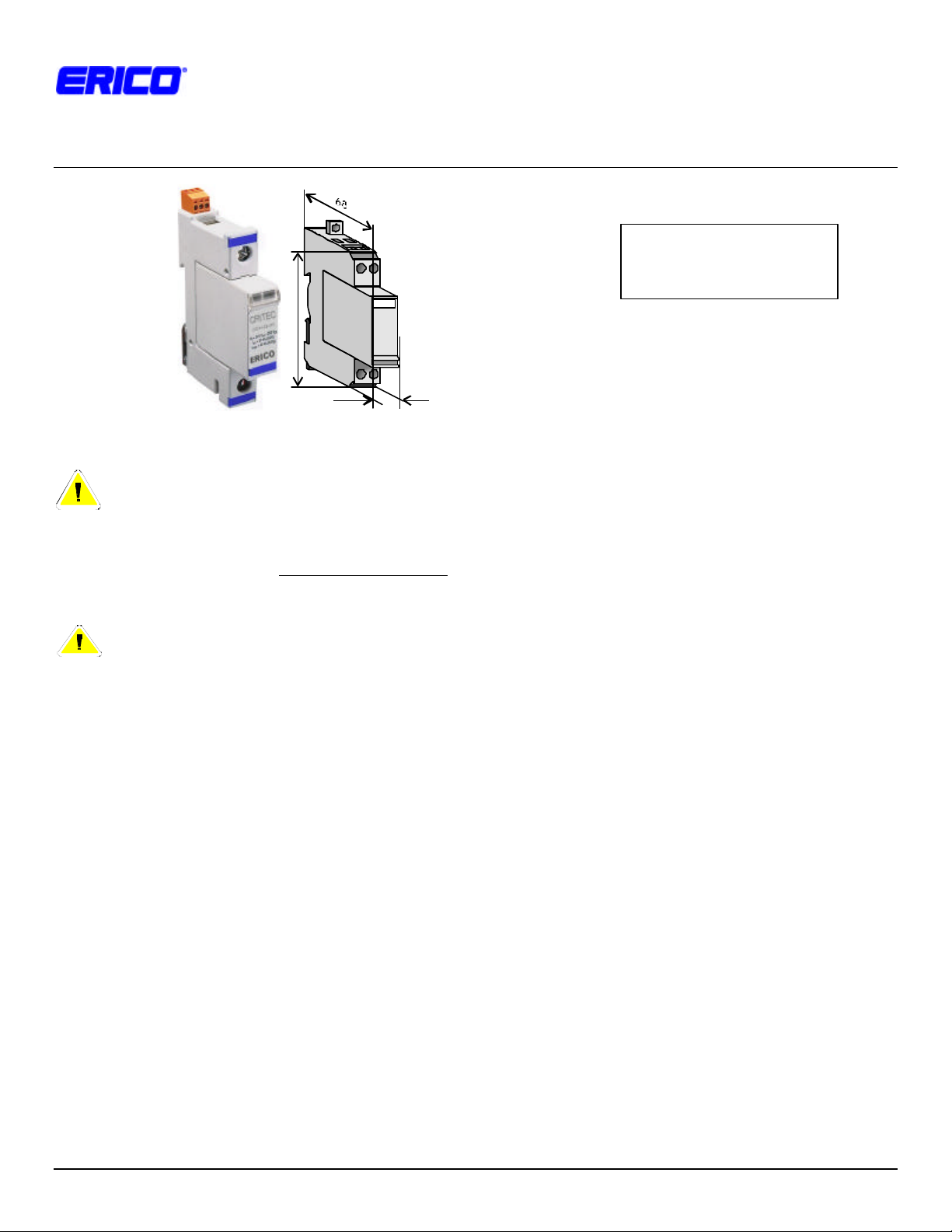
4. MOUNTING
UTBs are designed to clip to 35mm (top hat) DIN rails
(standard EN50022) set in the horizontal position with the
UTB securing clips towards the bottom of the rail and the
label text facing the correct way up.
2003 ERICO Inc, 34600 Solon Rd, Solon, OH 44139 Phone (440) 248-0100 Fax (440) 519-1675 Page 1 of 2
Page 2
UNIVERSAL TRANSIENT BARRIER
INSTALLATION INSTRUCTIONS
5. MAINTENANCE
Failure of a UTB is usually indicated by interruption of data or
a fault on the signal (control) line. The UTB has been
designed for simple plug-in modular replacement, without
the need to disturb circuit wiring.
Before removing a UTB module from service, ensure that the
power has been removed and if possible “locked out”.
Qualified personnel should only undertake replacement of
UTB modules. Replacement plug-in modules are available.
NOTE: It is very important to ensure that the new module is of
the same type and voltage as that being replaced.
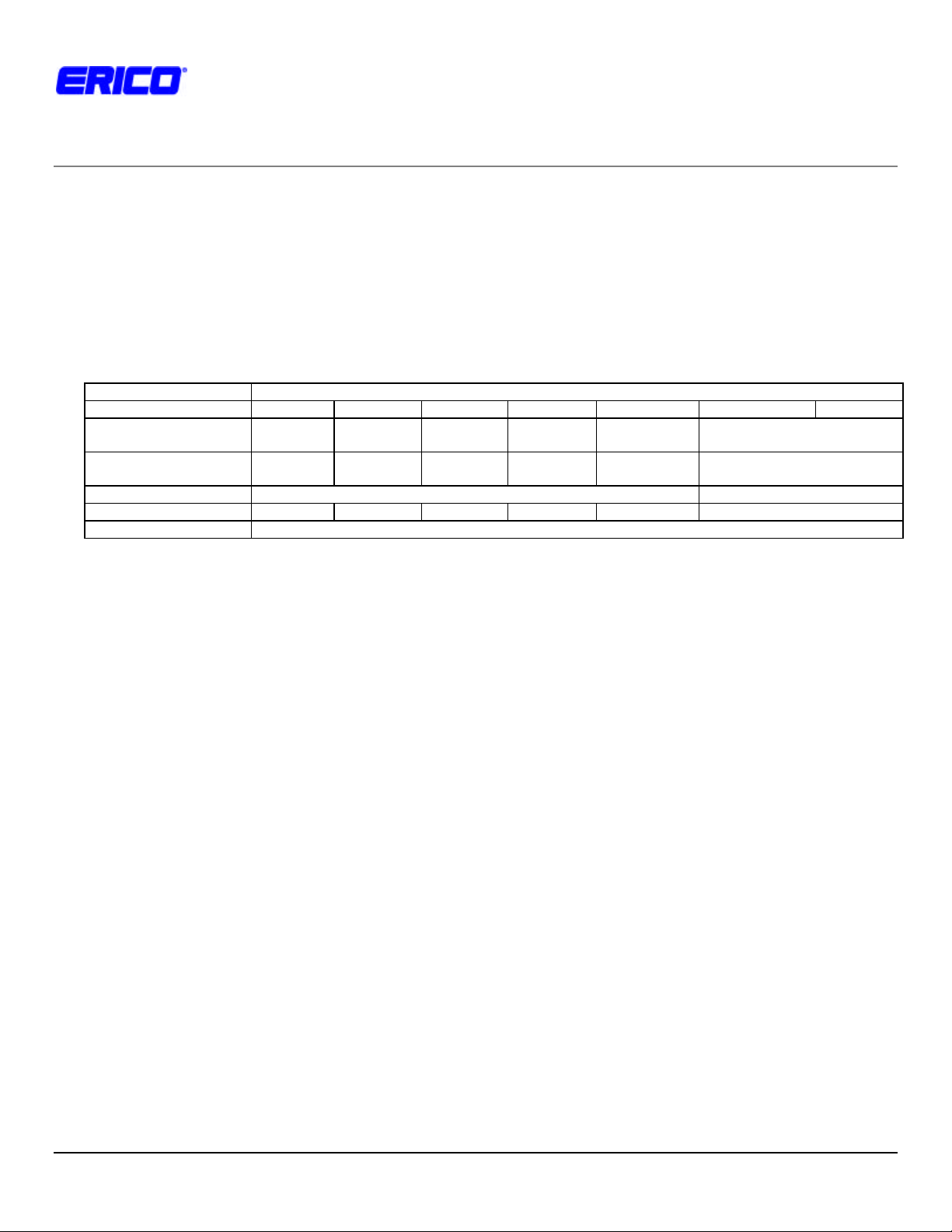
Table 1. UTB operating specifications
Operation:
Model UTB-5 UTB -15 UTB-30 UTB-60 UTB -110 UTB -SA UTB -TA
Nominal System
Voltage Un
Max. Continuous
Operating Voltage Uc
Max. Line Current I
Frequency @ 3dB / 120? <500kHz <1MHz <2MHz <4MHz <2MHz <15MHz
Connections 6mm2 (#18AWG to #10AWG). Grounding via terminal or DIN rail connection
5V- 3V~ 15V- 10V~
7V- 5V~ 18V- 12V~
1.5A 160mA
L
- 21V~ 60V- 42V~
- 23V~ 64V- 45V~
- 120V~ Analog telephone circuits
- 150V~ -
2003 ERICO Inc Page 2 of 2 Doc: IPCR1100.DOC, Rev: 1.0, Date: 28 Mar. 2003
 Loading...