

Page 1
INSTRUCTION SHEET
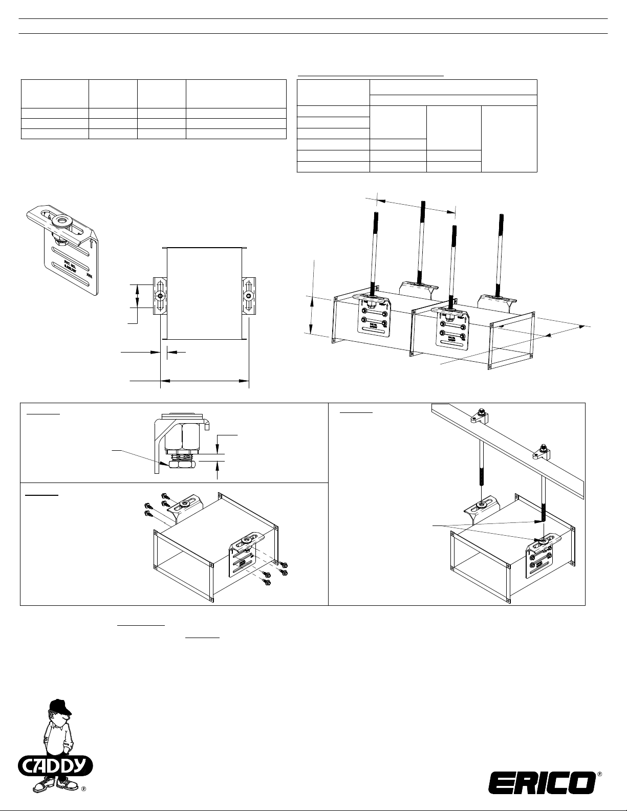
CADDY® ROD LOCK
Top-Mount Duct Bracket
Part Number
CRLD37TEG N/A 3/8" 600 lbs [2,650 N]
CRLDM8TEG 390017 M8 600 lbs [2,650 N]
CRLDM10TEG 390018 M10 600 lbs [2,650 N]
*Note: (4) screws are required for non-duct application.
**CRLD37TEG (3/8") and CRLDM10TEG (M10) were verified by the
SMACNA Testing and Research Institute to be acceptable
alternatives to the duct hanger systems described in the
/SMACNA HVAC Duct Construction Standards (HVAC-DCS)
®
ANSI
3rd edition, Chapter 5, Tables 5-1 and 5-1M
Article
Number
Rod Size
2-1/2" (64mm)
Slot Width
3/4" (19mm)
Typical
Duct Width
+ 1-1/2" (38mm)
Load Rating for
general applications*
(3.0 safety factor)
Rectangular Duct Application
Max. Half of Duct
Perimeter***
P/2 = 30"
P/2 = 72"
P/2 = 96"
P/2 = 120" -P/2 = 168" -- -P/2 = 192" -- --
***P/2 = (Duct Height) + (Duct Width)
3/8", M8, M10 Threaded Rod Sizes**
L = 10ft [3m]
"L" Dimension
Duct Height
Duct Width
60" (1,524mm) Maximum
"L" Dimension
L = 8ft [2.4m]
L = 5ft [1.5m]
Step 0:
Rotate lock nut
counter-clockwise
until reaches
stopping position
Step 1:
Install four (4)
self-drilling screws
(included) for
each bracket.
WARNING:
NOTE: All load ratings are for static conditions and do not account for dynamic loading such as wind, water or seismic loads, unless otherwise noted.
The customer is responsible for:
a. Conformance to all governing codes.
b. The integrity of structures to which the products are attached, including their capability of safely accepting the loads imposed, as evaluated by a qualified
engineer.
c. Using appropriate industry standard hardware as noted above.
SAFETY INSTRUCTIONS:
All governing codes and regulations and those required by the job site must be observed.
Always use appropriate safety equipment such as eye protection, hard hat, and gloves as appropriate to the application.
ANSI is a registered trademark of American National Standards Institute
CADDY, CADWELD, CRITEC, ERICO, ERIFLEX, ERITECH, and LENTON are registered trademarks of ERICO International Corporation.
Maximum open
position
ERICO products shall be installed and used only as indicated in ERICO product instruction sheets and training materials. Instruction sheets are available at 1.
www.erico.com and from your ERICO customer service representative.
ERICO products must never be used for a purpose other than the purpose for which they were designed or in a manner that exceeds specified load ratings.2.
All instructions must be completely followed to ensure proper and safe installation and performance. 3.
Improper installation, misuse, misapplication or other failure to completely follow ERICO's instructions and warnings may cause product malfunction, property 4.
damage, serious bodily injury and death.
Products that are manufactured using spring steel components shall be used only in a non-corrosive indoor environment. 5.
All pipe supports, hangers, intermediate components and structural attachments must ONLY be used as described herein and are NEVER to be used for any 6.
other purpose.
Step 2:
Lift duct into place.
Push bracket on
to threaded rod.
both sides
TECHNICA L SUPPORT:
www.erico.com
CFS474_E
1 OF 2
© 2013, 2014 ERICO International Corporation.
Page 2
INSTRUCTION SHEET
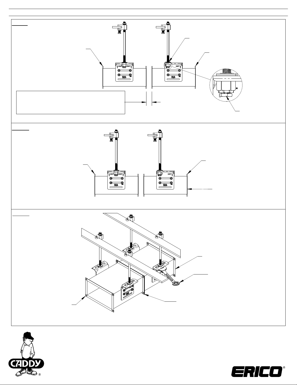
Step 3:
Position duct for assembly
Positioned at nearest end
Previously installed duct
Gap
1-1/2" [38mm] for Flanged duct
or
1/2" - 1" [13mm - 25mm] for Slip & Drive duct
Step 4:
Push duct together.
Previously installed duct
New duct
Tighten lock nut
New duct
Push new duct toward
previously installed duct.
Step 5:
Complete duct joint.
Previously installed duct
New duct
Fine adjust duct height by
wrench:
Clockwise = duct down
Counter-Clockwise = duct up
Complete duct joint for:
Flange connection
or
Slip & Drive connection.
CADDY, CADWELD, CRITEC, ERICO, ERIFLEX, ERITECH, and LENTON are registered trademarks of ERICO International Corporation.
TECHNICA L SUPPORT:
www.erico.com
CFS474_E
2 OF 2
© 2013, 2014 ERICO International Corporation.
 Loading...