

Page 1
SURGE DIVERTERS
INSTALLATION INSTRUCTIONS
Includes MPM Movtec Protection
Module Instructions
www.erico.com
Handbook No:
Handbook No:
HB-HBCR-111
HB-HBCR-111
© Copyright
© Copyright
ISSUE: 3 April 2003
Page 2

INSIDE FRONT COVER
(Blank)
Page 3

CONTENTS
Page
1. Warnings ... ... ... ... ... ... ... ... ... ... ... 4
2. Introduction ... ... ... ... ... ... ... ... ... ... 5
3. Protection Concepts .. ... ... ... ... ... ... ... 7
4. Mounting and Cautions ... ... ... ... ... ... 9
5. Voltage Ratings .. ... ... ... ... ... ... ... ... 10
6. Protection Mode .. ... ... ... ... ... ... ... ... 13
7. Connection Method ... ... ... ... ... ... ... 15
8. RCD, ELCB ... ... ... ... ... ... ... ... ... ... 20
Page
9. Isolation and Fusing ... ... ... ... ... ... ... 20
10. Status Indication and Alarms
... ... ... 22
11. MPM, Movtec Protection Module ... ... 24
12. Maintenance and Testing .. ... ... ... ... 27
13. Extended Warranty ... ... ... ... ... ... ... 28
14. Six Point Plan ... ... ... ... ... ... ... ... 29
15. Use of Mimic Panels ... ... ... ... ... ... 30
PAGE 3
Page 4
GLOBAL LIGHTNING TECHNOLOGIES
1. WARNINGS
• Prior to installation ensure that the
Movtec is of the correct voltage and
frequency, and is the type recommended for
the local power distribution, and for the
equipment being protected.
• Hazardous voltages may exist internally to
the units. The units should be installed
(and replaced) only by qualified personnel
in accordance with all relevant Electricity
Safety Standards.
• Do not power MPMs and three phase
connected Movtecs (Ph-N) without the
upstream neutral connected. Failure to do
so may damage the Movtecs and/or the
load.
• Where the MPMs/Movtecs are connected
to an earth, this must be a low impedance
earth (<10 Ω) for correct operation.
PAGE 4
• X1-X4 connections may be at phase voltages
dependant upon connection method.
• If connecting to the Movtec alarm outputs
do not exceed the maximum permissible
ratings as damage may occur.
• Movtecs must be installed in an
enclosure or panel, ensure this does not
cause their environmental ratings to be
exceeded.
• Do not “Megger” or “Flash Test” circuits
with Movtecs installed.
• The DINLINE Surge Counter (DSC) should
not be used in voltage sensing mode with
TDS-Movtecs. Voltage sensing mode is not
compatible with TDS-Movtecs.
• All instructions must be followed to ensure
correct and safe operation.
• Diagrams are illustrative only, and should
not be relied on in isolation.
Page 5

DINLINE INSTALLATION INSTRUCTIONS
2. INTRODUCTION
Movtecs are designed to protect mains
powered equipment from the damaging effects
of lightning and transients. They are ideal for
point-of-entry shunt protection applications
where robustness and high surge ratings are
required.
The Movtec family is designed to suit many
distribution systems including TN-C, TN-S,
TN-C-S and TT. They can be selected for use
with distribution systems with nominal
voltages of 110/120V, 220/240V and 277Vrms
at frequencies of 50/60 Hz.
The TDS Technology (Transient
Discriminating Suppressor) units are
specifically designed for distribution systems
that may feature poor voltage regulation
where the actual supply voltage may exceed
the nominal ratings for extended periods.
This Installation Manual details the preferred
procedure for the installation of the family of
Critec Movtec™ Surge Diverters.
The Critec Movtec family includes:
• Critec Movtec, Single Mode, enhanced
MOV technology units eg. (MT275V-135K-A)
• Critec TDS-Movtec, Single Mode, TDS
technology unit featuring high over-voltage
withstand for added robustness (TDS-MT-
277)
• Critec TDS-Movtec, Three Mode, TDS
technology unit featuring high over-voltage
withstand for added robustness (TDS-MTU)
TDS-Movtec units are coloured blue for easy
identification, while enhanced MOV
technology units are coloured red.
In this manual, reference to “ Movtec” also
includes “TDS-Movtec”.
PAGE 5
Page 6
GLOBAL LIGHTNING TECHNOLOGIES
This manual also details the installation of
the MPM (Movtec Protection Module). The
MPM is a supplied enclosure with three
Movtecs and a high energy neutral to earth
protection device for three phase protection.
The MPM is often used where Movtecs can not
be fitted in an existing switchboard and must
be mounted externally. Therefore the Movtec
installation instructions are also applicable to
the MPM. Section 11 gives details which are
specific to the MPM.
Two standard MPMs are available:
• Critec TDS-MPM, Single Mode, TDS
Technology unit (uses 3 x TDS-MT-277)
• Critec MPM-275V, Single Mode, Enhanced
MOV Technology unit (uses 3 x MT275V135K-A)
PAGE 6
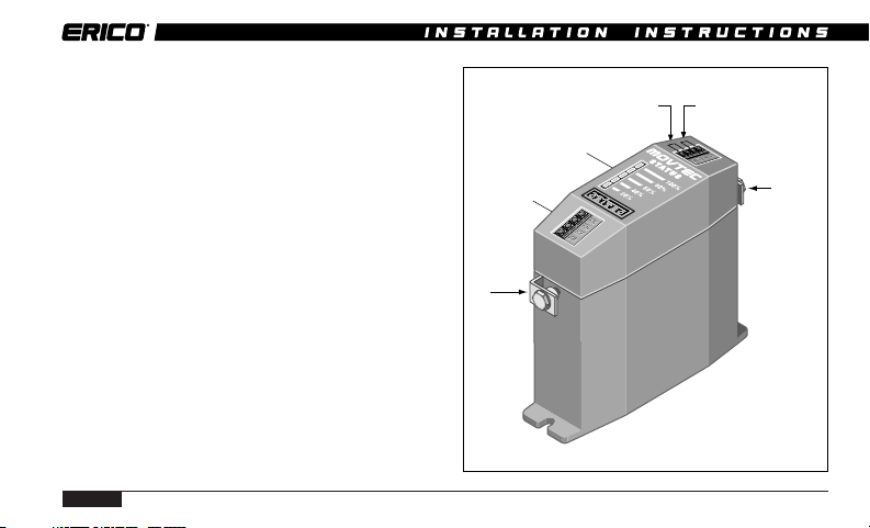
Alarm Contact
Terminals
T2
Terminal
X3-X4 For A-N/A/N-E
configeration option
Status
Indicator
X1-X2 For connection
to optional Mimic Panel
(Ref. Section 15)
SINGLE MODE
MOVTEC
T1
Terminal
Page 7
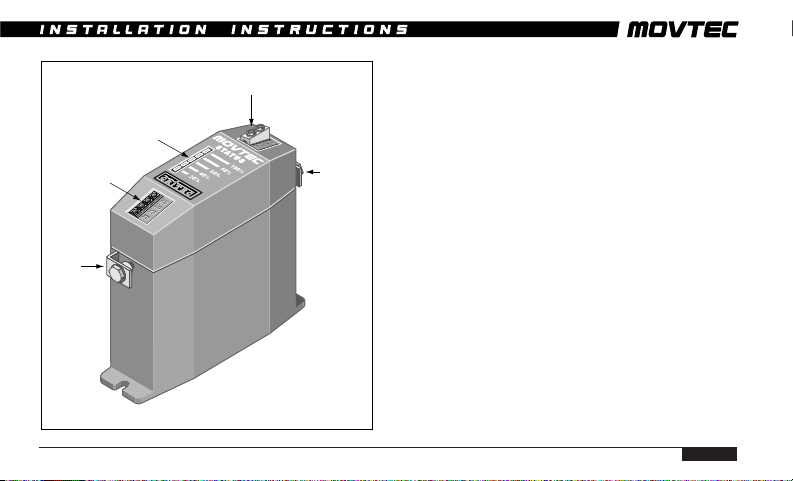
DINLINE INSTALLATION INSTRUCTIONS
Alarm Contact
Terminals
Phase
Terminal
Status
Indicator
Earth Terminal
THREE MODE
MOVTEC
Neutral
Terminal
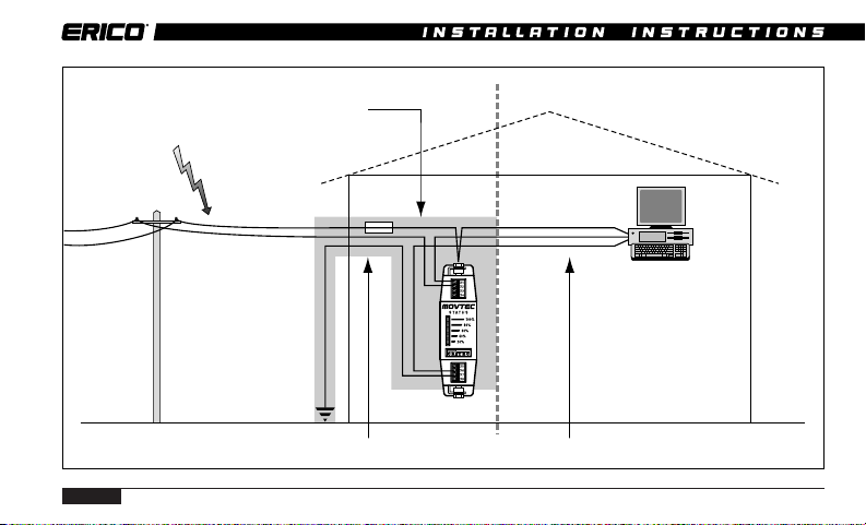
3. PROTECTION CONCEPTS
To optimise effectiveness of installed
protection a concept of “Unprotected” and
“Protected” wiring should be followed.Wiring
from the transient source to the Movtec
should be considered “Unprotected” and kept
remote from all other wiring (approximately
300mm) where possible. Wiring on the
equipment side of the Movtec should be
considered “Protected”.
The separation of “Protected” from
“Unprotected” wiring is recommended in order
to minimise the risk of transients conducted
on “Unprotected” wiring cross coupling on to
“Protected” circuits, thus compromising the
level of protection available from the Movtec.
PAGE 7
Page 8
PAGE 8
GLOBAL LIGHTNING TECHNOLOGIES
Keep other cables and
equipment away
from this area.
Unprotected zone Protected zone
Page 9

DINLINE INSTALLATION INSTRUCTIONS
4. MOUNTING & CAUTIONS
The performance of surge diverters can be
dramatically affected by the method of
connection (refer section 7). Where possible
select a mounting method that allows the
Movtec to be connected in the “Preferred
Connection Method”.
Failure of a Movtec under severe AC overvoltage, such as 11kV on 240V mains, can
result in the generation of significant heat.
Consideration should be given to ensure that
Movtecs are not installed in close proximity to
combustible materials.
Units must be installed in an enclosure or
panel to provide the appropriate degree of
electrical and environmental protection.
Only use enclosures that:
• Do not cause the Movtec temperature to
exceed 60 deg C
• Provide adequate electrical and safety
protection
• Prevent the ingress of moisture and water
• Allow Movtec Status Indication to be
inspected
PAGE 9
Page 10

GLOBAL LIGHTNING TECHNOLOGIES
5 VOLTAGE RATINGS
The TDS (Transient Discriminating
Suppressor) technology has been specifically
developed to cater for abnormal over-voltage
conditions that may occur on sites with poor
voltage regulation, or due to wiring or
distribution faults. The TDS units feature an
extremely high over-voltage withstand to
eliminate heat build up that can occur with
standard technologies when the protection
devices start to clamp on the peak of each
abnormal mains cycle.
Traditional MOV technology (eg MT-275V/
135K/A) is not suitable in applications
where sustained over-voltage conditions
can be experienced.
PAGE 10
Examples of poorly regulated voltage
environments include:
• Smaller power generation supplies
• Sites with large earth currents
• Variable motor speed control circuits
• High harmonic voltage environments (non-
linear loads)
The TDS range of Movtecs with a higher
over-voltage withstand may be able to be
used in these environments following
advice.
Transient protection devices are usually rated
to protect against non-repetitive pulses from
such sources as direct or induced lightning
strikes. They are not designed to provide
protection against repeated cyclic anomalies.
Nor are they designed to provide protection
Page 11

DINLINE INSTALLATION INSTRUCTIONS
Generator Generator
Avoid repetitive voltages in excess of rating
EQUIPMENT
Over-Voltage
Rating
240 Vrms
240 Vrms
Over-Voltage
Rating
Avoid high harmonic voltages
or
MOVTECMOVTECMOVTECMOVTEC
MOVTECMOVTEC
Over-Voltage
Rating
Over-Voltage
Rating
PAGE 11
Page 12

GLOBAL LIGHTNING TECHNOLOGIES
against sustained over-voltage conditions
where the supply voltage exceeds the protection
equipment’s nominal rating for an extended
period of time, ie continuous over-voltages
from poorly regulated generators or
distribution systems.
Smaller power generation equipment
(particularly capacitive excitation induction
generators) does not generally conform to the
same standards of voltage regulation that are
in place for mains power reticulation. A large
number of smaller and/or cheaper generators
have a voltage waveform that is “loosely”
240Vrms (often poorly regulated), but more
importantly, often contains significant higher
order harmonics. These generators may
exhibit a peak voltage on each half cycle far in
excess of the normal 340V. The problem is
usually worse when the generator is lightly
loaded.
PAGE 12
Whilst electrical equipment may tolerate this
over-voltage for a period of time, the clamping
elements in the power protection devices will
begin to conduct on the peak of each 50Hz
cycle, as their voltage threshold is reached
(typically 400V peak for a traditional 275V
diverter). This will cause slow degradation
and ultimate failure of the clamping device
(time dependent upon how poor the waveform
is).
Harmonic voltages may also be present in
distribution systems that do not feature
generators. This is normally where non-linear
loads are used, such as UPSs, rectifiers,
switch mode power supplies and motor speed
controls. The high harmonic voltages in
certain applications may have peak voltages
in excess of the protective clamping voltage
causing problems as described above. Seek the
manufacturer’s advice before installing any
Page 13

DINLINE INSTALLATION INSTRUCTIONS
product into a circuit which features a total
harmonic voltage ratio above 5%.
Model Nominal †Maximum
Voltage Permissible
Abnormal
Over-Voltage
TDS-MT-277 220-277V 480V
TDS-MTU 220-277V 480V
MT275V-135K-A 220-240V 275V
Ensure that the correct voltage rating unit is
installed. Exceeding the nominal rating while
transient events occur may affect product life.
† Note: Other voltage rating Movtecs are available. Refer
to Movtec table for actual ratings.
6. PROTECTION MODES
Movtecs are available in Three Mode and
Single Mode configurations. This refers to how
the internal protection is arranged and
applied to the circuit to be protected.
Three Mode units provide protection between
the Phase-Neutral*, Phase-Earth* and
Neutral-Earth circuit within one Movtec.
Single Mode units provide protection between
two conductors connected to the terminals
marked T1 and T2. These units can be
connected to provide protection from PhaseNeutral* or Phase-Earth* or Neutral-Earth.
To allow the status indication and alarm
circuitry to operate, a neutral connection is
required for Phase-Earth* configured units,
and a Phase* connection is required for
PAGE 13
Page 14

GLOBAL LIGHTNING TECHNOLOGIES
Neutral-Earth configured units. Connection
details for single mode units are detailed on
page 15. Warning - this connection link can be
at mains potential.
* Note. Some users may be used to the
terminology “Active” or “Line”, in place of
“Phase”. For consistency “Phase” is used
throughout this documentation.
Model Modes
TDS-MTU Three Mode
TDS-MT-277 Single Mode
MT275V-135K-A Single Mode
PAGE 14
SINGLE MODE THREE MODE
T1
Terminal
Status
Electronics
T2
Terminal
X4
X3
Neutral
Terminal
Earth
Terminal
Status
Electronics
Phase
Terminal
Page 15

DINLINE INSTALLATION INSTRUCTIONS
SINGLE MODE CONNECTIONS OPTIONS
Ph
T1
T2
N
PHASE
NEUTRAL
PROTECTION
LINK
X3-X4
Ph
T1
X4
T2
N
EE E
PHASE
EARTH
PROTECTION
Ph
N
T1
T2
NEUTRAL
EARTH
PROTECTION
7. CONNECTION METHOD
To optimise transient performance, attempt to
connect the Movtecs in the “Preferred” fashion
as depicted on pages 16 and 17. This is
recommended for cable sizes between 6mm
and 16mm2. Take care not to run the protected
and unprotected wire parallel or in close
proximity.
Where this is not possible due to layout or
X4
conductor size, use the “Non-preferred” “T”
connection method as depicted on pages 16 to
18. With this connection method, the “T” lead
should be between 6mm2 and 16mm2. The
connection should be as short as practicable
(less than 100mm).
Cable sizes less than 6mm2 should not be used
without specialist advice.
2
PAGE 15
Page 16

GLOBAL LIGHTNING TECHNOLOGIES
PREFERRED CONNECTION METHOD
CORRECT
Separate wires
PAGE 16
INCORRECT
NON-PREFERRED "T" CONNECTION METHOD
Keep
Short
Keep Close
Keep
Short
Page 17

DINLINE INSTALLATION INSTRUCTIONS
PREFERRED CONNECTION METHOD EXAMPLES
NEUTRAL
EARTH
LINE LOAD
SINGLE MODE UNITS
LINE LOAD
PHASE
THREE MODE UNITS
PAGE 17
Page 18

GLOBAL LIGHTNING TECHNOLOGIES
NON-PREFERRED "T" CONNECTION METHOD EXAMPLES
NEUTRAL
2
6-16 mm
The inductance of
branch connections
increases the clamp
voltages seen by
the load.
LINE LOAD LINE LOAD
EARTH
PHASE
PAGE 18
SINGLE MODE UNITS
THREE MODE UNITS
Page 19

DINLINE INSTALLATION INSTRUCTIONS
CORRECT
RCD
ELCB
Protected
Equipment
RCD
ELCB
INCORRECT
PAGE 19
Page 20

GLOBAL LIGHTNING TECHNOLOGIES
8. RCD, ELCB
Where RCDs/ELCBs (Residual Current
Devices / Earth Leakage Circuit Breakers) are
fitted the Movtecs should be installed in the
circuit prior to these devices (ie upstream).
Where this can not be avoided and RCDs/
ELCBs are installed upstream, nuisance
tripping of the RCD/ELCB may occur during
transient activity.
Contact your local ERICO agent for advice if
upstream RCDs/ELCBs can not be avoided.
PAGE 20
9. ISOLATION AND FUSING
Overcurrent and short circuit protection must
be provided to protect the Movtec and
associated wiring if a fault develops. The
overcurrent protection should be installed in
such a manner to also provide a means of
isolating the Movtec module from the mains
supply. This is an important safety
consideration and is required in the event that
any future maintenance or testing is needed.
The Movtec uses disconnection devices to
isolate internal segments that have reached
the end of their service life. In order for this
disconnection to occur correctly, Movtecs
should be only used on circuits with fuse or
circuit breaker ratings of 32A or greater.
(Nuisance operation of the overcurrent
protection may occur during transient activity
on smaller capacity circuits.)
Page 21

DINLINE INSTALLATION INSTRUCTIONS
Ph
Supply
N
OVERCURRENT PROTECTION
F1 >100A
Install F2 when F1 exceeds 100A
*HRC - High Rupture Capacity
F2 =100A HRC*
Equipment to
be protected
Ph
N
OVERCURRENT PROTECTION
Ph
F1 >100A
Upstream Fuse
Supply
N
Suitable connection method when upstream
Fuse/Supply capacity does not exceed 100A
Ph
Equipment to
be protected
N
PAGE 21
Page 22

GLOBAL LIGHTNING TECHNOLOGIES
On circuits with a capacity of greater than
100A, the Movtecs should be installed in
series with a 100A HRC fuse being placed
prior to the Movtec, as detailed in the diagram
on page 21. This will require the Movtec to be
installed in a similar manner to the nonpreferred “T” connection method. Care must
be taken to keep “T” connections as short and
straight as possible. Note that this fuse may
rupture under surge events exceeding 60kA,
thereby disconnecting the protection circuit.
Under such conditions it is important that
suitable monitoring of the alarm contact
should be carried out to detect this possible
occurrence.
PAGE 22
10. STATUS INDICATION AND
ALARMS
A characteristic of all transient and surge
protection devices is that they degrade in
proportion to the magnitude and number of
incident surges to which they have been
subjected. Status indication should be
periodically monitored to determine if
replacement is required.
Each Movtec features 5 protection segments.
The status for each of these sectors is
provided by way of a 5 segment LED bar
graph. If any sector is damaged due to excess
surge activity, a LED will extinguish. The
LEDs extinguish in a sequential order (100%
LED out first, 80% LED out next etc.)
irrespective of which sector has sustained
damage.
Page 23

DINLINE INSTALLATION INSTRUCTIONS
When mains voltage is applied to the fully
functional Movtec, the alarm contacts will be
closed. Should the surge handling capacity
fall to below the alarm threshold, these
contacts will open. The contacts are “fail-safe”
in that, if power to the unit fails, the contacts
will also revert to the open condition.
For Single Mode units (TDS-MT-277 and
MT275V-135K-A)
• The voltage free alarm contacts are activated
(opened) as soon as the primary protection
status displays 60% or less and indicates
that the Movtec unit should be replaced.
For Three Mode units (TDS-MTU)
• The voltage-free alarm contacts are activated
(opened) as soon as the protection status
displays 80% or less. This indicates that
damage has been sustained to the protection
of one of the three modes and that the TDSMovtec unit should be replaced.
MOVTEC MODEL TERMINALS ALARM OPERATES
WHEN
TDS-MT-277 X5 & X7 MOVTEC displayed
capacity =< 60%
MT275V-135K-A X5 & X7 MOVTEC displayed
capacity = <60%
TDS-MTU X5 & X7 MOVTEC displayed
capacity = <80%
Contact Rating 250Vac, 10A resistive, 1A inductive
Contact connection Multi-stranded wire with CSA not
greater than 1.5mm
2
Where multiple Movtecs are used, such as in
three phase distribution systems the alarm
contacts may simply be connected in series to
provide a common alarm output connection.
PAGE 23
Page 24

GLOBAL LIGHTNING TECHNOLOGIES
11. MPM, MOVTEC PROTECTION
MODULE
The MPM utilises a high energy Neutral to
Earth spark gap to provide robust protection
against earth potential rise problems. Care is
required to ensure co-ordination of this device
MPM
Supply Equipment to
PREFERRED CONNECTION METHOD
PAGE 24
be protected
Supply Equipment to
NON PREFERRED
"T" CONNECTION METHOD
if any other voltage limiting device is
connected either upstream or downstream in
the Neutral to Earth circuit. Contact your
local agent for further information if
other N-E protection devices are
installed and co-ordination may be
affected.
MPM
(Refer section 7)
be protected
Supply Equipment to
CONNECTION METHOD ON
CIRCUITS GREATER THAN 100A
MPM
100A HRC Fuses
in phase lines
be protected
Page 25

DINLINE INSTALLATION INSTRUCTIONS
INSTALLATION PROCEDURE FOR MPM
1. Remove the cover from the MPM.
2. Select the MPM mounting position to ensure
optimum electrical connection method (refer
Section 7) and in accordance with all given
instructions.
3. Position and mark the mounting position of
the MPM on the wall.
4. Depending on the mounting surface, prepare
suitable anchoring holes for the marked
position.
5. Snap the mounting spacers, supplied, into
the rear of the back of the MPM as shown
in Figure 1. (see inside back cover P31)
6. Mount the unit to the wall. To ensure the
IP33 rating is preserved, the MPM should
be mounted to the wall using the spacers
provided and one of the fixing methods as
shown in Figure 1. (see inside back cover P31)
7. Prepare the appropriate cable glands. It is
recommended that a nylon cable gland
(typically rated at IP66) be used.
8. Install wiring, taking care to support cabling
directly connecting to the MPM unit, and
tighten all terminals.
9. Check that the MPM is installed in accordance with all instructions, and relevant
electrical safety codes.
10.Replace MPM cover, then apply power.
11.Correct operation of the MPM unit is established by checking that all 5 LED’s on each
MOVTEC bar graph are lit, and that power
is correctly being supplied to the load(s).
INSTALLATION ARRANGEMENT FOR
AUSTRALIAN MEN SYSTEMS
Under Australian Standards classification,
MPMs are considered a piece of equipment to
PAGE 25
Page 26

be connected to the mains
supply. The MPMs are not
intended for use as, nor are
they, a ‘switch
board’,
‘distribution board’ or other
equipment. As MPMs are
classified as ‘electrical
equipment’ (ie: a product),
AS 3000 Wiring Regulations
apply to the installation and
operation of the units.
In the multiple earth
neutral (MEN) distribution
system, the MPM equipment
should be installed as clos e
as possible after the MEN
point and after both the
main disconnect switch/
overcurrent protector and
any metering equipment.
PAGE 26
GLOBAL LIGHTNING TECHNOLOGIES
TYPICAL CONNECTION DETAIL FOR MPM POINT-OF-ENTRY INSTALLATION
IN MEN DISTRIBUTION SYSTEM
NEUTRAL
EARTH
1
2
3
METERING
MAIN
DISTRIBUTION
M.E.N.
LINK
MPM
SUB
DISTRIBUTION
Page 27

DINLINE INSTALLATION INSTRUCTIONS
12. MAINTENANCE & TESTING
Before removing any unit from service
ensure that power to the device is
isolated. Replacement of any Movtec
units should only be undertaken in
accordance with all relevant Electricity
and Safety Standards by suitably
qualified personnel.
Movtecs should be inspected periodically, and
also following any periods of lightning or
transient activity. Check the status indicators
and replace if in the “Alarm” condition as
detailed in Section 10 -STATUS INDICATION.
For high transient exposure sites or those of a
critical operational nature, it is recommended
that the alarm outputs be monitored to
provide an additional warning of reduced
capacity (refer Section 10).
Movtecs are designed for optimum
performance under severe transient activity.
To provide this performance, electronic
components in the Movtec are encased in a
patented proprietary, shock and thermal
absorbant compound. Units cannot be
serviced, they must be replaced.
Do not attempt to open or tamper with the
units in any way as this may compromise
performance and will void warranty.
Do not “Megger” or perform other types of
electrical tests that apply voltages greater
than the nominal operating voltage of the
Movtec. The Movtec will attempt to limit these
voltages thereby affecting the test result.
Where these tests must be performed, remove
the Movtec from circuit first.
PAGE 27
Page 28

GLOBAL LIGHTNING TECHNOLOGIES
13. EXTENDED WARRANTY
This product has a limited warranty to be free
from defects in materials and workmanship for a
period of five (5) years from the date of dispatch
from the Manufacturer. The Purchaser
acknowledges that lightning is a natural event
with statistical variation in behaviour and energy
levels which may exceed product ratings, and 100 %
protection is not offered and cannot be provided
for. Therefore the Manufacturer’s liability is
limited to the repair or replacement of the product
(at the Manufacturer’s sole option) which in its
judgement has not been abused, misused,
interfered with by any person not authorised by
the Manufacturer, or exposed to energy or
transient levels exceeding the Manufacturer’s
specifications for the product. The product must
be installed and earthed (where applicable) in
strict accordance with the Manufacturer’s
specifications and all relevant national Electricity
and Safety Standards. The Manufacturer and the
PAGE 28
Purchaser mutually acknowledge that the
product, by its nature, may be subject to
degradation as a consequence of the number and
severity of surges and transients that it
experiences in normal use, and that this warranty
excludes such gradual or sudden degradation.
This warranty does not indemnify the Purchaser
of the product for any consequential claim for
damages or loss of operations or service or profits.
Customers should contact their nearest
manufacturer’s agent to obtain a Product Repair
Authorisation Number prior to making any claim
under this warranty. This is only a summary of
the warranty given by the Manufacturer. The full
text of the warranty is set out in the
Manufacturer’s Conditions of Quotation and Sale.
The above limited warranty is additional to rights
which arise in respect of the sale of industrial and
technical products and services to knowledgable
buyers under the Australian Trade Practices Act
1974 as amended.
Page 29

DINLINE INSTALLATION INSTRUCTIONS
14. SIX POINT PLAN
Critec Movtec surge diverters form an
important part of the much larger ERICO
lightning, surge and transient protection
philosophy (ERICO Lightning Technologies
“Six Point Plan”). The level of protection and
the degree of attention dedicated to each of
the six points will require careful
consideration for each site. The degree of
protection required is determined by the
individual site location/exposure with the aid
of risk management principals.
For further advice on your protection needs
please contact your local representative.
Capture the
lightning strike
Conduct the strike
to ground safely
Dissipate the energy
through a low
impedance earth
system
Eliminate earth
loops and
differentials
Protect equipment
from surges on
power lines
Protect equipment
from transients on
telecommunication
and signal lines
PAGE 29
Page 30

15. USE OF MIMIC PANELS
Movtecs are used in the Proline range of
Surge Reduction Filters where superior
protection is required for critical or sensitive
electronic equipment. Some models of SRF use
an electronic mimic panel to display in the
M
OVTEC
& M
front door the status of the internal Movtecs.
The X1-X4 terminals on the Movtec are used
for this purpose. If this Movtec is to be used
with a mimic panel (possibly as a replacement
for an existing Movtec in a SRF) please ensure
compatibility as below.
IMIC COMPATIBILITY
Movtec Version Mimic Version
TDS-Mimic Hybrid Mimic Discrete Mimic
#300732 #300731 #300730
EA-SRFP-117 EA-SRFP-115 EA-SRFP-104
EA-117 EA-115 EA-104
TDS-MT-277 Yes Note 1 No
MT-275V/135K/A #300867 Yes Yes Note 2
MT-275V/135K/A #300865/300866 Yes Yes Yes
Note 1 Mimic will operate for supply voltages up to 275Vrms
Note 2 Request Product Update 44 for further details
PAGE 30
Page 31

Figure 1. MPM mounting spacers.
Page 32

SINGLE MODE CONNECTIONS OPTIONS
Ph
T1
LINK
X3-X4
Ph
T1
X4
Ph
N
E
www.erico.com
T2
PHASE
NEUTRAL
PROTECTION
T2
N
E
PHASE
EARTH
PROTECTION
N
T1
X4
T2
E
NEUTRAL
EARTH
PROTECTION
 Loading...