

Page 1
SURGE SUPPRESSOR
Handbook No:
HB-HBCR-109
© Copyright
INSTALLATION INSTRUCTIONS
Includes TDS-AR Alarm Relay
and TDS-SC Surge Counter
www.erico.com
ISSUE: 3 April 2003
Page 2

INSIDE FRONT COVER
(Blank)
Page 3

CONTENTS
Page
Page
1. Warnings ... ... ... ... ... ... ... ... ... ... ... 4
2. Introduction ... ... ... ... ... ... ... ... ... ... 5
3. Quick Installation Guide ... ... ... ... ... ... 5
4. Protection Concepts .. ... ... ... ... ... ... ... 6
5. Mounting ... ... ... ... ... ... ... ... ... ... ... 7
6. Voltage Ratings ... ... ... ... ... ... ... ... ... 8
7. Protection Modes .. ... ... ... ... ... ... ... ... 8
8. Conductor Sizes ... ... ... ... ... ... ... ... ... 10
9. Conductor Length ... ... ... ... ... ... ... ... 11
10. RCD, ELCB ... ... ... ... ... ... ... ... ... ... 14
11. Isolation and Fusing .. ... ... ... ... ... ... 15
12. Status Indication ... ... ... ... ... ... ... ... 17
13. Maintenance & Testing .. ... ... ... ... ... 18
14. Alarm Relay (TDS-AR) .. ... ... ... ... ... 19
15. Surge Counter (TDS-SC) ... ... ... ... ... 26
16. Typical Domestic Installation ... ... ... 29
17. Extended Warranty ... ... ... ... ... ... ... 30
18. Six Point Plan ... ... ... ... ... ... ... ... ... 31
PAGE 3
Page 4
DSD INSTALLATION INSTRUCTIONS
1. WARNINGS
• Prior to installation ensure that the unit is
of the correct voltage and frequency, and is
the type recommended for the local power
distribution, and for the equipment being
protected.
• Hazardous voltages may exist internally to
the modules. The units should be installed
(and replaced) only by qualified personnel
in accordance with all relevant Electricity
Safety Standards.
• Do not power three phase connected units
without the upstream neutral connected.
Failure to do so may damage the units and/
or the load.
• Where the unit has an earth terminal, this
must be connected to a low impedance earth
(<10 Ω) for correct operation.
PAGE 4
• If connecting to the TDS Opto-coupler
alarm outputs do not reverse the +/connections or exceed the maximum
permissible ratings as damage may occur.
• Use only the TDS-AR Alarm Relay with
TDS-DINLINE.
• Use only TDS-SC Surge Counter with TDS
DINLINE.
• Units must be installed in an enclosure or
panel, ensure this does not cause the units
environmental ratings to be exceeded.
• Do not “Megger” or “Flash Test” circuits
with TDS-DINLINE units installed.
• All instructions must be followed to ensure
correct and safe operation.
• Diagrams are illustrative only, and should
not be relied on in isolation.
Page 5
2. INTRODUCTION
This Installation Manual details the preferred
procedure for the installation of TDSDINLINE™ SURGE SUPPRESSORS and
options.
The TDS-DINLINE SURGE SUPPRESSORS
are available in a variety of surge ratings,
which are packaged in the 2M, 4M and 8M
“DIN 43 880” compliant enclosures. They are
designed to suit many distribution systems
including TN-C, TN-S, TN-C-S (MEN) and TT.
They can be selected for use with distribution
systems with nominal RMS voltages of 110/
120, 220/230/240V or 277V at frequencies of
50/60 Hz.
Recommended installation and connection of
the ALARM RELAY (TDS-AR) is detailed in
Section 14. Installation and connection of the
Surge Counter (TDS-SC) is detailed in section
15.
3. QUICK INSTALLATION GUIDE
Install in the following manner:
1. Ensure that power is removed from the area
and circuits to be connected.
2. Install the DIN mounting rail, if not fitted.
3. Snap lock the Surge Suppressor to the rail.
4. Connect wiring to the indicated terminals.
5. Ensure compliance with supplied
instructions.
6. Apply power and observe correct operation
of Status Indicators, and alarm facilities if
utilised.
PAGE 5
Page 6
DSD INSTALLATION INSTRUCTIONS
4. PROTECTION CONCEPTS
To optimise effectiveness of installed
protection a concept of “Unprotected” and
“Protected” wiring should be followed. Wiring
from the transient source to the Surge
Suppressor should be considered
“Unprotected” and kept remote from all other
wiring (approximately 300mm) where possible.
Wiring on the equipment side of the Surge
Suppressor should be considered “Protected”.
The separation of “Protected” from
“Unprotected” wiring is recommended in order
to minimise the risk of transients conducted on
“Unprotected” wiring cross coupling on to
“Protected” circuits, thus compromising the
level of protection available from the Surge
Suppressor.
PAGE 6
Keep other cables and
equipment away
from this area.
Unprotected zone Protected zone
Page 7
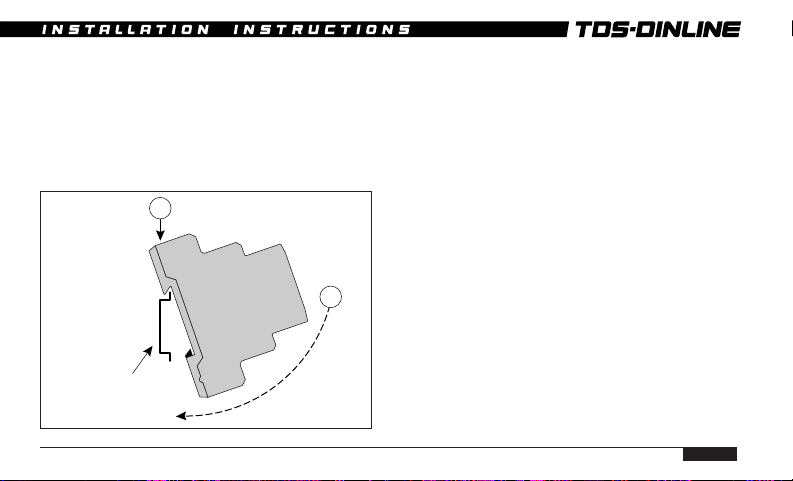
5. MOUNTING
Surge Suppressors are designed to clip to
35mm top hat DIN rails (to Standard
EN50022). Unless otherwise mechanically
restrained, use horizontal DIN rails with the
Surge Suppressor fixing clip to the bottom, ie
label text the correct way up.
Units must be installed in an enclosure or
panel to provide the appropriate degree of
electrical and environmental protection.
35 mm DIN rail
(EN50022)
1
Only use enclosures that:
• Do not cause the internal temperature to
exceed 55 deg C.
• Provide adequate electrical and safety
2
protection.
• Prevent the ingress of moisture and water.
• Allow Surge Suppressor Status Indication
to be inspected.
PAGE 7
Page 8
DSD INSTALLATION INSTRUCTIONS
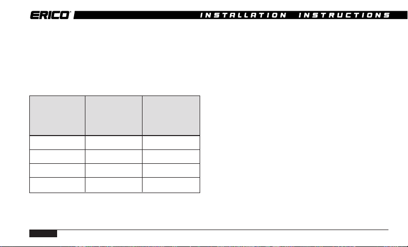
6. VOLTAGE RATINGS
Ensure that the correct voltage rating unit is
installed. Exceeding the nominal voltage
rating under transient conditions may affect
product life. Do not exceed the Maximum
Permissible Abnormal Over Voltage rating.
Model Nominal Voltage Permissible
TDS XXX-120 110-120 Vac 240Vac
TDS XXX-208 208 Vac 260 Vac
TDS XXX-240 220-240 Vac 415 Vac
TDS XXX-277 220-277 Vac 480 Vac
PAGE 8
Maximum
Abnormal
Over Voltage
7. PROTECTION MODES
Protection Modes refers to how the internal
protection is arranged and applied to the
circuit to be protected.
TDS-DINLINE Surge Suppressors are Single
Mode units which provide protection between
two conductors connected to the terminals
marked T1 and T2. These units can be
connected to provide protection from PhaseNeutral* or Phase-Earth* or Neutral-Earth.
To allow the status indication and alarm
circuitry to operate, a neutral connection is
required for Phase-Earth* configured units,
and a Phase* connection is required for
Neutral-Earth configured units.
* Note. Some users may be used to the
terminology “Active” or “Line”, in place of
“Phase”. For consistency “Phase” is used
throughout this documentation.
Page 9
SINGLE MODE UNITS
CONNECTION OPTIONS
Protection
T1
T2
X
Status
Electronics
Ph-E ProtectionPh-N Protection N-E Protection Ph-Ph Protection
Ph
NPh
E
Ph N
T1 T2 XT1 T2 X
PROTECTION MODE
Terminals Ph-N Ph-E N-E Ph
T1 Ph E E Ph
T2 NPhNPh
X PhNPhPh
NPh
E
T1 T2 X
Ph
x
T1 T2 X
PhyPh
x - Phy
PAGE 9
x
x
y
x
Page 10
DSD INSTALLATION INSTRUCTIONS
Phase to Phase protection can also be provided
by Surge Suppressors, provided that the
nominal and maximum voltage ratings are not
exceeded.
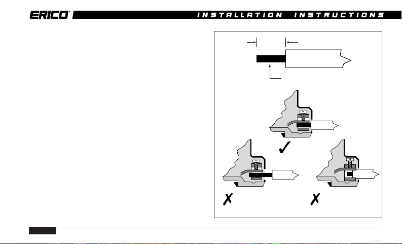
8. CONDUCTOR SIZES
Each Surge Suppressor terminal is designed
to accept wire sizes from 1.5mm2 to 6mm2,
solid or stranded conductor. Insulation should
be stripped back 8mm before terminating into
the tunnel terminal.
Where two conductors require termination in
the same tunnel terminal, conductors should
be limited to a maximum size of 4mm2.
Do not use excessive force when tightening the
terminal.
PAGE 10
8mm
Insulation cut
back too far
1.5-6 mm
Correct
2
conductor
Insulation not cut
back far enough
Page 11

9 CONDUCTOR LENGTH
To optimise transient performance, attempt to
connect units in the “Preferred” fashion as
depicted on pages 11 and 12. Some units have
double terminals to facilitate this. Take care
not to run parallel “protected” and
“unprotected” wiring.
Where this is not possible due to layout or
conductor sizing, use the “Non-preferred” “T”
connection method as depicted on page 13. With
this connection method, the “T” lead length
should be kept as short as practicable (less than
100mm) and wires should be bundled together.
The “T” conductor should be equal in size to the
main conductor, up to a maximum of 6mm2.
PREFERRED CONNECTION METHOD
Separate wires
Ph Ph Ph
Ph
Ph Ph
CORRECT
INCORRECT
NON-PREFERRED CONNECTION METHOD
Keep
Short
Keep Close
T1 T2
T1 T2
CORRECT
INCORRECT
PAGE 11
Page 12

Supply
Ph
N
E
DSD INSTALLATION INSTRUCTIONS
PREFERRED CONNECTION METHOD EXAMPLE FOR Ph-E PROTECTION
Supply
Ph
N
E
Maximum
conductor
size 6mm
T2T
T
1T1
X
2
Maximum
2
conductor
size 2x4 mm
or 1x6 mm
T2T1X
Protected
Equipment
Maximum
conductor
size 4mm
2
Protected
Equipment
2
2
PAGE 12
TD140-2S
TDS1160-8S
Page 13

Supply
Ph
N
E
Bundle
together
NON-PREFERRED "T" CONNECTION METHOD EXAMPLE FOR Ph-E PROTECTION
Supply
Protected
Equipment
Keep as short
as practical
Ph
N
E
Bundle
together
Protected
Equipment
Keep as short
as practical
T2T1X T2T
2
Maximum
conductor
size 6mm
Maximum
conductor
size 6mm
TDS 140-2S
T1T
1
2
TDS1160-8S
X
2
PAGE 13
Page 14

DSD INSTALLATION INSTRUCTIONS
10. RCD, ELCB
Where RCDs/ELCBs (Residual Current
Devices / Earth Leakage Circuit Breakers) are
fitted the Surge Suppressor units should be
installed in the circuit prior to these devices
RCD
ELCB
Protected
Equipment
CORRECT
PAGE 14
(ie upstream). Where this can not be avoided
and RCDs/ELCBs are installed upstream,
nuisance tripping of the RCD/ELCB may occur
during transient activity.
Contact your local representative for advice if
upstream RCDs/ELCBs can not be avoided.
RCD
ELCB
PhPh
INCORRECT
Page 15

11. ISOLATION AND FUSING
Overcurrent and short circuit protection must
be provided to protect the Surge Suppressor
and associated wiring if a fault develops. The
overcurrent protection should be installed in
such a manner to also provide a means of
isolating the TDS-DINLINE module from the
mains supply. This is an important safety
consideration and is required in the event that
any future maintenance or testing is needed.
For Surge Suppressors installed in the
“preferred” connection method (page 12),
upstream overcurrent protection should be
installed based on the maximum current
carrying capacity of the conductors.
Australian regulations AS3000-1991, Table B2
specifies the following upstream protection for
the protection of single phase circuits.
A mm
Ph
2
A mm
Ph Ph
2
Conductor Size Required Fuse
2
CB or Fuse Rewirable Fuse
A mm
2
1.5 mm
2
2.5 mm
2
4.0 mm
2
6.0 mm
Fuse selection based on maximum current carrying capacity of
conductor. Smaller rated fuse may be selected if required.
CB = Circuit Breaker.
16A 12A
20A 16A
25A 20A
32A 25A
PAGE 15
Page 16

DSD INSTALLATION INSTRUCTIONS
For Surge Suppressors installed in the “nonpreferred” connection method (page 13),
depending upon the size and fusing in the
main circuit, the “T” connection may require
independent fusing to be installed.
Circuits with upstream protection rated at
greater than 100A must have a 100A HRC
fuse or circuit breaker installed in the T
connection as detailed by the following
diagram.
Warning:
Isolation/fusing installed in the “T” connection
may disconnect the Surge Suppressor from the
circuit/equipment to be protected. The remote
alarm contacts of the ALARM RELAY (TDSAR) should be used to detect this occurrence.
Operation of the isolation/fuse will remove the
protection from the circuit.
PAGE 16
Supply
A
A mm
2
B
B mm
2
Ph
Supply Upstream* T-Connection Required
Conductor Protection Size T-Connection
Size Fuse
2
A fuse rating B mm2 B fuse rating
A mm
2
1.5 mm
2.5 mm
4.0 mm
6.0 mm
>6.0 mm
>6 mm
* Fuse rating A selection based on maximum current carrying capacity of
conductor. Smaller rating fuse may be selected ir required.
** Short circuit protection selection based on I
16A 1.5 - 6 mm2Nil
2
20A 2.5 - 6 mm2Nil
2
25A 4 - 6 mm
2
32A 6 mm
2
<100A 6 mm
2
>100A 6 mm
2
2
2
2
t rating of cable and fuse.
2
Nil
Nil
Nil**
100 A**
Page 17

The selection of the 100A HRC fuse is not
based on the load carrying capacity of the
main circuit but the “T” connection I2t rating.
The “T” connection under normal conditions
does not carry the load current. Only under
surge or fault conditions does this connection
carry large currents. Under Australian
Standard AS3008.1-1989 it is permissible to
rate the protection for these types of circuits
by the I2t ratings of the cable. For installation
of Surge Suppressor in countries not covered
by these regulations it is recommended that
this practice be followed, unless it conflicts
with the compliance of the local regulations.
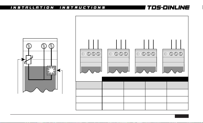
12. STATUS INDICATION
A characteristic of all transient and surge
protection devices is that they degrade in
proportion to the magnitude and number of
incident surges to which they have been
subjected. Status indication should be
periodically monitored to determine if
replacement is required.
2S units
These units are identified by the single Status
Indicator provided on the front panel. When
power is applied and full surge capacity is
available the Status Indicator will be
illuminated. Should the indicator fail to
illuminate the Surge Suppressor should be
replaced, as optimum protection is no longer
provided. Note: The Status Indicator will not
operate (regardless of surge capacity) if power
is not available.
4S units
These units are identified by two Status
Indicators which are provided on the front
panel. These Status Indicators monitor
PAGE 17
Page 18

DSD INSTALLATION INSTRUCTIONS
separate protection segments. Each Status
Indicator is illuminated when power is
available and when full surge capacity is
available by that segment. The Surge
Suppressor should be replaced if either
Status Indicator fails to illuminate. Note: The
Status Indicators will not operate (regardless
of surge capacity) if power is not available.
8S units
These units are identified by four Status
Indicators which operate similar to above. The
Surge Suppressor should be replaced if any
two or more Status Indicators fail to
illuminate.
PAGE 18
13. MAINTENANCE & TESTING
Before removing any unit from service
ensure that power to the device is
isolated. Replacement of any Surge
Suppressor should only be undertaken in
accordance with all relevant Electricity
and Safety Standards by suitably
qualified personnel.
TDS-DINLINE units should be inspected
periodically, and also following any periods of
lightning or transient activity. Check the
status indicators and replace if recommended
in Section 12 -STATUS INDICATION.
For high transient exposure sites or those of a
critical operational nature, it is recommended
that the alarm outputs be monitored to
provide an additional warning of reduced
capacity (refer Section 14 - ALARM RELAYTDS-AR).
Page 19

TDS-DINLINE Surge Suppressor units are
designed for optimum performance under
severe transient activity. To provide this
performance, electronic components in the
unit are encased in a patented proprietary,
shock and thermal absorbent compound.
Units cannot be serviced, they must be
replaced.
Do not attempt to open or tamper with the
units in any way as this may compromise
performance and will void warranty.
Do not “Megger” or perform other types of
electrical tests that apply voltages greater
than the nominal operating voltage of the
Surge Suppressor. The Suppressor will
attempt to limit these voltages thereby
affecting the test result. Where these tests
must be performed, remove the Surge
Suppressor from circuit first.
14. ALARM RELAY (TDS-AR)
The Surge Suppressor status monitoring
circuit which provides the visual status
display also provides a low voltage optocoupler alarm output circuit. This should only
be connected to the TDS ALARM RELAY. The
TDS-AR voltage free alarm contacts may then
provide output to external alarm systems or
remote monitoring circuits.
The TDS ALARM RELAY provides fully
isolated potential free change-over alarm
output contacts. One TDS-AR can be used per
Suppressor opto-coupler alarm or Multiple
Suppressor opto-coupler alarms can be
connected in series to the one TDS-AR to
provide a common output.
PAGE 19
Page 20

DSD INSTALLATION INSTRUCTIONS
1 x TDS-AR supports:
20 x TDS140-2S
or 10 x TDS 180-4S
or 5 x TDS 1160-8S
or relative combinations.
It is recommended that the TDS-AR unit be
powered from the same power circuit that
feeds to the Surge Suppressor being
monitored, however it can be powered from
other circuits. This allows for example, one
TDS-AR unit to be connected to separate
Surge Suppressors that are protecting a three
phase circuit.
To satisfy Australian wiring regulations the
phase supply to the TDS-AR needs to be
protected by an overcurrent fuse/circuit
breaker. The overcurrent protection should be
selected according to the wiring size
PAGE 20
connecting to the TDS-AR Phase and Neutral
terminals. For reference a table of values is
given on page 24.
Note. Depending upon the usage of the TDSAR output contacts, failure of power to the
TDS-AR may be interpreted as a failure of one
or more Surge Suppressors. Visual inspection
of all units Status displays would determine
this.
Page 21

STATUS
Protection Operational
Protection Alarm
Fault Mode
DISPLAY
EXPLANATION
Normal
16
Fault
12
14
Normal operation
Normal (green) indicator ON
Red indicator OFF
Relay is energised
Power is supplied
Normal
Normal
16
Fault
12
Fault
14
Surge Suppressor in alarm mode
or power to Suppressor has been
removed
Normal (green) indicator OFF
Red indicator ON
Relay is de-energised
Power is supplied
Power to TDS-AR removed
Protection status unknown
Normal (green) indicator OFF
Red indicator OFF
Relay is de-energised
Power is OFF
16
12
14
PAGE 21
Page 22

Ph
DSD INSTALLATION INSTRUCTIONS
SINGLE ALARM CONNECTION EXAMPLE
To transient
N
E
protected
equipment
TDS140-2S
PAGE 22
T2T1X
NL
TDS-AR
✽
Opto-coupler output
✽
✽
WARNING - Connections are polarity sensitive. Do not reverse.
Voltage free contacts
To remote
alarm
circuit
Page 23

MULTIPLE ALARM CONNECTION EXAMPLE
T1T
1
T2T2X
X
T
2T1
✽✽
TDS180-4S TDS140-2S
✽
WARNING - Connections are polarity sensitive. Do not reverse.
NL
TDS-AR
Voltage free contacts
✽
To remote
alarm
circuit
PAGE 23
Page 24

DSD INSTALLATION INSTRUCTIONS
TDS-AR SPECIFICATIONS:
Output Contact Ratings
Nominal switching capacity
Maximum switching power
Maximum switching voltage
Maximum switching current
Input to output isolation
Note: TDS-AR operates on supply voltages
of 100-480V Vrms.
TDS-AR OVERCURRENT PROTECTION
The power supply to the TDS-AR circuit must
be provided with upstream overcurrent
protection. The fuse rating should be based on
PAGE 24
2A 30VDC
60W 125VA
220VDC, 250VAC
2A
4kV
the wiring size used to connect to the TDS-AR
Ph & N terminals.
Australian regulations AS3000-1991, Table B2
specifies the following upstream protection for
single phase circuits, unenclosed in air.
Cable Size HRC Fuse or CB Rewirable Fuse
2
1.5mm
2.5mm
4mm
6mm
16A 12A
2
20A 16A
2
25A 20A
2
32A 25A
Where overcurrent protection of the
appropriate rating or smaller is already fitted
in the upstream circuit, overcurrent protection
at the TDS-AR will not be required.
Page 25

ALARM TESTING
Testing of the Alarm Relay which is connected
to a fully functional Surge Suppressor unit
can be accomplished by removing power to the
Surge Suppressor only. The Alarm Relay
Status indication and output contacts should
alter from the Normal to Fault condition.
Testing of the Alarm Relay unit alone may be
accomplished by disconnecting the + / connections to the unit. When power is applied
the “Fault” Status Indicator should be
illuminated. By connecting the + / - terminals
together, the “Normal” Status Indicator should
be illuminated. The output contacts should
alter to the appropriate state.
USE OF OTHER INTERFACES
Only ERICO TDS-AR units are recommended
for the interfacing of equipment to the TDSDINLINE opto-coupler alarm output circuit.
The direct connection of other equipment to the
opto-coupler alarm output circuit may not
provide sufficient isolation or exceed the optocoupler specifications. This may damage the
Surge Suppressor and/or the connected
equipment. Warranty may be voided under such
circumstances.
SURGE SUPPRESSOR OPTO-COUPLER ALARM
Opto-coupler
Optocoupler
Protection
diode
Vce = 30V DC
Ic = 150 mA
Note: TDS XXX-4S and
TDS XXX-8S have
respectively 2 and 4
opto-couples connected
internally in series.
PAGE 25
Page 26

DSD INSTALLATION INSTRUCTIONS
15. TDS-SC SURGE COUNTER
The Surge Counter is designed to interface to
the TDS DINLINE units via the supplied CT,
to record the number of surges and impulses
diverted. This is achieved by measuring the
transient current diverted by the TDS
protection device. It is important that the CT
be installed into the circuit where it is
measuring the surge current only, and not
where mains load current is passed through
the core. Method 1 and Method 2 (page 28)
detail the correct connection. Page 27 shows
an incorrect connection as the equipment load
current is passed through the CT core. The
magnetic field from the load carrying
conductor may cause the CT core to saturate.
The surge Counter may fail to record any
transients and additionally dangerously high
voltages may be present on the TDS-SC & CT
terminals.
PAGE 26
WARNINGS
• Do not install CT into load current carrying
circuits.
• CT must be installed into surge current
path only.
• Only install the CT and Surge Counter after
all power and transient sources are
removed and isolated from the equipment
the Surge Counter is to monitor.
• Do not open circuit or disconnect
connections on the secondary of the CT
when monitored circuit is powered or
connected to possible transient source.
Hazardous voltages may exist in the
secondary circuit and in the CT/TDS-SC if
these instructions are not followed.
Page 27

• Only this CT should be used with the TDSSC Surge Counter, other suppliers devices
may not operate correctly or pose a safety
hazard.
• These instructions should only be carried
out by qualified personnel in accordance
with relevant national electrical and safety
codes. Hazardous voltage may exist in the
monitored system.
SURGE COUNTER CONNECTION METHODS*
TDS-SC
0586
LOAD
C1C2
CT
Incorrect Method
* Typical connections only
PAGE 27
Page 28

DSD INSTALLATION INSTRUCTIONS
SURGE COUNTER CONNECTION METHODS*
TDS Surge
Suppressor
PAGE 28
0586
C1C2
TDS-SC
Surge
Current
LOAD
0586
C1C2
TDS-SC
CT
Correct Method 1 Correct Method 2
* Typical connections only
Surge
Current
CT
LOAD
Page 29

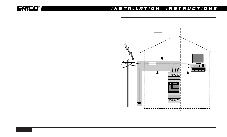
14. TYPICAL DOMESTIC INSTALLATION (from 80A fused supply)
A
TDS140-2S-277
N
T2T1X
L
L
I
I
G
H
T
S
RCD
G
ELCB
H
T
S
G
G
G
P
P
O
O
G
P
P
O
O
RCD Protected
Neutral Neutral Earth
MEN Link
PAGE 29
Page 30

DSD INSTALLATION INSTRUCTIONS
17. EXTENDED WARRANTY
This product has a limited warranty to be free
from defects in materials and workmanship for a
period of five (5) years from the date of dispatch
from the Manufacturer. The Purchaser
acknowledges that lightning is a natural event
with statistical variation in behaviour and energy
levels which may exceed product ratings, and 100 %
protection is not offered and cannot be provided
for. Therefore the Manufacturer’s liability is
limited to the repair or replacement of the product
(at the Manufacturer’s sole option) which in its
judgement has not been abused, misused,
interfered with by any person not authorised by
the Manufacturer, or exposed to energy or
transient levels exceeding the Manufacturer’s
specifications for the product. The product must
be installed and earthed (where applicable) in
strict accordance with the Manufacturer’s
specifications and all relevant national Electricity
and Safety Standards. The Manufacturer and the
PAGE 30
Purchaser mutually acknowledge that the
product, by its nature, may be subject to
degradation as a consequence of the number and
severity of surges and transients that it
experiences in normal use, and that this warranty
excludes such gradual or sudden degradation.
This warranty does not indemnify the Purchaser
of the product for any consequential claim for
damages or loss of operations or service or profits.
Customers should contact their nearest
manufacturer’s agent to obtain a Product Repair
Authorisation Number prior to making any claim
under this warranty. This is only a summary of
the warranty given by the Manufacturer. The full
text of the warranty is set out in the
Manufacturer’s Conditions of Quotation and Sale.
The above limited warranty is additional to rights
which arise in respect of the sale of industrial and
technical products and services to knowledgable
buyers under the Australian Trade Practices Act
1974 as amended.
Page 31

18. SIX POINT PLAN
TDS-DINLINE SURGE SUPPRESSORs form
an important part of the much larger ERICO
lightning, surge and transient protection
philosophy (ERICO Lightning Technologies
“Six Point Plan”). The level of protection and
the degree of attention dedicated to each of
the six points will require careful
consideration for each site. The degree of
protection required is determined by the
individual site location/exposure with the aid
of risk management principals.
For further advice on your protection needs
please contact your local representative.
Capture the
lightning strike
Conduct the strike
to ground safely
Dissipate the energy
through a low
impedance earth
system
Eliminate earth
loops and
differentials
Protect equipment
from surges on
power lines
Protect equipment
from transients on
telecommunication
and signal lines
PAGE 31
Page 32

TDS-DINLINE CONNECTION OPTIONS
Ph-E ProtectionPh-N Protection N-E Protection Ph-Ph Protection
Ph
NPh
E
Ph N
E
NPh
Ph
PhyPh
x
x
Terminals Ph-N Ph-E N-E Ph
www.erico.com
T1 T2 XT1 T2 X
PROTECTION MODE
T1 Ph E E Ph
T2 NPhNPh
X PhNPhPh
T1 T2 X T1 T2 X
x - Phy
x
y
x
 Loading...