

Page 1
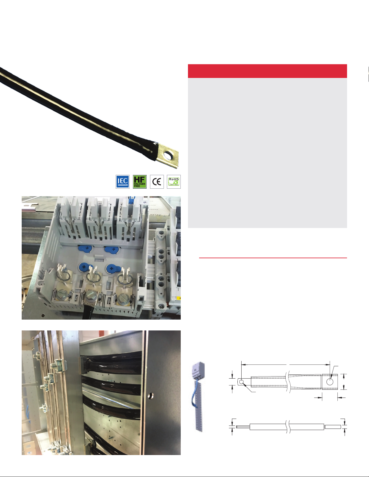
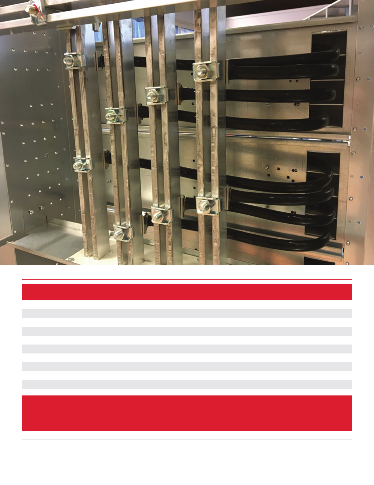
IBSHY Insulated Braided Conductor
2
for Compact Circuit Breakers
FEATURES
• Suitable for all main 125/160 A electrical devices and
specifically molded case circuit breakers
• Resistant to vibration, improving reliability
andperformance
• Improves assembly flexibility and aesthetics
• Quick and easy installation
• No additional cutting, stripping, crimping and
punchingneeded
• Small wire diameter provides maximum flexibility
• Halogen-free solution for applications requiring a low
smokesolution
• Conforms to NF EN 45545 obtaining an HL2
classificationfor chapters R22 and R23
• High working temperature
• RoHS compliant
IBSHY INSULATED BAIDED CONDUCTOR
SPECIFICATIONS
• Typical Application Current Rating: 160 A
• Finish: Tinned
• Material: Copper; Glass Fibre Reinforced Silicon
• Flammability Rating: UL 1441 VW-1
• Max Working Voltage. IEC (Ui): 1 000 VAC; 1 500 VDC
• Operating Temperature: from -60 °C to 250 °C
• Wire Diameter: 0.15 mm
• IEC 60439-1; IEC 61439-1 compliant
A
HS1
CD
L
HS
B
B
Page 2
IBSHY INSULATED BAIDED CONDUCTOR TECHNICAL CHARACTERISTICS
ΔT
40° C
(A)
Cross
Section
ΔT
45° C
(A)
Part No. Article No.
IBSHY32-230 558584 32 mm² 230 mm 11 m m 25 mm 3 mm 5 mm 6.5 mm 10.5 mm
IBSHY32-330 558586 32 mm² 330 mm 11 m m 25 mm 3 mm 5 mm 6.5 mm 10.5 mm
IBSHY32-365 558587 32 mm² 365 mm 11 mm 25 mm 3 mm 5 mm 6.5 mm 10.5 mm
IBSHY32-430 558588 32 mm² 430 mm 11 m m 25 mm 3 mm 5 mm 6.5 mm 10.5 mm
IBSHY32-500 558589 32 mm² 500 mm 11 m m 25 mm 3 mm 5 mm 6.5 mm 10.5 mm
IBSHY32-565 558591 32 mm² 565 mm 11 m m 25 mm 3 mm 5 mm 6.5 mm 10.5 mm
IBSHY32-630 558592 32 mm² 630 mm 11 m m 25 mm 3 mm 5 mm 6.5 mm 10.5 mm
IBSHY32-700 558593 32 mm² 700 mm 11 mm 25 mm 3 mm 5 mm 6.5 mm 10.5 mm
IB SHY32 -765 558594 32 mm² 765 mm 11 mm 25 mm 3 mm 5 mm 6.5 mm 10.5 mm
IBSHY32-830 558595 32 mm² 830 mm 11 m m 25 mm 3 mm 5 mm 6.5 mm 10.5 mm
Cross
Section
(
mm²/
)
kcmil
32/6 3.15 142 153 164 174 184 193 201 209 217 225 235 263 290 1.6 2
ΔT = Temperature of conductors – Internal temperature of panel.
This table indicates the temperature rise produced by chosen current in the given section. This calculation does not take into account the heat dissipation
from the switch gear.
ΔT
30° C
(A)
ΔT
35° C
(A)
Length
L A B C D
Maximum Ampacity Ratings
ΔT
50° C
(A)
ΔT
55° C
(A)
ΔT
60° C
(A)
ΔT
65° C
(A)
ΔT
70° C
(A)
ΔT
75° C
(A)
ΔT
80° C
(A)
ΔT
100°
C
(A)
Hole Size 1
HS1
ΔT
120°
C
(A)
2 Bar
Current
Coefficient
Hole Size 2
HS2
3 Bar
Current
Coefficient
 Loading...