

Page 1

The ERICO CADWELD Process
nVent ERICO Cadweld
Installation and
Inspection Guide
Page 2

WARNING
1. nVent ERICO pr oducts shall be ins talled and used o nly as indicated in nVent E RICO product
instruc tion sheets and tr aining materials . Instruction s heets are availabl e at nVent.com/ERI CO and
from your nVent E RICO customer s ervice repre sentative.
2. nVent ERICO pr oducts must neve r be used for a purpos e other than the pur pose for which they we re
designe d or in a manner that exc eeds specifi ed load ratings.
3. All instru ctions must be co mpletely followe d to ensure proper an d safe installation an d performanc e.
4. Improper i nstallation, mi suse, misapplic ation or other fail ure to completely fol low nVent ERICO’s
instruc tions and warning s may cause produc t malfunction, p roperty dam age, serious bo dily injury
and death.
GENERAL AND SAFETY INSTRUCTIONS:
A. Only nVent ERICO ma nufactured equi pment and materia ls should be used to ma ke nVent ERICO
Cadweld connections.
B. Do not connect i tems except as detai led in instructi on sheets. Failu re to comply with the se
instruc tions may result in i mproper and unsafe c onnections , damage to items bei ng connected,
bodily in jury and
property damage.
C. Do not use worn or bro ken equipment whi ch could cause le akage.
D. D o not alter equipm ent or material wit hout nVent ERICO aut horization.
E. When using C adweld do not use weld ing material pack age if damaged or no t fully intact. Wh en using
Cadweld Pl us, do not tamper wi th or disassembl e the welding mater ial unit.
F. Make connec tions in conform ance with Cadweld i nstructions a nd all governing co des.
1. Personn el should be prop erly trained in th e use of this product a nd must wear safety gl asses
and gloves.
2. Avoid conta ct with hot material s.
3. Advise ne arby personnel o f welding operati ons in the area.
4. Remove or pr otect fire hazard s in the immediate are a.
5. Provide ad equate ventilatio n to the work area.
6. Do not smoke w hen handling sta rting material .
7. Avoid direc t eye contact with “ flash” of light fro m ignition of star ting material.
G. Weld ing material is an exoth ermic mixture a nd reacts to produc e hot molten materia l with
temperat ures in excess of 1400 °C (2500°F) a nd a localized rele ase of smoke. These m aterials are not
explosiv e. Ignition temp eratures are in exces s of 900°C (1650°F ) for welding mater ial.
H. Adhe ring to the Cadweld we lding procedu res will minimize risk o f burns and fire cau sed by hot molten
material sp illage. In case of fi re, use of water or CO
quantiti es of water will aid in con trolling a fire sho uld the exothermi c materials becom e involved.
Water shoul d be applied from a di stance.
1. Make sure the re is proper mold f it and assembly of e quipment.
2. Avoid moistur e and contaminan ts in mold and materia ls being welded. C ontact betwe en hot molten
metal and m oisture or contam inants may result in s pewing of hot materi al.
3. Base materi al thickness mus t be sufficien t for the size and type o f connection be ing made to prevent
melt-th rough and leakag e of hot molten metal.
I. Applicat ions or conditi ons may exist which re quire special co nsiderations . The following are
examples , but are not intende d to be a complete list ing of applicatio ns/conditions.
CONNECTIONS TO PIPE/VESSELS
For use wit h cast iron pipe or he avy casting mee ting ASTM A47- 84, A48 -83, A126-84 , A278-85 , or
A377- 89. DO NOT USE ON CA ST IRON SOIL PI PE (ASTM A74-9 3). Evaluate possibl e effects of Cadwel d
connec tions to structur al members and th in-wall materi als; vessels/pipin g systems that are pre ssurized,
closed or containing (or having contained) flammable/explosive/hazardous materials. Evaluation
should be m ade prior to use, bas ed on condition s of use and applicab le codes, and sho uld incorpora te
as a minimum , effects of melt- through of hot mater ial; structural /metallurgical e ffects of Cadweld
connec tions, pressure ( temperature) build -up and fire/ch emical decom position hazard s.
CONNECTIONS TO REBAR
Applic ation of the Cadweld c onnection may hav e an effect on the reb ar’s structura l integrity. The re bar’s
chemist ry and the locat ion of the weld should b e considered be fore making any welds to t he rebar.
For lappe d rebar splices, i t is recommend ed that the connec tions be made near t he bar end at an area
of minimum s tress. If Cadweld Re bar Splices are us ed, the groundi ng connection c an be made to the
splice sl eeve with minimal ef fect on the struc tural character istics of the splic e.
SAFET Y INSTRUC TIONS:
All gover ning codes and reg ulations and thos e required by the job si te must be observ ed. Always
use appro priate safety equip ment such as eye prote ction, hard hat , and gloves as approp riate to the
application.
WARRANTY
Cadweld pr oducts are warran ted to be free from defe cts in material and wo rkmanship at the ti me of
shipmen t. NO OTHER WARR ANTY, WHE THER EXPRE SS OR IMPLIE D (INCLUDING A NY WARRANT Y
OF MERC HANTABILIT Y OR FITNES S FOR A PARTICUL AR PURPOS E), SHALL E XIST IN CON NECTION
WITH TH E SALE OR USE O F ANY nVent ERICO P RODUCTS. Cla ims for errors, sh ortages, defe cts or
nonconfo rmities ascer tainable upon i nspection mus t be made in writing wi thin 5 days after Bu yer’s
receipt of p roducts. All oth er claims must be ma de in writing to nVent ERI CO within 6 months f rom the
date of shipm ent or transpor t. Products cla imed to be nonconfo rming or defecti ve must, upon nVent
ERICO ’s prior written ap proval in accorda nce with its stand ard terms and proce dures governing r eturns,
promptly b e returned to nVent ERI CO for inspectio n. Claims not made a s provided above and w ithin the
applica ble time period wi ll be barred. nVent ERI CO shall in no event b e responsible if th e products have
not been s tored or used in acco rdance with its sp ecification s and recommend ed procedures . nVent
ERICO wil l, at its option, ei ther repair or rep lace nonconfor ming or defective p roducts for which i t is
responsi ble or return the pu rchase price to the B uyer. THE FOREGO ING STATES BUYER’ S EXCLUSIV E
REMEDY FO R ANY BREAC H OF NVENT ERI CO WARRANT Y AND FOR AN Y CLAIM, WH ETHER
SOUND ING IN CONTR ACT, TORT OR NEGLIGE NCE, FOR LOS S OR INJURY CAU SED BY THE SAL E OR
USE OF A NY PRODUCT.
LIMITATION OF LIABILIT Y
nVent ERICO e xcludes all liabili ty except such lia bility that is dire ctly attribu table to the willful or g ross
neglige nce of nVent ERICO’s em ployees. Shou ld nVent ERICO be hel d liable its liabili ty shall in no
event exce ed the total purchas e price under the c ontract. NVE NT ERICO SHA LL IN NO EVEN T BE
RESPO NSIBLE FOR A NY LOSS OF BUS INESS OR PRO FITS, DOWN TIME OR DELAY, LA BOR, REPAIR OR
MATERIA L COSTS OR AN Y SIMILAR OR D ISSIMIL AR CONSEQU ENTIAL LOS S OR DAMAGE INC URRED
BY BUYE R.
will aid in co ntrol of burning co ntainers. Lar ge
2
Page 3

The nVent ERICO Cadweld Process
The nVent ERICO Cadweld process is a method of making
electrical connections of copper-to-copper or copper-to-steel in
which no outside source of heat or power is required.
In this process, conductors are prepared, placed in a purposedesigned graphite mold, and exothermically welded to produce a
permanent electrical connection.
The steps outlined below are a general demonstration of a typical
welded connection.These basic steps are used for all Cadweld
electrical connections. Be sure to read and follow the instructions
included with every mold before making a connection.
The Cadweld exothermic process is a system. Materials from
other manufacturers should not be mixed or matched with
Cadweld molds or welding material.
The Cadweld Plus Process ........................................... 11
The Cadweld Exolon Process ......................................19
The Cadweld One Shot Process ................................. 28
The Cadweld Plus One Shot Process ........................ 33
Cadweld Quality Standards ......................................... 38
nVent.com/ERICO | 1
Page 4

The Cadweld Process
Fig. 1
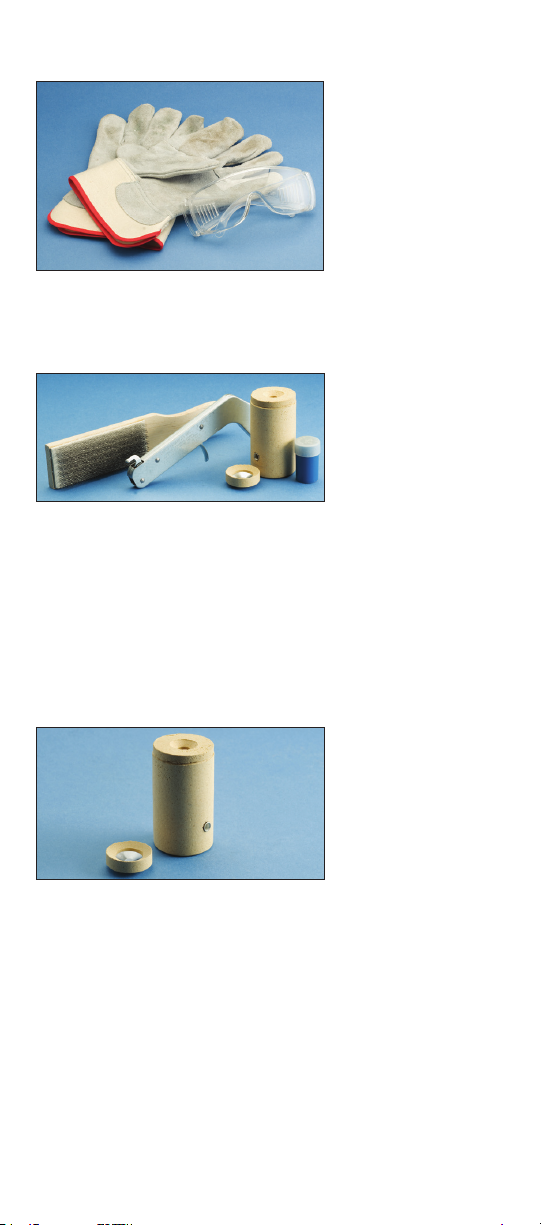
Always wear protective safety glasses and gloves
while working with Cadweld
exothermic welding products.
Fig. 2
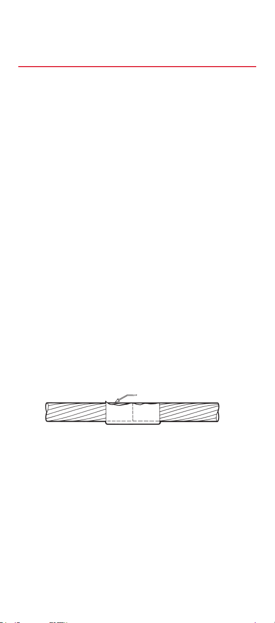
Gather the proper materials and equipment for the type of
connection you are making. The typical Cadweld system requires
a graphite mold, handle clamp, welding material, natural bristle
brush for mold cleaning, wire brush for cleaning/preparing
conductors, flint igniter, and propane torch.
NOTE: Additional materials may be required for your specific
application. Refer to your mold instructions. Advise nearby
personnel of welding operations in the area prior to ignition.
Fig. 3
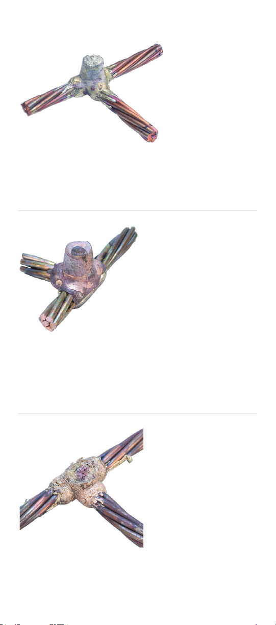
Check to ensure the graphite mold is not worn or broken, which
could cause leakage of molten weld metal during the reaction.
2 | nVent.com/ERICO
Page 5

The Cadweld Process
Fig. 4
Inspect the mold ID tag to ensure that it corresponds to the
application, indicated by the:
1. mold part number
2. conductor size
3. welding material required
4. other materials required
The mold must be correct for the conductor size and application.
DO NOT MODIFY MOLDS.
Fig. 5
Remove the small wire bracket which is used to temporarily hold
the mold together before using. Set the bracket aside.
Fig. 6
Slide the handle clamp into the pre-drilled holes with the proper
orientation for the thumbscrews.
nVent.com/ERICO | 3
Page 6

The Cadweld Process
Fig. 7
Tighten the clamp thumbscrews onto the mold.
Fig. 8
Close the grips to tightly lock the mold. Check for an appropriate
seal on the mold.
Fig. 9
If the mold does not seal properly, make adjustments to tighten/
loosen the handle clamp.
4 | nVent.com/ERICO
Page 7

The Cadweld Process
Fig. 10
Graphite absorbs moisture. Ignite the propane torch and dry out
the inside of the mold thoroughly on both sides, heating the mold
to approximately 250 degrees Fahrenheit (120 degrees Celsius).
Fi g . 11
The conductors should be clean and dry before the connection
is made. Use a propane torch to dry wire conductors and remove
remaining cleaning residue, solvent, or water before making the
Cadweld connection.
Fig. 12
Next, use a wire brush to further prepare the surface of the
conductors (nVent ERICO T-313 or T-314 brush). Scrape the outer
surface to remove dirt and oxidation. You will notice a slight color
change.
nVent.com/ERICO | 5
Page 8

The Cadweld Process
Fig. 13
Insert the conductors and position them for the connection.
Fig. 14
Close the clamp tightly once the conductors are properly
positioned.
Fig. 15
Steel disk found inside the packaging box of welding material.
6 | nVent.com/ERICO
Page 9

The Cadweld Process
Fig. 16
Insert the steel disk (concave side up) into the mold. Hold the
steel disk on the side of the mold and let it slide into place.
Fig. 17
Ensure that the steel disk is properly seated.
Fig. 18
Next, take a tube of properly sized welding material
(as identified on the mold ID tag) out of the box.
nVent.com/ERICO | 7
Page 10

The Cadweld Process
Fig. 19
Remove the lid over the mold crucible.
Fig. 20
Quickly pour the loose welding material powder into the mold.
Fig. 21
The bottom of the tube contains compressed material
(starting material). Tap the bottom of the tube a couple of times
to loosen this material.
8 | nVent.com/ERICO
Page 11

The Cadweld Process
Fig. 22
Pour 1/4 to 1/3 of the starting material over the welding material
in the mold crucible.
Fig. 23
Close the lid and pour the remaining 3/4 to 2/3 of the starting
material into the slot on the mold cover.
NOTE: Welding material is an exothermic mixture and reacts
to produce hot molten material with temperatures in excess
of 2500 degrees Fahrenheit (1400 degrees Celsius) and a
localized release of smoke. Avoid looking directly at the “flash”
of light from ignition of starting material. Avoid inhalation of
smoke/fumes.
Fig. 24
Aiming the flint igniter from the side, ignite the starting material
on the mold cover. Withdraw the igniter quickly to prevent fouling.
Allow approximately 30 seconds for completion of the reaction
and solidification of the molten material.
nVent.com/ERICO | 9
Page 12

The Cadweld Process
Fig. 25
Open the mold and remove the connection. Use care to prevent
chipping the mold. Avoid contact with hot materials. See the
“Cadweld Quality Standards” section to see whether a quality
connection has been made.
Fig. 26
Completed Cadweld connection.
Fig. 27
Cadweld graphite molds will last approximately 50 connections.
Use a soft cotton cloth or a soft bristle brush (nVent ERICO part
#T394) to clean inside the mold cavity and cover.
Fig. 28
Ready to make another Cadweld connection.
10 | nVent.com/ERICO
Page 13

The Cadweld Plus Process
Fig. 1
Always wear protective safety glasses and gloves
while working with Cadweld Plus exothermic products.
Fig. 2
Prepare the proper materials and equipment for the type of
connection you are making. The Cadweld Plus system requires a
graphite mold, mold clamp, Cadweld Plus welding material cup,
natural bristle brush for mold cleaning, wire brush for cleaning/
preparing conductors, control unit, and propane torch.
NOTE: Additional materials may be required for your specific
application. Refer to your mold instructions. Advise nearby
personnel ofwelding operations in the area prior to ignition.
Fig. 3
Check to ensure the graphite mold is not worn or broken, which
could cause leakage of molten weld metal during the reaction.
nVent.com/ERICO | 11
Page 14

The Cadweld Plus Process
Fig. 4
Inspect the mold ID tag to ensure that it corresponds to the
application, indicated by the:
1. mold part number
2. conductor size
3. welding material required
4. other materials required
The mold must be correct for the conductor size and application.
DO NOT MODIFY MOLDS.
Fig. 5
Remove the small wire bracket which is used to temporarily hold
the mold together before using. Set the bracket aside.
Fig. 6
Slide the handle clamp into the pre-drilled holes with the proper
orientation for the thumbscrews.
12 | nVent.com/ERICO
Page 15

The Cadweld Plus Process
Fig. 7
Tighten the clamp thumbscrews onto the mold.
Fig. 8
Close the grips to tightly lock the mold. Check for an appropriate
seal on the mold.
Fig. 9
If the mold does not seal properly, ake adjustments to tighten/
loosen the handle clamp.
nVent.com/ERICO | 13
Page 16

The Cadweld Plus Process
Fig. 10
Graphite absorbs moisture. Ignite the propane torch and dry out
the inside of the mold thoroughly on both sides, heating the mold
to approximately 250 degrees Fahrenheit (120 degrees Celsius).
Fi g. 11
The conductors should be clean and dry before the connection
is made. Use a propane torch to dry wire conductors and remove
remaining cleaning residue, solvent, or water before making the
Cadweld connection.
Fig. 12
Next, use a wire brush to further prepare the surface of the
conductors (nVent ERICO T-313 or T-314 brush). Scrape the outer
surface to remove dirt and oxidation. You will notice a slight color
change.
14 | nVent.com/ERICO
Page 17

The Cadweld Plus Process
Fig. 13
Insert the conductors and position them for the connection.
Fig. 14
Close the clamp tightly once the conductors are properly
positioned.
Fig. 15
Remove the proper Cadweld Plus welding material cup from the
plastic container. Inspect the cup to ensure it is tightly sealed and
the ignition strip is securely attached to the seal.
nVent.com/ERICO | 15
Page 18

The Cadweld Plus Process
Fig. 16
Place the cup into the top of the mold. Make sure the ignition strip
nests into the recess on the top edge when the cover is closed.
Fig. 17
Battery powered control unit.
Fig. 18
Place the ignition strip into the control unit connector. Remove or
protect fire hazards in close proximity to the connection.
16 | nVent.com/ERICO
Page 19

The Cadweld Plus Process
Fig. 19
Close the graphite mold lid. Advise nearby personnel of welding
operations in the area.
Fig. 20
Using the control unit, press the button and hold, while you
observe the “ready” indicator light. A green light will blink for a few
seconds and then will change to a constant light. At this time, the
unit will send a charge to the ignition strip. The ignition strip will
spark inside the metal cup, initiating the Cadweld Plus exothermic
reaction.
Allow approximately 30 seconds for completion of the reaction
and solidification of the molten material.
Fig. 21
Remove the control unit connector from the ignition strip.
Open the lid and remove the used Cadweld Plus cup
from the mold.
nVent.com/ERICO | 17
Page 20

The Cadweld Plus Process
Fig. 22
Open the mold and remove the connection. Use care to prevent
chipping the mold. Avoid contact with hot materials. See the
“Cadweld Quality Standards” section to see whether a quality
connection has been made.
Fig. 23
Completed Cadweld connection.
Fig. 24
Cadweld graphite molds will last approximately 50 connections.
Use a soft cotton cloth or a soft bristle brush (nVent ERICO part
#T394) to clean inside the mold cavity and cover.
Fig. 25
Ready to make another Cadweld connection.
18 | nVent.com/ERICO
Page 21

The Cadweld Exolon Process
Fig. 1
Always wear protective safety glasses and gloves while working
with Cadweld exothermic products.
Fig. 2
Prepare the proper materials and equipment for the type of
connection you are making. The Cadweld Exolon system requires
a Cadweld Exolon graphite mold, handle clamp, welding material,
wire brush for cleaning/preparing conductors, battery pack, and
propane torch.
NOTE: Additional materials may be required for your specific
application. Refer to your mold instructions. Advise nearby
personnel of welding operations in the area prior to ignition.
Fig. 3
Check to ensure the graphite mold is not worn or broken, which
could cause leakage of molten weld metal during the reaction.
nVent.com/ERICO | 19
Page 22

The Cadweld Exolon Process
Fig. 4
Inspect the mold ID tag to ensure that it corresponds
to the application, indicated by the:
1. mold part number
2. conductor size
3. welding material required
4. other materials required
The mold must be correct for the conductor size and application.
DO NOT MODIFY MOLDS.
Fig. 5
Remove the small wire bracket which is used to temporarily hold
the mold together before using. Set the bracket aside.
Fig. 6
Slide the handle clamp into the pre-drilled holes with the proper
orientation for the thumbscrews.
20 | nVent.com/ERICO
Page 23

The Cadweld Exolon Process
Fig. 7
Tighten the clamp thumbscrews onto the mold.
Fig. 8
Close the grips to tightly lock the mold. Check for an appropriate
seal on the mold.
Fig. 9
If the mold does not seal properly, make adjustments to the
handle clamp.
Fig. 10
Graphite absorbs moisture. Ignite the propane torch and dry out
the inside of the mold thoroughly on both sides, heating the mold
to approximately 250 degrees Fahrenheit (120 degrees Celsius).
nVent.com/ERICO | 21
Page 24

The Exolon Process
Fi g . 11
The conductors should be clean and dry before the connection
is made. Use a propane torch to dry wire conductors and remove
remaining cleaning residue, solvent, or water before making the
Cadweld connection.
Fig. 12
Next, use a wire brush to further prepare the surface of the
conductors and ground rod (nVent ERICO T-313 or T-314 brush).
Scrape the outer surface to remove dirt and oxidation.
You will notice a slight color change.
Fig. 13
Weld metal package (includes welding material, discs, filters and
ignitors for 4 connections).
22 | nVent.com/ERICO
Page 25

The Exolon Process
Fig. 14
Each Exolon package contains 2 filters for a low emission
connection. Insert the white ceramic and black graphite
filters into the mold cover. (Filters must be changed every
4 connections.)
NOTE: If using XL200 welding material or higher, 3 filters
(1 white, 2 black) are included in the weld metal package.
Insert the white filter between the black filters.
Fig. 15
Insert the conductors and position them for the connection.
Fig. 16
Close the clamp tightly once the conductors are properly
positioned.
nVent.com/ERICO | 23
Page 26

The Cadweld Exolon Process
Fig. 17
Steel disk found inside the packaging box of welding material.
Fig. 18
Insert the steel disk (concave side up) into the mold. Hold the
steel disk on the side of the mold and let it slide into place.
Fig. 19
Ensure that the steel disk is properly seated.
Fig. 20
Next, take the tube of welding material included in the
Cadweld Exolon package and remove the lid over
the mold crucible.
24 | nVent.com/ERICO
Page 27

The Cadweld Exolon Process
Fig. 21
Quickly pour the loose welding material powder into the
Cadweld Exolon mold.
NOTE: Welding material is an exothermic mixture and reacts
to produce hot molten material with temperatures in excess
of2500 degrees Fahrenheit (1400 degrees Celsius) and a
localized release of smoke. Avoid direct eye contact with “flash”
of light from ignition of starting material. Avoid inhalation of
smoke/fumes.
Fig. 22
Place the graphite Cadweld Exolon cover onto the mold, with the
larger side facing down.
Fig. 23
Next, take an igniter pin and place it halfway into the small hole
on the side of the mold, with the loop side facing into the hole.
Spread the wire leads.
nVent.com/ERICO | 25
Page 28

The Cadweld Exolon Process
Fig. 24
Cadweld Exolon battery pack.
Fig. 25
Take the alligator clips and clip them onto the wire leads. Remove
or protect fire hazards in close proximity to the connection.
Advise nearby personnel of welding operations in the area.
Fig. 26
Using the Cadweld Exolon battery pack, press the button. At this
time, the unit will send a charge to the igniter pin. The igniter pin
will initiate the Cadweld Exolon exothermic reaction.
Allow approximately 30 seconds for completion of the reaction
and solidification of the molten material.
Fig. 27
Remove the alligator clips from the igniter pin. Remove the
graphite cover of the Cadweld Exolon mold.
26 | nVent.com/ERICO
Page 29

The Cadweld Exolon Process
Fig. 28
Open the mold and remove the connection. Use care to prevent
chipping the mold. Avoid contact with hot materials. See the
“Cadweld Quality Standards” section to see whether a quality
connection has been made.
Fig. 29
Completed Cadweld connection.
Fig. 30
Cadweld Exolon graphite molds will last approximately 50
connections. Use a soft cotton cloth or a soft bristle brush (nVent
ERICO part #T394) to clean inside the mold cavity and cover;
remove any slag left from the exothermic reaction.
Fig. 31
Ready to make another Cadweld connection.
nVent.com/ERICO | 27
Page 30
The Cadweld One Shot Process
Fig. 1
Always wear protective safety glasses and gloves while working
with Cadweld exothermic products.
Fig. 2
Gather the proper materials and equipment for the type of
connection you are making. The Cadweld One Shot system
requires a Cadweld One Shot ceramic mold, welding material, wire
brush for cleaning/preparing conductors, flint igniter, and propane
torch.
NOTE: Additional materials may be required for your specific
application. Refer to your mold instructions. Advise nearby personnel of
welding operations in the area prior to ignition.
Fig. 3
Check to ensure the ceramic mold is not broken, which could
cause leakage of molten weld metal during the reaction.
Inspect the Cadweld One Shot box label to ensure that it
corresponds to the application, indicated by the:
1. Cadweld One Shot part number
2. conductor size
3. welding material required
4. other materials required
The mold must be correct for the conductor size and application.
DO NOT MODIFY MOLDS.
28 | nVent.com/ERICO
Page 31

The Cadweld One Shot Process
Fig. 4
The conductors should be clean and dry before the connection
is made. Use a propane torch to dry wire conductors and remove
remaining cleaning residue, solvent, or water before making the
Cadweld One Shot connection.
Fig. 5
Next, use a wire brush to further prepare the surface of the
conductors and ground rod (Cadweld T-313 or
T-314 brush).
Scrape the outer surface to remove dirt and oxidation.
You will notice a slight color change.
Fig. 6
Each Cadweld One Shot contains a rubber grommet
at the bottom of the mold.
Gently turn the Cadweld One Shot onto the ground
rod until the ground rod reaches the stopper and cannot go
any fur ther.
nVent.com/ERICO | 29
Page 32

The Cadweld One Shot Process
Fig. 7
Insert the conductors and position them for the connection.
Fig. 8
Place the steel disk into the Cadweld One Shot
with the concave side facing up.
Fig. 9
Ensure that the steel disk is properly seated inside the
Cadweld One Shot.
Fig. 10
Next, take the tube of welding material included in the
Cadweld One Shot package and remove the lid
over the crucible.
30 | nVent.com/ERICO
Page 33

The Cadweld One Shot Process
Fi g. 11
Quickly pour the loose welding material powder into the
Cadweld One Shot mold.
Fig. 12
Place the cover on the top of the Cadweld One Shot.
Fig. 13
The bottom of the tube contains compressed material
(starting material). Tap the bottom of the tube a couple of
times to loosen this material.
Fig. 14
Pour the starting material onto the Cadweld One Shot cover.
NOTE: Welding material is an exothermic mixture and reacts to produce
hot molten material with temperatures in excess of 2500 degrees
Fahrenheit (1400 degrees Celsius) and a localized release of smoke.
Avoid direct eye contact with “flash” of light from ignition of starting
material. Avoid inhalation of smoke/fumes.
nVent.com/ERICO | 31
Page 34

The Cadweld One Shot Process
Fig. 15
Aiming the flint igniter from the side, ignite the starting material
on the mold cover. Withdraw the igniter quickly to prevent fouling.
Allow approximately 30 seconds for completion of the reaction
and solidification of the molten material.
Fig. 16
Break the ceramic Cadweld One Shot mold off of the connection.
Avoid contact with hot materials. See the “Cadweld Quality
Standards” section to see whether a quality connection has been
made.
Fig. 17
You are ready to make another Cadweld One Shot connection.
32 | nVent.com/ERICO
Page 35

The Cadweld Plus One Shot Process
Fig. 1
Always wear protective safety glasses and gloves while working
with Cadweld exothermic products.
Fig. 2
Prepare the proper materials and equipment for the type of
connection you are making. The Cadweld Plus One Shot system
requires a Cadweld One Shot ceramic mold, Cadweld Plus
welding material, wire brush for cleaning/preparing conductors,
control unit, and propane torch.
NOTE: Additional materials may be required for your specific
application. Refer to your mold instructions.
Fig. 3
Check to ensure the ceramic mold is not worn or broken, which
could cause leakage of molten weld metal during the reaction.
Inspect the Cadweld Plus One Shot box label to ensure that it
corresponds to the application, indicated by the:
1. Cadweld Plus One Shot part number
2. conductor size
3. welding material required
4. other materials required
The mold must be correct for the conductor
size and application. DO NOT MODIFY MOLDS.
nVent.com/ERICO | 33
Page 36

The Cadweld Plus One Shot Process
Fig. 4
The conductors should be clean and dry before the connection
is made. Use a propane torch to dry wire conductors and remove
remaining cleaning residue, solvent, or water before making the
Cadweld connection.
Fig. 5
Next, use a wire brush to further prepare the surface of
the conductors and ground rod (nVent ERICO T-313 or
T-314 brush).
Scrape the outer surface to remove dirt and oxidation.
You will notice a slight color change.
Fig. 6
Each Cadweld Plus One Shot contains a copper wire at the
bottom of the mold.
Place the mold onto the ground rod until the ground rod reaches
the wire stopper and cannot go any further.
34 | nVent.com/ERICO
Page 37

The Cadweld Plus One Shot Process
Fig. 7
Insert the conductors and position them for the connection.
Fig. 8
Inspect the cup to ensure it is tightly sealed and the ignition strip
is securely attached to the seal.
Fig. 9
Place the welding material cup into the top of the mold. Make sure
the ignition strip nests into the recess on the top edge.
Fig. 10
Place the ceramic lid onto the mold.
nVent.com/ERICO | 35
Page 38

The Cadweld Plus One Shot Process
Fi g. 11
Battery powered control unit.
Fig. 12
Place the ignition strip into the control unit connector. Remove or
protect fire hazards in close proximity to the connection. Advise
nearby personnel of welding operations in the area.
Fig. 13
Using the control unit, press the button and hold, while you
observe the “ready” indicator light. A green light will blink for a
few seconds and then will change to a constant light. At this
time, the unit will send a charge to the ignition strip. The ignition
strip will spark inside the metal cup, activating the Cadweld Plus
exothermic reaction.
Allow approximately 30 seconds for completion of the reaction
and solidification of the molten material.
36 | nVent.com/ERICO
Page 39

The Cadweld Plus One Shot Process
Fig. 14
Remove and dispose of the used Cadweld Plus weld metal cup.
Fig. 15
Break the ceramic Cadweld One Shot mold off of the connection.
Avoid contact with hot materials. See the “Cadweld Quality
Standards” section to see whether a quality connection has been
made.
Fig. 16
You are ready to make another Cadweld connection.
nVent.com/ERICO | 37
Page 40

Cadweld Quality Standards
All Cadweld materials are produced to high standards under
stringent quality control. All Cadweld connections are designed and
tested using Cadweld molds, welding materials, and accessories.
In the absence of any standards, national or international, we
cannot accurately predict the individual product standards of
our competition, either known or unknown. Therefore, mixing of
one manufacturer’s molds with another manufacturer’s welding
materials can predictably lead to finished welds that do not
meet the standards of either manufacturer. After all, one of the
advantages of exothermic welding as a welding process is the
fact that it is pre-engineered.
Specifications for Cadweld Connections
All grounding system connections shall be made by the Cadweld
process. Connections shall include, but not be limited to, all cable
to cable splices, T’s, X’s, etc.; all cable to ground rods, ground rod
splices, cable to steel and cast iron; and cable lug terminations.
Procedures listed in all Cadweld instructions shall be followed.
Molds shall not be altered in the field.
All materials used (molds, welding material, tools, accessories,
etc.) shall be Cadweld materials, manufactured by nVent ERICO.
Materials of different manufacturers shall not be mixed.
A Cadweld mold is designed to last for an average of 50
connections. This will vary according to the care given the mold
during use.
Inspect the mold regularly. Check the following items to
determine if a mold should be replaced:
38 | nVent.com/ERICO
Page 41

Cadweld Quality Standards
CADWELD MOLD INSPECTION
Chip in mold
parting face
Mold par ting
face smo oth
Tap hole
well dened
Weld cavity
well dened
Good
Replace
Disk seat worn
Mold par ting
face has
erosion lines
Chip in weld
cavity
Cable opening
worn
Cable Opening
• The conductor should fit snugly. A loose fit will cause leakage.
• The opening should not be chipped or worn.
Weld Cavity
• The cavity should be well defined.
• There should be no chips or gouges.
Tap Hole
• The tap hole should be well defined.
Disk Seat
• The seat should not be worn or chipped; the disk must seat
properly.
Mold Parting Face
• The parting face should not be chipped.
• The parting face should always be cleaned properly. Use a clean
shop towel or newspaper and wipe clean. Using a wire brush to
clean the mold will cause erosion and quickly destroy the mold.
nVent.com/ERICO | 39
Page 42
Cadweld Quality Standards
INSPECTION OF CADWELD CONNECTIONS GENERAL
INDICATORS
Proper inspection of a Cadweld connection relies on the judgment
of the field personnel. Look closely at the size, color, surface
finish, and porosity of the connection.
Following the guidelines below will assist in making meaningful
inspections. Photographs of good, acceptable, and reject
connections appear on pages 14 – 17.
SIZE
1. No portion of the conductor within the confines of the weld
should be exposed.
2. Maximum depression under the riser on horizontal
connections (after the slag has been removed) should be no
lower than the top of the conductor.
A low fill indicates:
(a) Not enough welding material was used.
(b) Excessive leakage of molten metal.
(c) Improper positioning of the conductor inside the mold.
(d) Movement of conductor.
3. Excessively high fill (tall riser) indicates:
(a) Too large welding material size was used (connection is
still acceptable).
(b) Apparent volume increase due to contaminants in
conductor or mold (see “Porosity” on page 12).
40 | nVent.com/ERICO
Strands showing
(below weld level)
Unacceptable
Page 43

Cadweld Quality Standards
Higher than normal
Normal
Minimum acceptable
Typ e VS
Higher than normal
Normal
Minimum acceptable
Typ e GT
Typ e SS
Higher than normal
Normal
Minimum acceptable
nVent.com/ERICO | 41
Page 44

Cadweld Quality Standards
INSPECTION OF
CADWELD CONNECTIONS
GENERAL INDICATORS (CONTINUED)
Color
The color of a Cadweld connection is best seen after a light wire
brushing of the connection. It should normally be gold to bronze
in color. Occasionally, it may be silvery at the top. This silver color
indicates “tin sweat” of the surface, a normal condition.
A Cadweld connection to cast iron or galvanized surfaces is often
silvery due to alloying with the metals.
Surface Finish
The surface of a Cadweld connection should be reasonably
smooth and free of major slag deposits. If slag deposits cover
more than 20% of the connection surface, or if any cable strands
are exposed after slag has been removed, the connection must
be rejected.
Porosity
The connection should be essentially free from porosity.
Excessive porosity is normally the result of contaminants
(water, oil, dirt, etc.) in the conductor and/or mold. A few small
pinholes may be present on the surface of the riser. The depth of
a pinhole must never extend beyond the center of the conductor.
To check the depth, probe the pinhole with a 1/32-in.-diameter
wire (paper clip). Reject the connection if the depth of the pinhole
extends beyond the center of the conductor.
42 | nVent.com/ERICO
Page 45

Cadweld Quality Standards
INSPECTION OF
CADWELD CONNECTIONS
VISUAL INSPECTION
Photographic Guides
Like all electrical connections, a visual inspection is no guarantee
of performance. Crimped or bolted connections cannot be
inspected visually, but Cadweld connections can be visually
inspected and provide an indication of the quality of the weld.
Visual inspection is recommended as a practical minimum.
Use the photographs on the following pages as a guide to visual
inspection. Cadweld connections are normally rated as good,
acceptable or reject.
A good connection is a normal weld with only minor surface
imperfections.
An acceptable connection is a less than normal weld, but a good
performing weld. Imperfections indicate that 1) a new mold is
required, 2) a change in procedure is necessary, or 3) the proper
mold conductor and/or welding material should be used.
A reject connection shows inadequate fill or an extra high
riser due to 1) use of incorrect procedure, 2) use of incorrect
equipment and/or equipment worn beyond its useful life, or 3)
use of incorrect material.
nVent.com/ERICO | 43
Page 46

Cadweld Quality Standards
INSPECTION OF
CADWELD CONNECTIONS
PHOTOGRAPHIC GUIDES
Good.
A solid weld with only minor surface imperfections.
Acceptable.
Fill is lower than normal, but still sufficient.
Reject.
A worn or incorrect mold was used, allowing leakage around
conductor. The fill in this connection is insufficient to allow it as
acceptable. Replacement of mold is required prior to making next
connection.
44 | nVent.com/ERICO
Page 47
Cadweld Quality Standards
Acceptable.
The presence of water/moisture in conductor strands or mold
indicates that one or both were not properly dried. Although the
riser is porous, the weld is solid. The degree of porosity is not
sufficient to reject this connection.
Reject.
Extreme amounts of slag on surface are caused by welding
material leaking past disk or complete lack of disk. Inspect the
condition of mold disk seat and check disk positioning prior to
making the next connection.
Reject.
Excessive water in cable strands and/or mold.
nVent.com/ERICO | 45
Page 48

Cadweld Quality Standards
INSPECTION OF
CADWELD CONNECTIONS
PHOTOGRAPHIC GUIDES (CONTINUED)
Reject.
Light carbon traces on cable and connection are evidence of oil
on cable strands. Oily cables must be cleaned with safety solvent.
Reject.
Heavy carbon coating on cable and connection is evidence of large
amounts of oil or grease on cable. Cable must be cleaned with
safety solvent.
46 | nVent.com/ERICO
Page 49

Cadweld Quality Standards
Reject.
Fill too low. Weld cavity was not filled over cable strands. “Fins”
indicate that the mold was not closed tightly due to incorrect
mold, incorrectly adjusted handle clamp, or presence of foreign
material in mold parting line. Before making the next connection,
check the mold for each of the above.
Reject.
Fill too low. Weld cavity was not filled over cable strands.
Absence of leakage indicates that welding material size was
incorrect (too small) or thru conductor moved.
nVent.com/ERICO | 47
Page 50

Cadweld Quality Standards
FIELD SITUATION GUIDE
Most field difficulties can be overcome by checking the
following problems.
PROBLEM A
The mold doesn’t close tightly.
Check for:
1. Adjustment of handle clamps.
2. Cables out of round or bent.
3. Dirt or slag in mold parting line.
4. Correct cable size.
NOTE: Use “C” clamp if necessary.
PROBLEM B
The connection is covered with excessive slag.
Check for:
1. Welding material leaking past the disk, caused by:
(a) Chipped graphite at tap hole.
(b) Disk moved when welding material was dumped.
(c) Disk not properly seated.
(d) Disk was not installed.
NOTE: A small amount of slag on the surface is not abnormal.
PROBLEM C
Molten metal “spits” out of the crucible when making a
connection.
Remedy:
1. See Problem D.
48 | nVent.com/ERICO
Page 51

Cadweld Quality Standards
PROBLEM D
The connection is porous
Check for:
1. Presence of moisture either in conductor or mold.
Remedy:
(a) Dry the conductor by wiping and heating.
(b) Heat mold with torch (to above 212°F) or by igniting
welding material in mold without any conductors, taking
care to prevent burns from the hot material running out
of the mold.
NOTE: Do not use the second method of heating if the mold
has wear plates.
Check for:
2. Other contaminants (oil, insulation, etc.) present in
conductors.
Remedy:
(a) Use a safety solvent to wash the conductor, then dry it.
(b) If insulation is present between strands, remove it.
Check for:
3. Mold packing material in weld cavity of mold.
Remedy:
(a) Always apply mold packing material to conductor after
mold is closed.
PROBLEM E
The conductors do not weld
Check for:
1. Conductors were not properly cleaned and dried.
Remedy:
(a) Remove oxides with a wire brush. If heavily oxidized, have
fresh-cut conductor end and use Cadweld Heavy Duty
molds.
(b) Dry conductors with a torch.
Check for:
2. Conductors not properly positioned in the mold.
Remedy:
(a) Check for proper gap or butting as required (see the mold
tag and read the instructions packaged with mold).
nVent.com/ERICO | 49
Page 52

Cadweld Quality Standards
Field Situation Guide (continued)
(b) Check to be sure gap is centered under tap hole.
NOTE: In some cases, the run (thru) conductor must be cut
and gapped. Follow instructions for same or use Cadweld
Heavy Duty molds.
PROBLEM F
The welding material leaks around the conductor.
Remedy:
1. Use packing material around the conductor after the mold is
closed.
2. Use molds with wear plates (which also act as chill plates).
3. Check for the proper mold. Mold must be sized for the cable
being welded.
4. If the mold is excessively worn, replace with a new mold.
PROBLEM G
The connection has “fins”— metal is lost.
Check for:
1. Mold not completely closed.
2. Mold worn beyond useful life and needs replacement.
PROBLEM H
The cables pull out of the mold during welding.
Remedy:
1. Use a clamp (Cadweld B-265) or other means to prevent
movement of conductors when welding.
PROBLEM I
Insufficient fill material to cover conductors
Check for:
1. Use of proper welding material size (see mold tag).
2. Too large a gap between conductors (see positioning
instructions).
3. Mold leakage.
50 | nVent.com/ERICO
Page 53

Cadweld Quality Standards
Remedy:
(a) See Problem F.
(b) See Problem G.
(c) See Problem H.
4. Conductor movement.
PROBLEM J
The riser is too high.
Check for:
1. Use of proper welding material size (see mold tag).
2. Moisture in mold or conductor.
Remedy:
(a) See Problem D.
PROBLEM K
The mold wears out quickly.
(Molds should produce an average of 50 connections.)
Remedy:
1. Use Cadweld B-265 cable clamp for hard-drawn copper or
DSA Copperweld
2. Clean the mold with a soft brush, clean cloth, or newspaper.
DO NOT USE A WIRE BRUSH.
3. Use care in removing the mold from a finished connection to
prevent chipping of mold.
®
.
PROBLEM L
When welding to steel, the weld does not “stick” to the steel.
Remedy:
1. Clean the steel with a rasp or grinder to bright metal.
When grinding, use an nVent ERICO approved grinding
wheel only. All mill scale, paint, and/or other coating must
be removed. Wire brushing will NOT suffice. Grease must be
removed with safety solvent before cleaning.
2. Clean galvanized surfaces with a wire brush or emery cloth.
However, extra heavy galvanized steel must be cleaned with
a rasp.
3. If the steel is moist, heat with a torch (from the back side
if possible). Any carbon deposit from the flame must be
removed.
4. If conductors are not in proper position, check the
instruction sheet.
nVent.com/ERICO | 51
Page 54

Cadweld Quality Standards
Field Situation Guide (continued)
PROBLEM M
When welding to ductile iron or cast iron, the weld does not
“stick” to the surface.
Remedy:
1. Remove all coatings before cleaning.
2. Clean the surface with a rasp or grinder to bright metal. When
grinding, use an nVent ERICO-approved wheel only.
3. Clean the surface with a safety solvent after grinding or
rasping.
4. Use Cadweld XF-19 alloy welding material (orange cap).
52 | nVent.com/ERICO
Page 55

Page 56

Our powerful portfolio of brands:
CADDY ER ICO HO FFMA N RAYCHEM SCHROF F TRAC ER
nVent.com/ERICO
©2018 nVent. All nVent marks and logos are owned or licensed by nVent Ser vices
GmbH or its affiliates. All other trad emarks are the prop erty of their respective owners.
nVent reser ves the right to change specifications without notice.
ERICO-CAT-E1294W-E297LT17WW-EN-1805
 Loading...