

Page 1
INSTRUCTION SHEET
IBTB
INTERSYSTEM BONDING TERMINATION
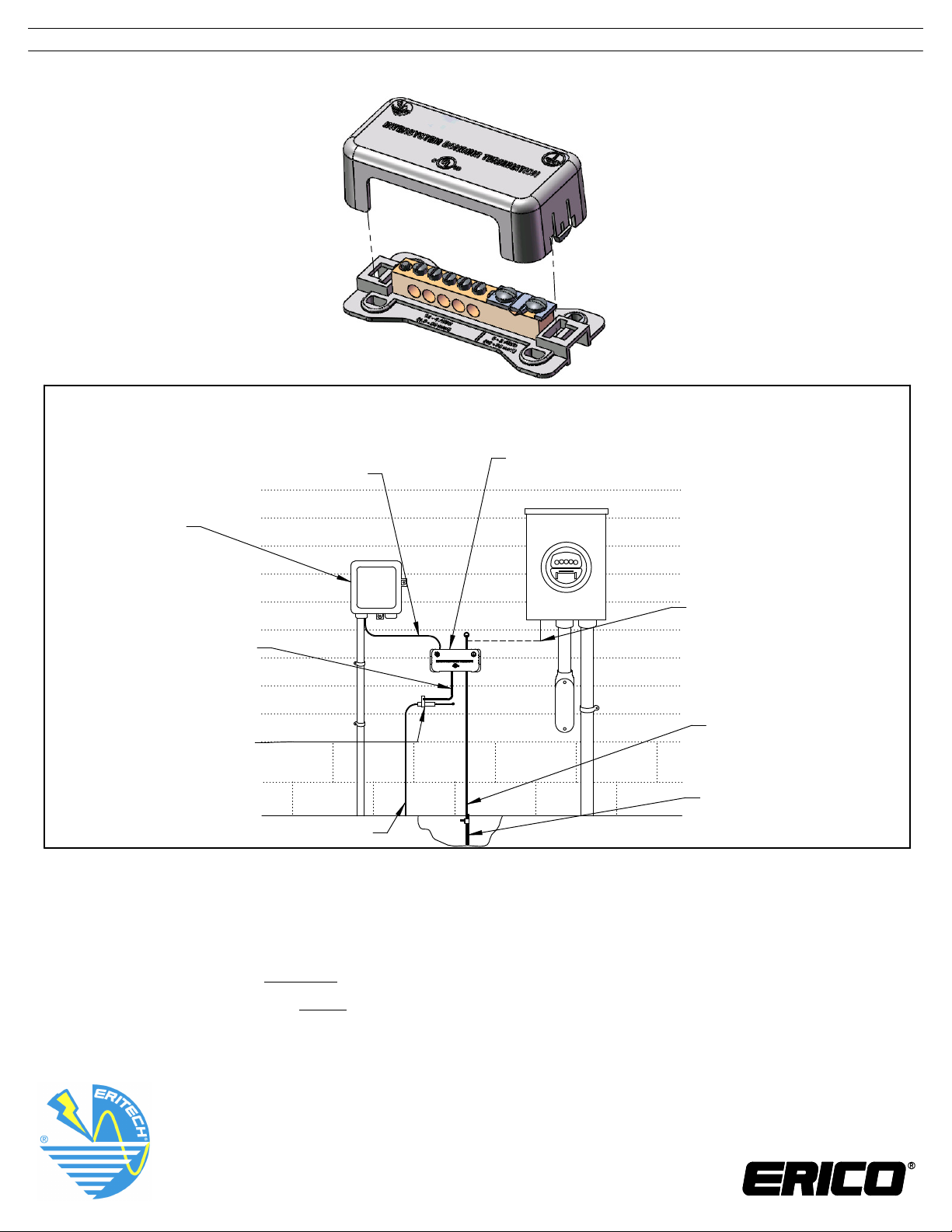
Example of Intersystem Bonding Termination
Installation- Residential Service
IBTBTelephone Grounding
Conductor
Telephone
NID
Alternate Location For
Connection of Grounding
Electrode Connector
(Accessible Meter Enclosure).
Other acceptable bonding
CATV Grounding
methods not shown.
Conductor
CATV Grounding
Block
Grounding
Electrode
Conductor
Ground Rod
Electrode
CATV
Note:
Intersystem Bonding Termination is also used to bond grounding conductors from television and
radio antennas, satellite dish cable, antenna discharge units and lightning protection systems.
Warning:
1. Do not disconnect the electrical service grounding conductors while the system is energized.
2. Follow all local electrical codes as required by Authority Having Jurisdiction.
WARNING:
1. ERICO products shall be installed and used only as indicated in ERICO product instruction sheets and training materials. Instruction sheets
are available at www.erico.com and from your ERICO customer service representative.
2. ERICO products must never be used for a purpose other than the purpose for which they were designed or in a manner that exceeds
specified load ratings.
3. All instructions must be completely followed to ensure proper and safe installation and performance.
4. Improper installation, misuse, misapplication or other failure to completely follow ERICO's instructions and warnings may cause product malfunction,
property damage, serious bodily injury and death.
The customer is responsible for:
a. Conformance to all governing codes.
b. The integrity of structures to which the products are attached, including their capability of safely accepting the loads imposed, as evaluated by a
qualified engineer.
c. Using appropriate industry standard hardware as noted above.
SAFETY INSTRUCTIONS:
All governing codes and regulations and those required by the job site must be observed.
Always use appropriate safety equipment such as eye protection, hard hat, and gloves as appropriate to the application.
UL is a registered trademark of Underwriters Laboratories, Inc.
CADDY, CADWELD, CRITEC, ERICO, ERIFLEX, ERITECH, and LENTON are registered trademarks of ERICO International Corporation.
TECHNICAL SUPPORT:
www.erico.com
CFS380_F
1 OF 2
2009 ERICO International Corporation
©
Page 2
INSTRUCTION SHEET
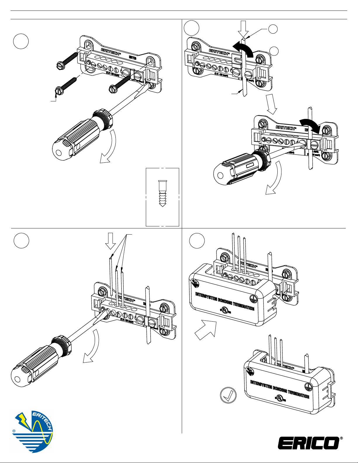
INSTALLATION:
#1
1/8" [3.2mm]
DRILL
FOR PILOT
(4X)
20 in-lb
[2.6 N-m]
(4X)
IF REQ'D
#2
SEE NOTE 2
1
2
35 in-lb
[4 N-m]
(2X)
6 - 2 AWG [16- 35mm2]
1
Grounding Electrode
Conductor
2
6 - 2 AWG [16- 35mm2] to
grounding electrode
conductor, equipment
grounding conductors in
service entrance enclosure
or exposed non flexible
metallic raceway
3
4
NOTE 1: Mounting hardware
and anchors included.
#3
2
35 in-lb
[4 N-m]
1/4" [6.4mm]
DRILL
(4X)
NOTE 2: UL Listed for 6 - 2 AWG Solid
and 6 AWG Stranded
BONDING
1
14 - 4 AWG
CONDUCTORS
#4
[1.5mm2- 25mm2]
SEE NOTE 3
NOTE 3: UL Listed for 14 - 6 AWG Solid
®
and 14 - 4 AWG Stranded
NOTE 4: Torque value for 6 AWG Solid
[16mm2] is 40 in-lb [4.5 n-m]
TECHNICAL SUPPORT:
www.erico.com
CFS380_F
2 OF 2
2009 ERICO International Corporation
©
 Loading...