

Page 1
EPD
UNITLG ( )
SENSITIVE
ELECTRONICS
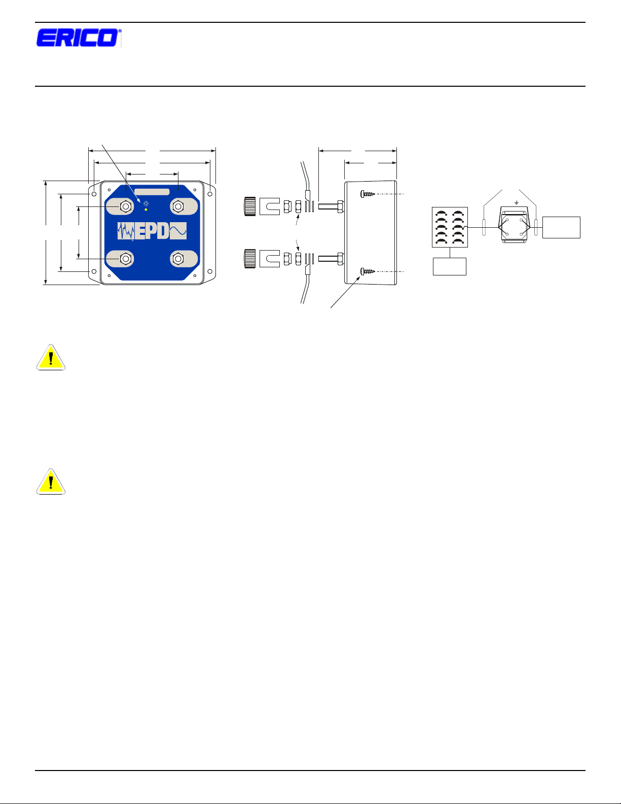
MOUNTING SCREWS
SUPPLIED
STATUS INDICATOR
Secondary Surge Protectors
Series TVSS Filters
EPD120TDAARB (120 Vac 0-30A)
EPD240TDAARB (240 Vac, 0-30A)
Installation Instructions
5 3/4
5 1/4
2 3/8
CAUTION! 30A MAX.
= OK
R
www.erico.com
FIG. 1 FIG. 2
INPUT
TM
OUTPUT
L
AAR HARDWARE
SUPPLIED
L
4 3/4
3 1/2
2 3/8
INPUT
N
ERICO PROTECTION DEVICES
OUTPUT
N
DANGER: Electrical shock or burn hazard.
Installation of Secondary Surge Protector should be
made by qualified personnel. Failure to lockout
electrical power during installation or maintenance can
result in fatal electrocution or severe burns.
1. Disconnect and lockout power to the point where the
Secondary Surge Protector (EPD unit) is to be installed.
Follow all applicable electrical codes & procedures.
CAUTION: Check to make sure line voltage does
not exceed EPD unit voltage requirement. These
EPD units do not have overcurrent protection, and
should be fed from an appropriately sized breaker (<= 30A).
2. Mount the EPD unit as close as possible to the sensitive
electronics being protected. See FIG. 3.
3 1/2
2 3/8
TWIST
FIG. 3
WIRING
NLN
SECONDARY
PROTECTOR
LOAD CENTER OR
BREAKER BOX
PRIMARY
PROTECTOR
8. Engage power to the EPD unit. Status LED should
illuminate indicating correct operation. If not, disconnect
power, check wiring, rectify any deficiencies, and reapply
power. If still experiencing difficulties, please contact
your supplier, or the manufacturer:
ERICO, Inc.
Rail Electrical Products
34600 Solon Rd
Solon OH 44139 USA
Ph. (800) 447-7245
Ph. (440) 542-3939
3. For mounting, use layout of holes as indicated in FIG. 1;
4. Output wires should be kept as SHORT as possible
5. Input and output wires to and from the EPD unit should
6. Use A.A.R. hardware supplied. See FIG. 2 for assembly.
7. The LED on the front panel illuminates to indicate that
2003 ERICO Inc, 34600 Solon Rd, Solon, OH 44139 Page 1 of 1 Document Number: HBCR1671 Revision: 1
drill 9/64 diameter holes in the mounting surface for the
#8 x 1/2-lg. screws provided.
between equipment and the EPD unit, and the input and
output wires should be twisted to minimize noise
coupling.
be separated to minimize noise coupling.
the protection circuitry is operating correctly. If LED has
extinguished, the EPD unit has sustained a surge beyond
its ratings and the unit should be replaced immediately as
no protection may be provided.
 Loading...