

Page 1
EPD
UNIT
BATTERY
CHARGER
SENSITIVE
ELECTRONICS
MOUNTING SCREWS
SUPPLIED
TWIST
WIRING
STATUS INDICATOR
12V
24V
LINK
NO LINK
Secondary Surge Protector
EPD1224ATAAR (12/24Vdc, 30A)
Installation Instructions
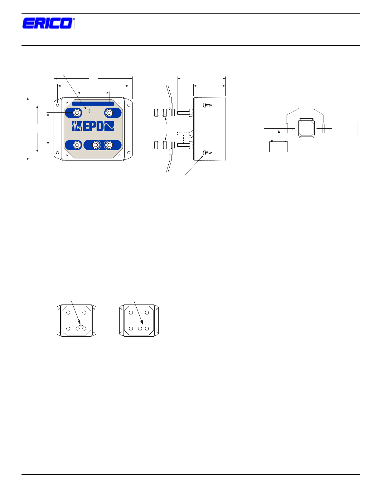
5 3/4
5 1/4
2 3/8
CAUTION !
30A MAX. IN-LINE, OR 60A TAPPED FROM INPUT TERMINALS
= OK
R
12/24 VDC PROTECTOR
LINK
www.erico.com
FIG. 1 FIG. 2
LINK ON - 12V
LINK OFF - 24V
INPUT
POS +
TM
OUTPUT
POS +
AAR HARDWARE
SUPPLIED
4 3/4
3 1/2
2 3/8
INPUT
NEG -
ERICO PROTECTION DEVICES
OUTPUT
NEG -
1. Installation of Secondary Surge Protector (EPD unit)
should be by qualified personnel. Follow all applicable
electrical codes and procedures.
2. Disconnect and lockout power to the point where the
EPD unit is to be installed.
3. For 12V systems ensure the link from LINK terminal to
OUTPUT POS + terminal is installed. Line voltage
should not exceed 18 Vdc or the unit may be damaged.
For 24V systems ensure that the LINK terminal is not
connected to the OUTPUT POS + terminal. Line voltage
should not exceed 36 Vdc or the unit may be damaged.
Fig 4
4. Mount the EPD unit as close as possible to the sensitive
electronics being protected.
5. For mounting, use layout of holes as indicated in FIG. 1;
drill 9/64 diameter holes in the mounting surface for the
#8 x 1/2-lg. screws provided.
3 1/2
2 3/8
BATTERIES
FIG. 3
7. Input and output wires to and from the filter unit should
be separated to minimize noise coupling.
8. EPD1224ATAAR does not have overcurrent protection.
The current in the circuit must not exceed the EPD unit
rating (30A).
9. The LED on the front panel illuminates to indicate that
the protection circuitry is operating correctly. If LED has
extinguished, the EPD unit has sustained a surge beyond
its ratings and the unit should be replaced immediately as
no protection may be provided.
10. Check wiring polarity matches EPD terminal marking.
Reverse polarity may damage the indication circuitry.
Engage power to the EPD unit. Status LED should
illuminate indicating correct operation. If not, disconnect
power, check wiring, EPD voltage selection link, rectify
any deficiencies, and reapply power. If still experiencing
difficulties, please contact your supplier, or the
manufacturer:
ERICO, Inc.
Rail Electrical Products
34600 Solon Rd
Solon OH 44139 USA
Ph. (800) 447-7245
6. Output wires should be kept as SHORT as possible
2003 ERICO Inc, 34600 Solon Rd, Solon, OH 44139 Page 1 of 1 Document Number: HBCR1661 Revision: 2
between equipment and the EPD unit, and the input and
output wires should be twisted to minimize noise
coupling. Use A.A.R. hardware supplied. See FIG. 2 for
assembly.
 Loading...