

Page 1
Automatic Threader
Instruction Manual
ELAT100
Page 2

Table of Contents
Machine Overview .............................................................. 3 – 4
Electrical ..................................................................................... 4
Center Rings ............................................................................... 5
Add Oil ....................................................................................... 6
Change Control Key .................................................................. 6
Change Chasers and Holders ........................................... 7 – 11
Change Control Block ..................................................... 12 – 13
Initialization of PLC .................................................................. 14
Set-up Procedure ...................................................................... 15
Threading Operation ................................................................ 16
Checking Threads and Bar End Engagement ........................ 17
Special Topics .................................................................... 18 – 21
Touch Probes ...................................................................... 18
Vice Collars ......................................................................... 19
Kill Switch Adjustment ..................................................... 20
DC Board Trim Pot Adjustment ....................................... 21
Maintenance ............................................................................ 22
Troubleshooting ...................................................................... 23
Operator Reference Chart ...................................................... 23
Appendix 1 — Light Codes ............................................ 24 – 26
WARNING
1. ERICO products shall be installed and used only as indicated in ERICO
product instruction sheets and training materials. Instruction sheets
are available at www.erico.com and from your ERICO customer
service representative.
2. ERICO products must never be used for a purpose other than the
purpose for which they were designed or in a manner that exceeds
specified load ratings.
3. All instructions must be completely followed to ensure proper and
safe installation and performance.
4. Improper installation, misuse, misapplication or other failure to
completely follow ERICO’s instructions and warnings may cause
product malfunction, property damage, serious bodily injury and death.
The customer is responsible for:
a. Conformance to all governing codes.
b. The integrity of structures to which the products are attached,
including their capability of safely accepting the loads imposed,
as evaluated by a qualified engineer.
c. Using appropriate industry standard hardware as noted above.
SAFETY INSTRUCTIONS:
All governing codes and regulations and those required by the job site
must be observed. Always use appropriate safety equipment such as
eye protection, hard hat, and gloves as appropriate to the application.
2
www.erico.com
Page 3

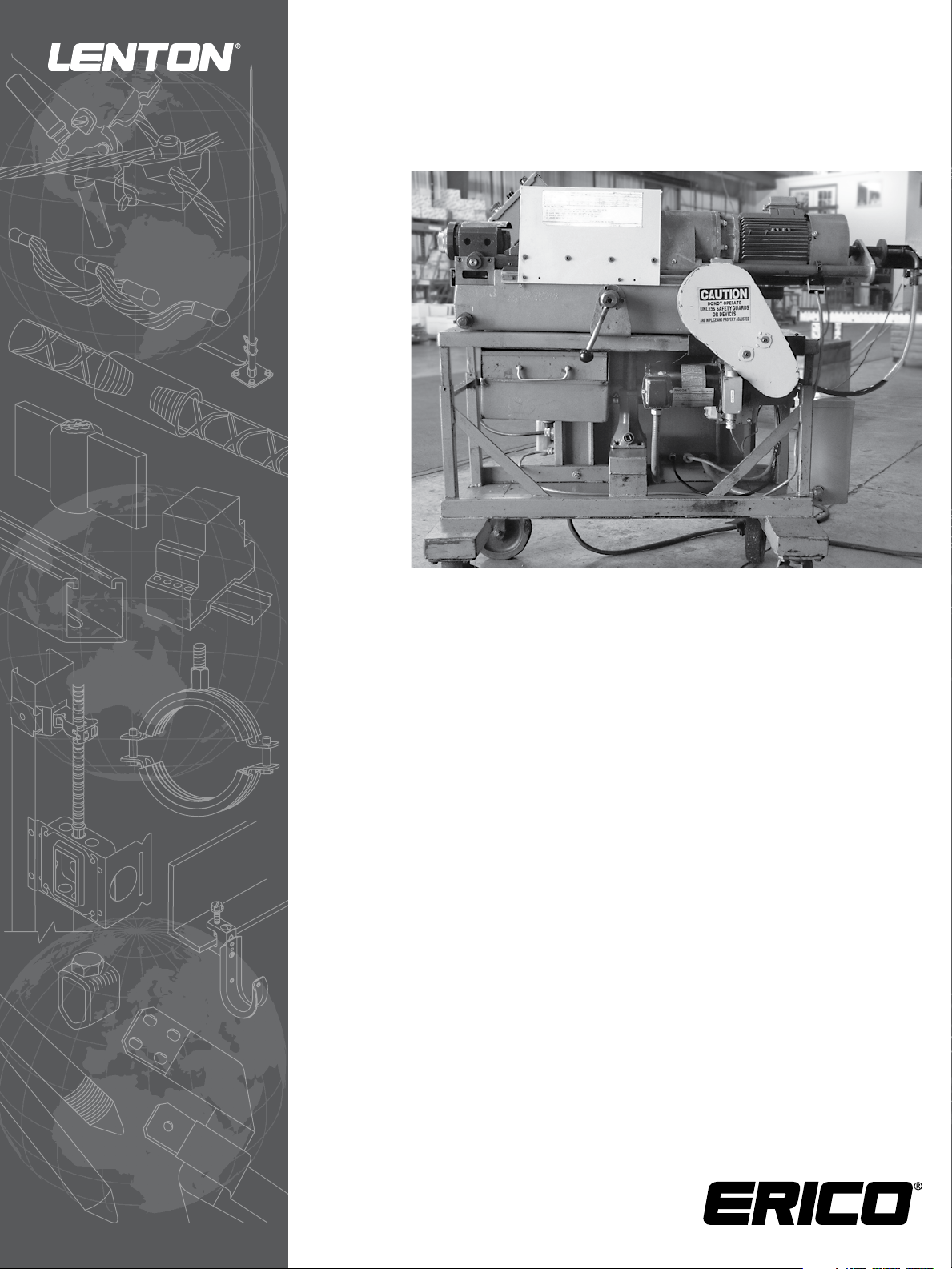
Machine Overview
Operator
Station
Impact
Wrench
Electrical
Control Panel
Threader – Front View
Outer Limit + Reference Sensors
(Normally Open)
Bar End
Adjustment
Cycle Start Sensor
(Normally Closed)
Step Down
Transformer
Threader – Control Panel Side
Threader – Side View
Spindle Proximity Switch
DC Motor
DC Proximity Switch
Kill Switch
www.erico.com
3
Page 4
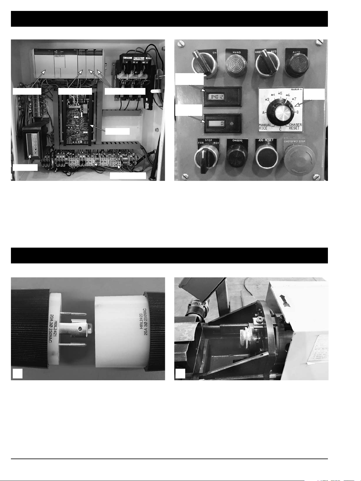
Machine Overview
Omron PLC Input Module
Introl 61F
Output Modules
DC Board
Cumulative
Counter
Bar Size
Selector
Counter
with Reset
Control Relays
Operator StationElectrical Control Panel
Electrical
1 2
The bar threader requires 220-240 volt, 3 phase power.
A four pronged plug (as shown) is standard.
After connecting the power be sure the head of the bar
threader is rotating in the direction indicated by the red arrow
on the hood. If it is not rotating in the correct direction,
switch any two of the power leads in the plug.
4
www.erico.com
Page 5
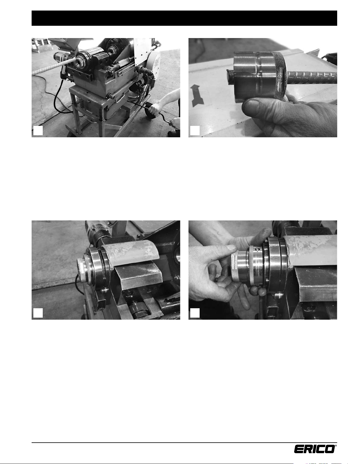
Center Rings
21
Adjust table height, with built in jack, to match elevation of
the bar.
To obtain the best centering of the rebar into the threading
machine, the best fitting set of center rings should be used.
We offer two or three different size sets per bar. To make
sure you are using the correct set, slide one of the center
rings per set over the bar ends to be threaded to determine
which one slides on easily with the least amount of slop.
Each center ring is stamped with the bar size it is to be
used with in millimeters.
The automated bar threader is capable of threading rebar
sizes # 3, # 4 (10M), # 5 (15M) and # 6 (20M).
www.erico.com
43
To change centers to a different bar size or to go with a set
that fits the bar better, push in the release ring and pull out
the existing center. Put in the new center and lock it in place
by letting loose of the release ring.
5
Page 6
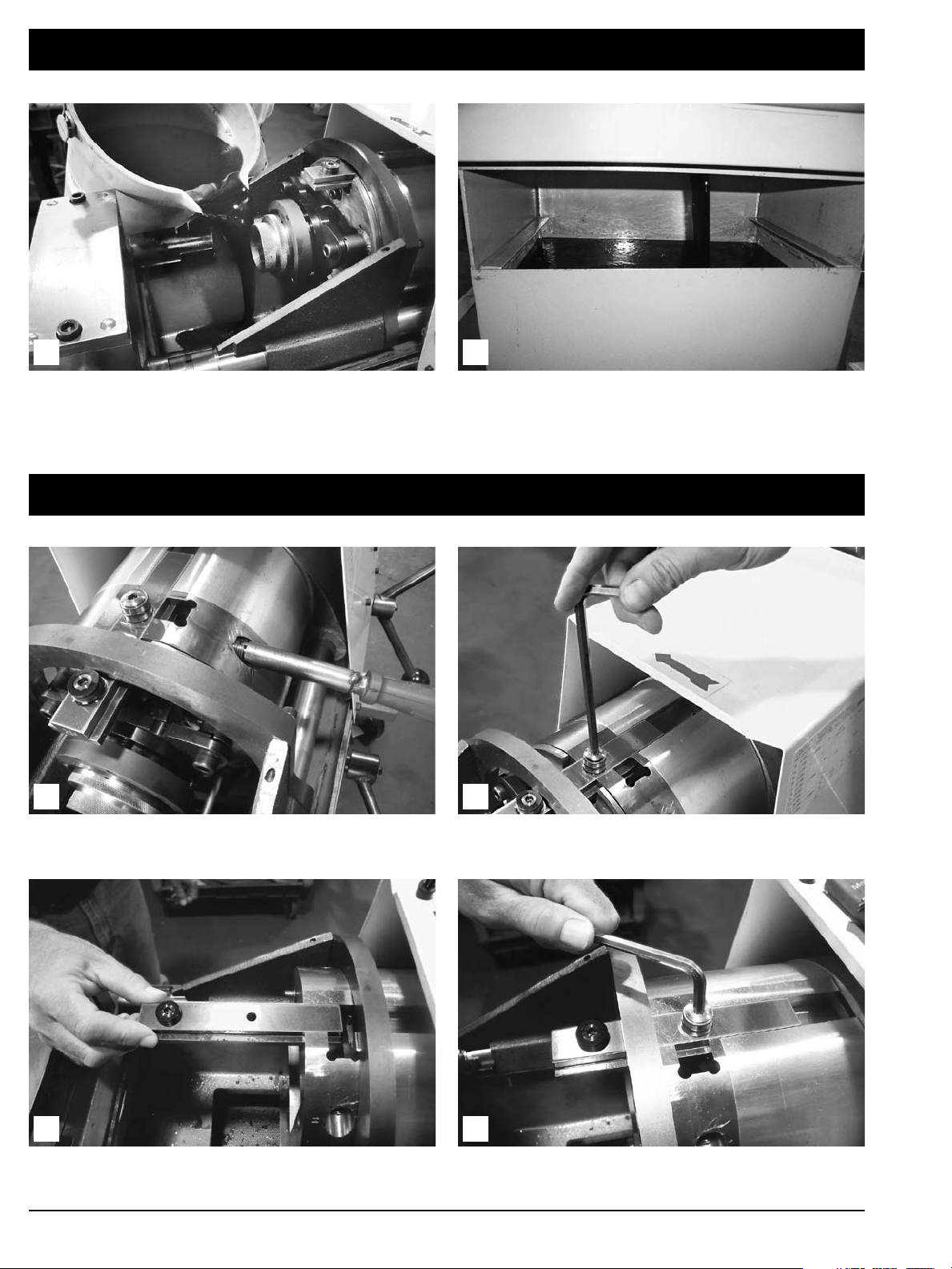
Add Oil
21
Prior to threading, the oil must be added. Pour the oil
onto the chip funnel and it will flow into the oil reservoir.
Only part #ELOIL should be used.
Change Control Key
To change the control key, remove the support rod screw,
compression spring, and the support rod from the head.
The reservoir is properly filled when the oil is just below
the chip drawer sliding brackets.
21
Loosen and remove the back bearing.
Slide the key out. Each key is marked with the bar size it is
to be used with in millimeters.
43
Slide in the new key and replace the spring, support rod and
support rod screw. Replace and tighten the back bearing.
6
www.erico.com
Page 7
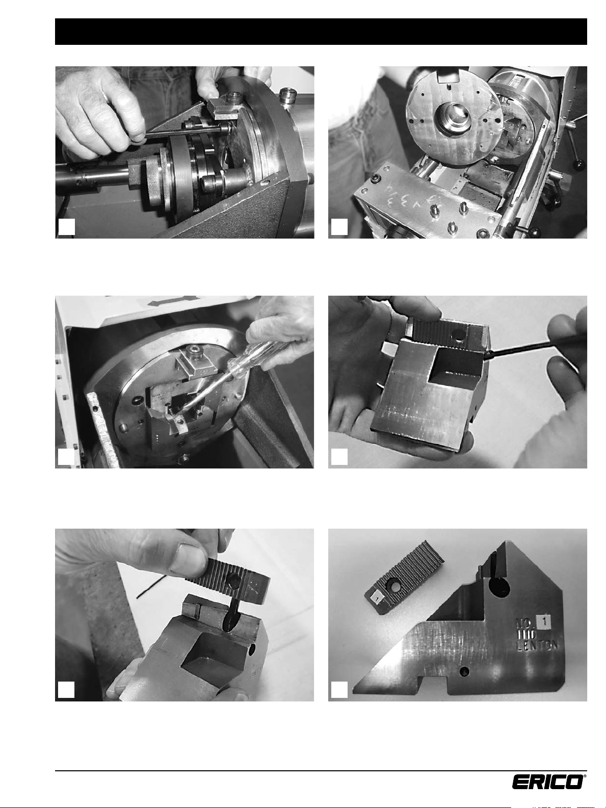
Change Chasers and Holders
21
Remove the face plate bolts with a 6 mm hex wrench. Three bolts hold it in place.
43
Remove the holders from the cutting head.
Loosen the set screw with a 3 mm hex wrench as shown above.
65
Remove the chaser from the holder. Chasers and holders have matching numbers.
The number 1 chaser goes into the number 1 holder, etc.
www.erico.com
7
Page 8
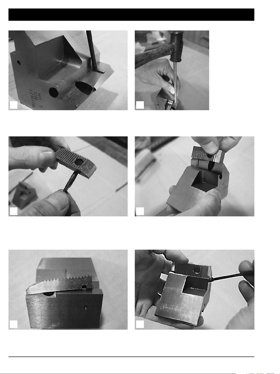
Change Chasers and Holders
87
Before installing the chasers make sure the woodruff key
(ELMP223) is tight. Press on both ends of the woodruff key
with an allen wrench, it should not move.
9
Take the hold down pin (ELMP203PIN) and place it through
the hole of the chaser as shown above.
To replace a woodruff key, set the key into the slot
by hand and drive into position using a hammer
and punch.
10
Insert the chaser pin into the top hole of the holder and push
down, making sure that the woodruff slot aligns with the
woodruff key, until the chaser sits completely flush on the
holder shelf.
11
This is what a chaser looks like when it is installed correctly
onto the holder.
12
After the chaser is installed correctly on the holder, hold the
chaser in place while tightening down the set screw against
the hold down pin.
8
www.erico.com
Page 9
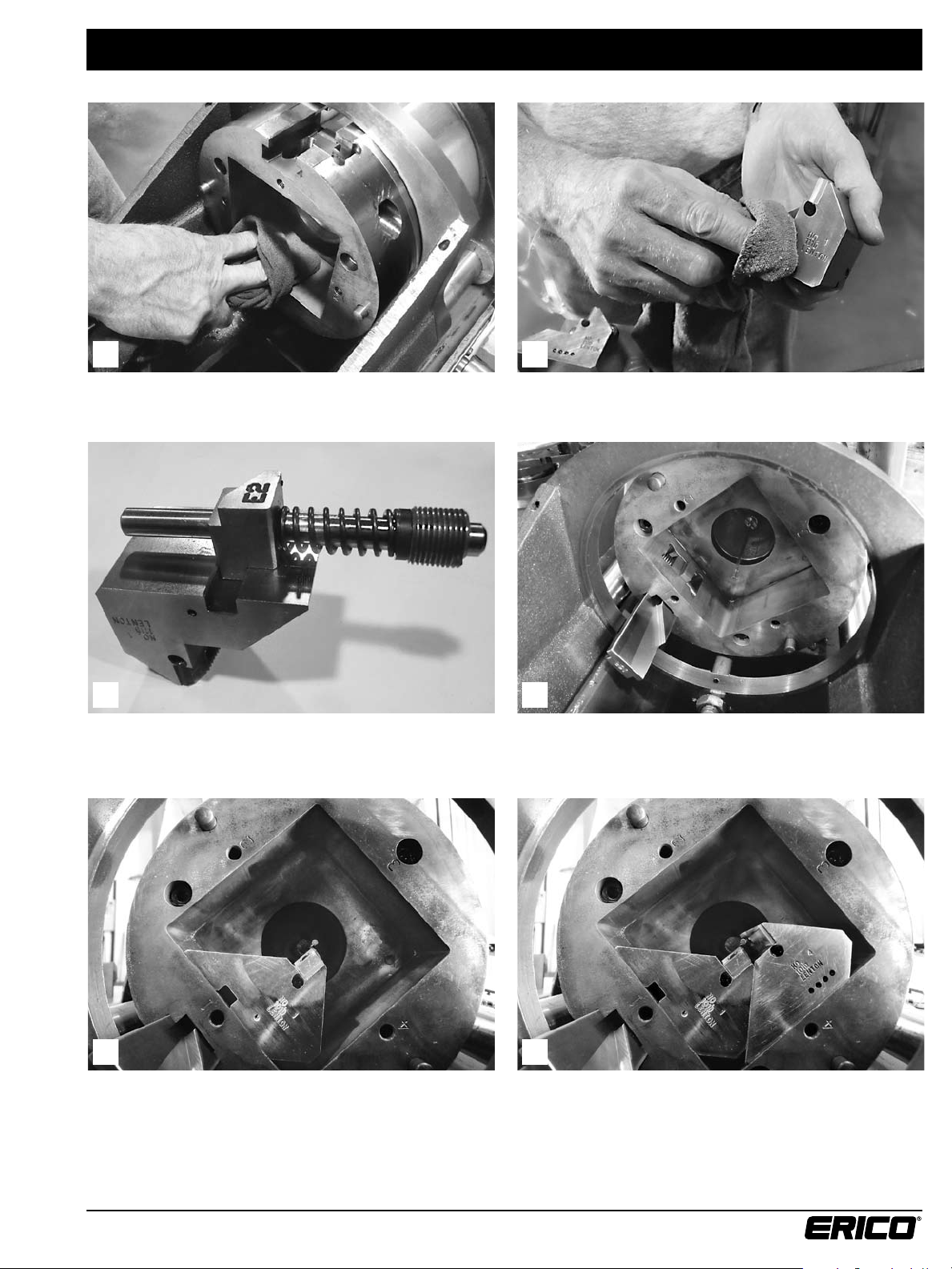
Change Chasers and Holders
1313
Before replacing the holders make sure the cavity in the head and the holders are clear and free of chips.
Wipe all flat surfaces with a clean rag.
1414
The number 1 holder (with the slot in it to accept the control
block) must be replaced first, then followed by holders #4, #2
and #3.
Rotate the cutting square until the control key is in the
position as shown above.
1414
Step 1 – Insert holder #1 as shown. Step 2 – Slide holder #4 into position.
www.erico.com
9
Page 10

Change Chasers and Holders
14
Step 3 – Slide holder #2 into position.
#3
#2
#4
#1
15
After the holders have been installed in the cutting square,
check that the numbers on the face of the holders match the
corresponding numbers on the face of the cutting square.
14
Step 4 – Slide holder #3 into position.
16 16
After installing the chaser holders, check to see that they do
not protrude outside of the cutting head. This would prevent
free holder movement during threading. If any do protrude
outside, remove them and reclean the head and holder(s).
Also look over the holder for any burrs that might need
taking down with a stone.
Stone the flat surfaces in the cutting square.
10
www.erico.com
Page 11

Change Chasers and Holders
1616
Stone the flat surfaces on the chaser holder. Stone the cover plate.
Attaching the cover plate assembly.
1717
After the holders are installed into the head correctly, wipe
off the face plate and fasten it to the head using the 6 mm
hex wrench.
www.erico.com
11
Page 12

Change Control Block
21
To change the control block, remove the face plate. Three bolts hold it in place.
Remove the chaser holders from the cutting square as
shown above.
Position the new control block as shown. Replace the
support rod, spring, and screw. The support rod goes
through the hole in the control block.
43
To remove the control block loosen the support rod screw
and pull out the support rod and spring. This will free the
control block and allow it to fall down.
65
Before replacing the chaser holders make sure the cavity in
the head and the holders are clear and free of chips.
12
www.erico.com
Page 13

Change Control Block
7
Wipe the holders clean of any chips and contaminants. The number 1 holder (with the slot in it to accept the control
8
After the holders have been installed in the cutting square,
check that the numbers on the face of the holders match
the corresponding numbers on the cutting square face.
7B
block) must be replaced first, followed by holders 4, 2 and 3.
9
Push the holders all the way against the back of the head
and check to make sure they do not protrude outside the
head. This would prevent free holder movement during
threading. If any holders do protrude outside, remove them
and reclean the head and holder(s). Also look over the holder
for any burrs that might need taken down with a stone.
10
After the holders fit into the head correctly, wipe off the
face plate and fasten it to the head.
www.erico.com
13
Page 14

Initialization of PLC
1. Turn power switch to the ON position
2. Confirm that the machine is in HAND mode.
Amber light will be on.
3. Turn the bar size selector switch to the ‘A’ position –
Special Adjustment Code.
Reference Proximity Switch
Outer Limit
Proximity Switch
Target
Bar Size Switch in the A position Manually triggering the reference and out limit proxes
4. Using the Forward/Reverse switch manually position
the transmission such that the target is positioned
between the reference and outer limit proximity
switches (see accompanying photo).
In the photo above, the proximity switches have been
triggered using a standard set of feeler gauges.
The threading machine is now ready for the SET-UP
procedure.
5. Manually trigger both the reference and the outer
limit proximity switches. The top of the proximity
switches will shine amber when they have been
triggered (see accompanying photo).
6. With both proximity switches triggered, depress the
JOG button. Initialization is verified by the simultaneous
flashing of all three lights (amber, green, and blue) on
the operator station.
14
www.erico.com
Page 15

Set-up Procedure
A set-up is required when changing from one bar size
to another, the cutting head is out of position relative
to the bar size selected or immediately following a
PLC Initialization (see preceding section).
A required set up is indicated by the following
conditions:
1. Auto Mode selected
2. Green Auto light is lit
3. Amber light is flashing
4. Cutting head will be spinning
Use the following procedure to set up the automatic threader:
1. Confirm that the bar size selected is correct.
2. Remove any rebar from the vice.
3. Depress the JOG/RESET button to begin the set up
procedure. NOTE: the amber light will remain lit during
the entire set up procedure.
4. Cutting head will stop spinning
5. Carriage will reverse until the outer limit proximity switch
contacts the target.
6. Unit will then change direction and move forward until
the reference proximity switch contacts the target.
7. Carriage will then reverse direction until the outer limit
proximity switch rests on the target.
8. At this point all motion stops.
9. Cutting head starts spinning again and the amber light
drops out and green auto light remains lit.
The machine is now in position and ready to thread a bar.
Confirm that the cutting oil is flowing.
www.erico.com
15
Page 16

Threading Operation
Cycle Start
Proximity Switch
21
1. Prior to threading the rebar, ensure that the step drum is
in the forward position – if not move the ring handle to
the forward most position (# 3 position on the step drum).
2. Load the rebar to be threaded into the front guide ring,
through the vice jaws and into the second guide ring
until you feel the bar stop up against the touch probe.
3. Begin the threading operation by pushing the touch probe
back with the end of the bar. This will activate the cycle
start proximity switch. At this time the vice will close and
tighten on the bar.
3
4. The machine will rapid forward a short distance – just
short of the end of the rebar – and then go into a
controlled feed forward.
5. Once the bar is engaged by the cutters (chasers) the
threading process begins. The machine continues forward
threading the bar.
6. Just before the threading cycle reaches full forward
stroke, the chaser holders will release from the bar with
a popping sound.
7. As the machine begins to retract, the vice will open
releasing the bar.
8. The machine will rapid in reverse until the outer limit
proximity switch contacts the target and motion
will cease.
9. The threader is now in position to repeat the
threading cycle.
Remove the bar from the threader and check the thread
length with the correct bar end gauge and thread profile
using a chaser.
16
www.erico.com
Page 17

Checking Threads and Bar End Engagement
Maximum
thread length
Minimum
thread length
21
The thread profile should be checked with a brand new chaser. To check the length of the thread, slide the bar end gauge
over the bar and look to see if the end of the bar falls within
the step range of the gauge.
3
If the thread length of the bar is off, the adjustment screw
at the back of the motor is used to make up the difference.
Turning it in, (clockwise) decreases thread length while turning
it out, (counter clockwise) increases the thread length.
If the thread length is off, the proper adjustment can easily
be made by measuring the amount of protrusion from or
recession into the gauge.
Example: If the bar is protruding beyond the gauge by
1/8 inch you would turn the adjustment screw in (clockwise)
so that the touch probe would move forward 1/8 inch.
If the bar was 1/8 inch too short you would turn the screw
out (counter-clockwise) moving the touch probe back
1/8 inch.
A scrap piece of bar should be used to set the bar end
gauge prior to making a production run.
www.erico.com
17
Page 18

Special Topics
Touch Probes
The touch probe is threaded into the end of the coolant
tube and is used during the cycle start operation. The probe
assembly consists of the following parts :
1. EL188F1 - Threaded Bushing (Left Hand Thread)
2. EL188F3 - 3/16 probe (for # 6 bar)
3. EL188F4 - 1/64 probe (for # 4 and # 5 bar)
4. A930H022 - Spring Pin (used with the 7/64 probe only)
A930H022
Spring pin
7/64 pin
Touch Probe with 7/64 pin
The 7/64 dia. probe is recommended for use with # 4 and # 5
rebar while the 3/16 pin is for use with # 6 bars.
Threaded Bushing - LH Thread
To remove the touch probe assembly from the coolant tube,
slide the special tool (EL188R) over the end of the touch
probe and align the slots. Turn clock-wise (Left Hand Thread)
until the bushing falls free of the coolant tube and pull the
assembly out with the special tool.
Touch probes are normally replaced when the probe
becomes bent or broken. To assemble a touch probe follow
the instructions that follow. To reinstall, follow the same
procedure as removing. Just remember to tighten the probe
by turning the special tool counter-clockwise.
To assemble the touch probe, start the end of the probe into
the front of the threaded bushing (opposite the threaded
end). Place the tip of the probe on a hard surface and lightly
hammer the bushing down onto the pin until you feel the
bushing and pin lock into position.
18
www.erico.com
Page 19

Special Topics
Vice Collars
Gap between threaded collar and the vice retaining plate
When assembling the vice collars, ensure that a small gap
remains between the collars and the vice retaining plate.
The gap allows for the free movement of the vice assembly.
Failure to maintain the gap will result in restriction of vice
jaw movement during the threading cycle. The jaws will
stutter and hesitate while trying to open or close. Adjust
the gap to compensate.
www.erico.com
19
Page 20

Special Topics
Kill Switch Adjustment
Kill Switch Assy.
The kill switch is employed to prevent a run-away situation
which could result in damage to the automatic threader.
The kill switch is wired in series with the emergency stop
and results in an immediate loss of power upon activation.
The kill switch utilizes a roller ball plunger assembly that is
situated to run on a track located on the fan cover at the
rear of the machine. When the roller ball head runs off of
the track the machine shuts down.
Use the following steps to set up or adjust the
kill switch assembly:
Kill Switch Adjustment and Set Up Procedure
1. Run a set up (reference section on the set-up procedure).
Track Ramp
2
2. After the set up is completed, position the kill switch
assembly so that the roller ball is on the edge of the
roller track ramp.
3. Depress the roller ball head (by pushing UP on the switch)
until the switch contacts are made. Listen for a distinct
clicking sound.
4
4. Hold the switch assembly in position and tighten the
screw on the collar.
Kill switch adjusted to the correct position
20
www.erico.com
Page 21

Special Topics
DC Board Trim Pot Adjustment
Before installing or replacing the DC control board, inspect the trim pots
to verify that they are adjusted as shown below.
SPEED / TORQUE
RESPONSE
Set to full clockwise
ACCEL / DECEL
Set to full clockwise
Set to full
counter-clockwise
Also confirm that the voltage is set
for 120 volts.
Voltage designation
Introl 282-CH DC board
www.erico.com
21
Page 22

Maintenance
21
Machine chips are caught in the screened drawer above the
oil reservoir. The drawer should be emptied as required during
the machining run and at the end of the day.
The oil is drained by loosening and removing the drain plug
at the bottom of the oil reservoir. A bucket and crescent
wrench is provided to accomplish this.
Let the oil sit in the bucket overnight to allow the metal
fines to settle out. Next morning, slowly pour the oil back
into the bar threader and clean out the bucket.
At the end of each day 15 minutes should be put aside to
drain the oil and clean out the oil reservoir.
3
After the oil is drained, a piece of cardboard or putty knife
can be used to scrape the chips out of the oil reservoir.
22
www.erico.com
Page 23

Troubleshooting
1. If the threader will not power up in hand mode,
check the following:
a. Check that the machine is plugged in and the
main disconnect is on.
b. Check to see if the E stop is activated.
c. See if the kill switch is activated.
d. The correct electrical power must be used.
See “Electrical” section.
2. If the cutting head does not spin in auto mode,
check the following:
a. Safety hood must be all the way forward.
b. Check motor control relay and corresponding fuse.
3. If the cutting oil is not flowing to the cutting
head, check the following:
a. Check control relay and the corresponding fuses.
b. Chips jamming the impellor.
c. Oil level – see “Adding Oil” section.
d. Possible build up of chips behind the
touch probe assembly.
4. If the chasers are wearing prematurely,
check the following:
a. Improper oil flow.
b. Harder than normal rebar.
c. Improperly prepared bar ends.
5. If the bar ends have stripped threads,
check the following:
a. Are the chaser holders in the correct position –
see “Change Chasers”.
b. Are the woodruff keys tight in the slot –
see “Change Chasers”.
c. Chaser wear.
d. Incorrect controlled feed speed –
check Introloc 61f.
6. If the chaser holders will not shift in the
cutting head, check the following:
a. Chips, dirt or other contaminants in the
cutting head.
b. Bent control rod.
c. Damaged control key.
d. Damaged control block.
e. Chaser holder(s) protruding beyond face of
cutting square.
7. If the bar ends suddenly become too long,
check the following:
a. Check that the tip of the touch probe
is not broken.
Operator Reference Chart
Bar Size
#3 (10M)
#4 12 (12A) 12XX (12D) 12XXXX (12E) ELBEG12A
#5 (15M) 16 (16A) 16X (16B) 16XX (16C) ELBEG16A
#6 (20M) 2.00MM 3/16 111D + “E” + Blue 20 (20A) 20 (20A) 20X (20B) ELBEG20A
Setup Instructions
1. Install proper tooling for desired bar size. See table above.
2. Rotate the bar selector switch to the desired bar size.
3. Close safety hood, and rotate Hand/Auto switch to Auto.
www.erico.com
Chaser
Pitch
1.25MM 7/64
Touch
Probe
Chaser Holder
Cam Block
101D + “E” + Blue
( 75 / S / 1 / 1 / B )
Release Spring
10 (10A) 10X (10B) 10XX (10C) ELBEG10A
4. Depress Jog/Reset button to setup for selected bar size.
5. Insert rebar into machine to start threading.
Note! Contact ERICO if further instructions are required.
23
Key
Guide Rings
Small Medium
Bar End Gauge
ELLBL39 A
Page 24

Appendix 1 — Light Codes
ELAT100 Operator Light Codes (Adjustments)
Hand Mode (Special “C” Adjust Code)
• Selected for vise close time adjustment
• Use Fwd and Jog to increase time by 0.1 second
• Use Rev and Jog to decrease time by 0.1 second
Note! The Auto light will illuminate when adjustments are made.
The factory default setting for closing the vise is 1.0 second.
The maximum allowable adjustment is +/- 0.5 seconds.
Hand Mode (Special “A” Adjust Code)
• Selected for initialization of PLC
• Must manually set both ref and out-limit prox probes
and depress Jog button
When initialization is on all lights will flash rapidly.
Warning! Manually position cutting head to ensure that
the target for the ref and out-limit prox probes is positioned
between them. Select for proper bar size, auto mode run a
setup to complete initialization.
Operator Light Key
Not illuminated Flashing Illuminated
Hand Mode (Special “B” Adjust Code)
• Selected for forward stroke adjustment
• Use Fwd and Jog to increase stroke by .04” (1 mm)
• Use Rev and Jog to decrease stroke by .04” (1 mm)
Note! The Auto light will illuminate when adjustments are made.
The maximum allowable adjustment is +/- 0.2”.
Warning! The above special adjustments are to be used only when authorized by a factory trained service technician.
Failure to follow these instructions may result in machine damage.
24
www.erico.com
Page 25

Appendix 1 — Light Codes
ELAT100 Operator Light Codes (Auto)
Auto Mode (Standard Code)
• Safety hood must be closed
• Use Fwd and Rev to manually operate vise
• Insert rebar to engage touch probe to start
threading cycle
Auto Mode (Setup Required Code)
• Must reset for selected bar size
• Ensure bar size selection is correct and depress
Jog/Reset button to start setup
The Hand light will remain lit when threader is in setup.
A setup is required when selecting a different bar size
or when the cutting head is not in the proper position
to start a threading cycle.
Auto Mode (in Cycle Code)
• Auto light will ash when in threading cycle
• Use Fwd to tighten vise if required
• Insert next rebar when cycle is completed
www.erico.com
Auto Mode (Worn Chaser Code)
Worn chaser warning!
Replace chasers as soon as possible.
• Ref Hand Mode instructions for resetting
chaser wear counters.
25
Page 26

Appendix 1 — Light Codes
ELAT100 Operator Light Codes (Hand)
Hand Mode (Standard Code)
• Machine can turn on only when in this mode
• Use Fwd/Rev switch to move cutting head
• Select Manual Vice to operate vise
Use Fwd to close, and Rev to open
• Jog head with Jog button and hood closed
• Select Auto Mode with safety hood closed
Hand Mode (Bad Option Code)
Bar selector switch is positioned in an area where no
options are available.
Hand Mode (Special Option Code)
Bar selector switch is in a Special Option area.
Return to a valid bar size to stop flashing chaser light.
In this option you may manually operate the vise,
or reset the chaser wear counters.
Hand Mode (Worn Chaser Code)
Worn chaser warning!
Replace chasers and reset chaser counter by positioning
the bar selector switch to Chaser Reset, open safety hood
and depress the Jog/Reset button. The Auto light should
illuminate, and the Chaser light should return to a normal
flash condition.
Note! When resetting the Chaser Wear counter, the last bar threaded,
1.25 mm or 2 mm, will be the counter that is reset.
26
www.erico.com
Page 27

www.erico.com
27
Page 28

www.erico.com
AUSTRALIA
Phone 1-800-263-508
Fax 1-800-423-091
BELGIUM
Phone 0800-757-48
Fax 0800-757-60
BRAZIL
Phone +55-11-3623-4333
Fax +55-11-3621-4066
CANADA
Phone +1-800-677-9089
Fax +1-800-677-8131
CHINA
Phone +86-21-3430-4878
Fax +86-21-5831-8177
DENMARK
Phone 808-89-372
Fax 808-89-373
FRANCE
Phone 0-800-901-793
Fax 0-800-902-024
GERMANY
Phone 0-800-189-0272
Fax 0-800-189-0274
HUNGARY
Phone 06-800-16538
Fax +39-0244-386-107
INDONESIA
Phone +62-21-575-0941
Fax +62-21-575-0942
ITALY
Phone 800-870-938
Fax 800-873-935
MEXICO
Phone +52-55-5260-5991
Fax +52-55-5260-3310
NORWAY
Phone 800-100-73
Fax 800-100-66
POLAND
Phone +48-71-349-04-60
Fax +48-71-349-04-61
SINGAPORE
Phone +65-6-268-3433
Fax +65-6-268-1389
SPAIN
Phone 900-993-154
Fax 900-807-333
SWITZERLAND
Phone 0800-55-86-97
Fax 0800-55-96-15
THAILAND
Phone +66-2-267-5776
Fax +66-2-636-6988
UNITED ARAB
EMIRATES
Phone +971-4-881-7250
Fax +971-4-881-7270
UNITED KINGDOM
Phone 0808-2344-670
Fax 0808-2344-676
CHILE
Phone +56-2-370-2908
Fax +56-2-369-5657
Copyright ©2011 ERICO International Corporation. All rights reserved.
CADDY, CADWELD, CRITEC, ERICO, ERIFLEX, ERITECH, and LENTON are registered trademarks of ERICO International Corporation.
HONG KONG
Phone +852-2764-8808
Fax +852-2764-4486
NETHERLANDS
Phone 0800-0200-135
Fax 0800-0200-136
SWEDEN
Phone 020-790-908
Fax 020-798-964
UNITED STATES
Phone 1-800-753-9221
Fax +1-440-248-0723
IP8206_A C343IS11WWEN 0.03M1111
 Loading...