

Page 1
DINLINE ALARM RELAY (DAR)
INSTALLATION INSTRUCTIONS
1. PREPARATION
DANGER: Electrical shock or burn hazard.
Installation of this device should only be made
by qualified personnel. Failure to lockout
electrical power during installation or maintenance can
result in fatal electrocution or severe burns. Before
making any connections be sure that power has been
removed from all associated wiring, electrical panels,
and other electrical equipment.
CAUTION NOTES:
1. The installation of this device should follow all
applicable electrical codes, such as the National
Electrical Code.
2. Check to make sure line voltage does not exceed
DAR275V voltage ratings.
3. Follow all instructions to ensure correct and safe
operation.
4. Do not attempt to open or tamper with the DAR in
any way as this may compromise performance and
will void warranty. No user serviceable parts are
contained.
2. INTRODUCTION
Selected DSD, TDS & TDF DINLINE Surge Protection
Devices include status monitoring circuits which provide visual
status display of device capacity. They may also provide a low
voltage opto-coupler alarm output circuit that can be connect to
the DAR to provide potential free (Form C) change-over
contacts. The DAR alarm contacts may be used to provide
output to external alarm systems or remote monitoring circuits.
One DAR can be used per DSD/TDS/TDF opto-coupler alarm
or up to 16 DSD opto-coupler alarms can be connected in
series to the one DAR to provide a common output. It is
recommended that the DAR be powered from the same
power circuit that feeds the device(s) being monitored,
however the DAR can be powered from other circuits. This
allows for example, one DAR unit to be connected to separate
SPDs that are protecting a three phase circuit.
MODEL NUMBER
DAR 275V
Note. Depending upon the usage of the DAR output contacts,
failure of power to the DAR may be interpreted as a failure of
one or more of the SPDs being monitored. Visual inspection
of the DAR and SPDs status displays would determine this.
3. MOUNTING
The DAR is designed to clip to 35mm (top hat) DIN rails
(standard EN50022). Unless otherwise mechanically
restrained, use horizontal DIN rails with the DAR module
spring clips to the bottom and the label text the correct way up.
NOTE: The DAR must be installed in an enclosure or panel
that:
• prevents the DAR temperature from exceeding
131°F (55°C)
• provides adequate electrical and safety protection
• prevents the ingress of moisture and water
• allows DAR status indicators to be inspected
4. ELECTRICAL CONNECTION
The interconnecting wiring should:
• be of size #10 to #14 AWG (2.5mm² to 6mm²) solid or
stranded conductor.
• The wire insulation should be stripped back 5/16" (8mm).
• NOTE: Do not use greater than 9inlbs (1Nm) of torque
when tightening the terminals.
CONNECTION TO TELECOMMUNICATIONS NETWORKS
The DAR is approved for use in Australia where the alarm
contacts may be connected to private lines or building cabling
associated with the telecommunications network. NO direct
connection to the public switched network should be made.
www.erico.com Page 1 of 2
Page 2
DINLINE ALARM RELAY
Totransient
Toremotealarmcircui
t
s
LNE
(4-6mm)
Bundle/twisttogether
Keep as short as practical
NL
INSTALLATION INSTRUCTIONS
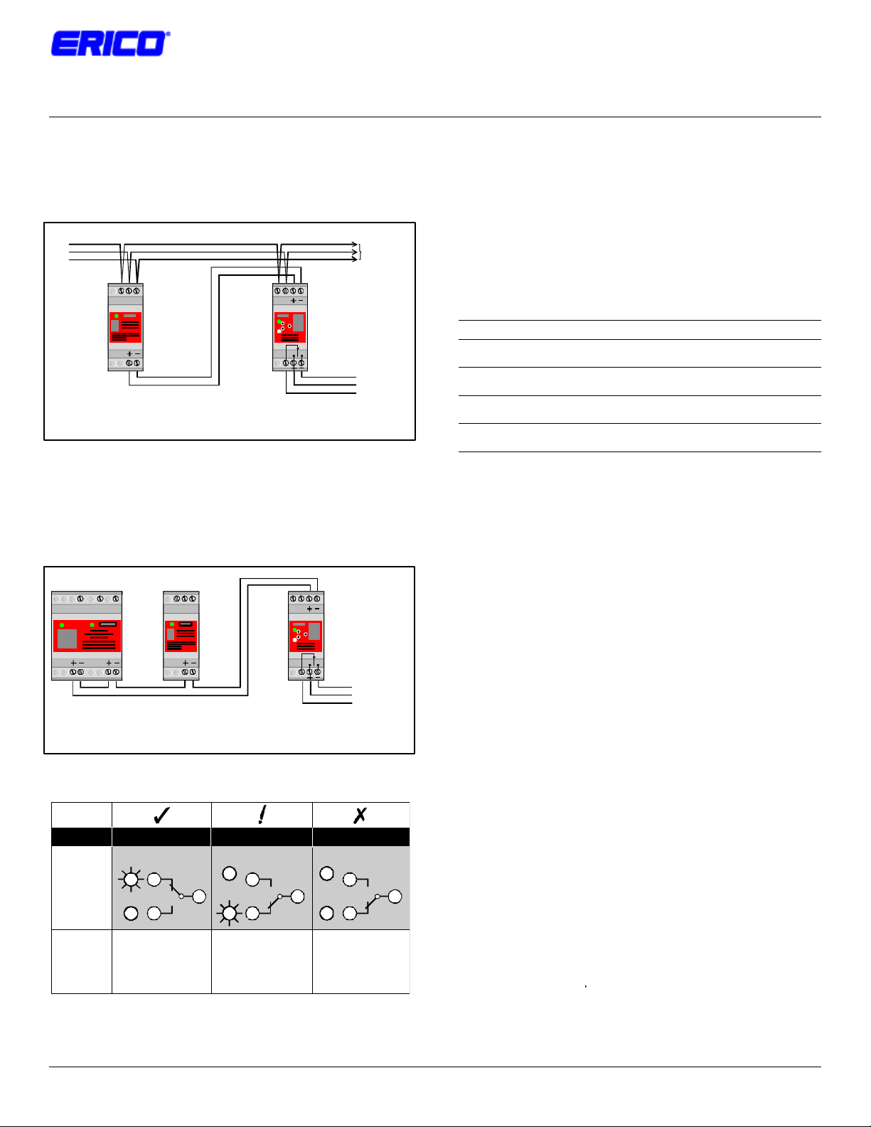
5. INTERCONNECTION
When connecting the DAR to a single opto-coupler output the
+ terminal of the SPD should connect to the + terminal on the
DAR. The – terminal should connect to the -- terminal.
protected
equipment
N EPh
DSD 2S/2T
Opto-coupler output
+/- terminal connections are polarity sensitive. Do not reverse.
When connecting the DAR to multiple opto-couplers the opto couplers should be connected in series with + terminal of one
connected to the – terminal of the next. The DAR + terminal
should connect to + SPD terminal at one end of the series
connection and the – DAR terminal connect to the – SPD
terminal at the other end of the series connection.
N EPh N EPh
NPh
DAR
Voltage free contacts
NPh
DAR
Voltage free contact
6. FUSING AND ISOLATION
Overcurrent protection must be installed in the upstream circuit
of the power supply to the DAR to provide protection to the
unit itself and the wiring in case of fault conditions.
The fuse rating should be based on the wiring size used to
connect to the DAR Ph & N terminals. Australian regulations
AS3000-1991, Table B2 specifies the following upstream
protection for single phase circuits, unenclosed in air.
Cable Size HRC Fuse or CB Rewirable Fuse
1.5mm2 16A 12A
2.5mm2 20A 16A
4mm2 25A 20A
6mm2 32A 25A
Where overcurrent protection of the appropriate rating or
smaller is already fitted in the upstream circuit, overcurrent
protection at the DAR will not be required
6. MAINTENANCE & TESTING
Before removing a DAR unit from service, ensure that the
power has been removed. Maintenance, testing and
replacement should only be undertaken by qualified personnel.
Testing of a DAR unit which is connected to a fully functional
DSD unit can be accomplished by removing power to the DSD
only. The DAR Status indication and output contacts should
alter from the Normal to Fault condition.
Upto16connections per DARmodule
+/- terminal connections are polarity sensitive. Do not reverse.
5. STATUS INDICATION
Testing of the DAR unit alone may be accomplished by
disconnecting the + / -connections to the unit. When power is
applied the DAR “Fault” Status Indicator should be illuminated.
By connecting the + / - terminals together, the “Normal” Status
Indicator should be illuminated. The output contacts should
alter to the appropriate state.
7. USE OF OTHER INTERFACES
STATUS
DISPLAY
EXPLANATION
Protection Operational
Normal
8
Fault
6
Normaloperation
Normal(green)indicatorON
Red indicatorOFF
Relayis energised
Power is supplied
4
Protection Alarm Fault Mode
Normal
8
Fault
6
DSDinalarmmodeorpower
toDSDhasbeenremoved
Normal(green)indicatorOFF
Red indicator ON
Relayisde-energised
Power is supplied
Normal
Fault
4
Power to DAR removed
Protectionstatusunknown
Normal(green)indicatorOFF
Red indicatorOFF
Relayis de-energised
Power is OFF
8
4
6
www.erico.com Page 2 of 2 Doc: HBCR1681, Rev: 1
Only DAR units are recommended for the interfacing of
equipment to the DSD, TDS & TDF opto-coupler alarm output
circuit(s). The direct connection of other equipment to these
opto-coupler alarm outputs may not provide sufficient isolation
or exceed the opto-coupler specifications. This may damage
the SPD and/or the connected equipment. Warranty may be
voided under such circumstances.
NOTE: In connecting to the SPD opto-coupler alarm
output(s), do not reverse the +/- connections as
damage may occur
Supply
See section 8for fusing details
 Loading...