

Page 1
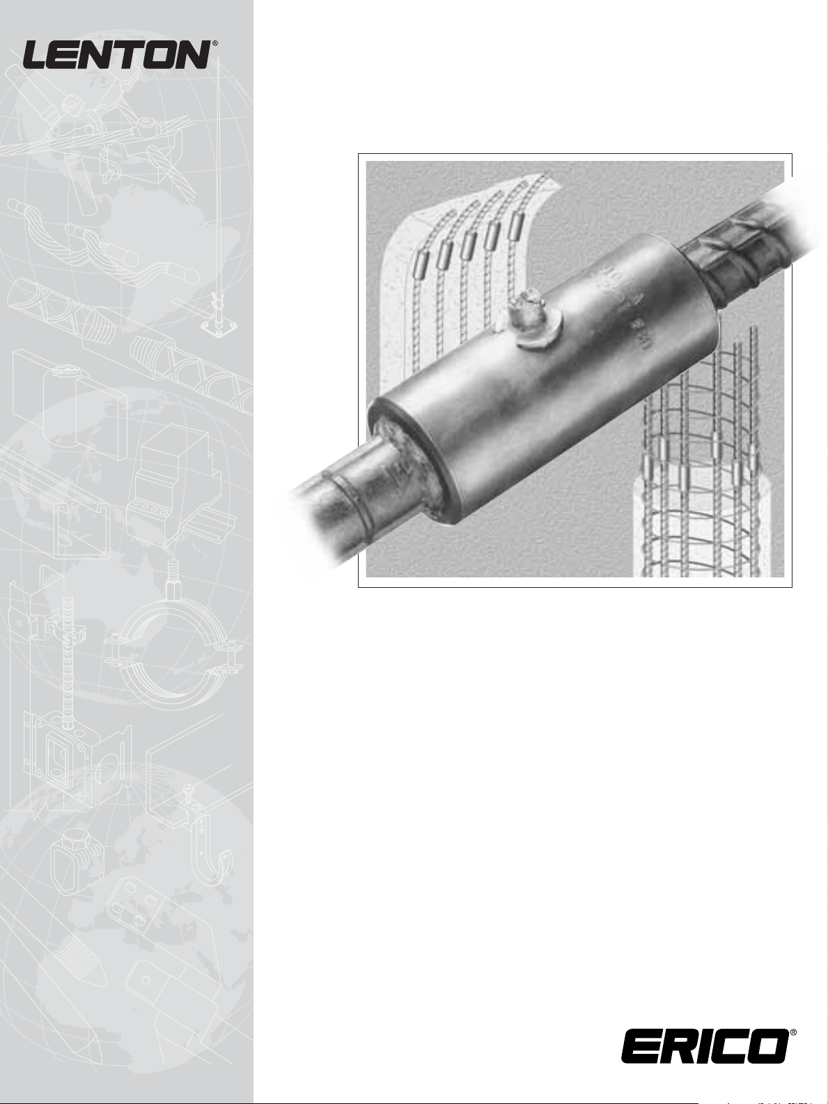
Instruction Manual
CADWELD®for Rebar Splicing System
Page 2

IMPORTANT
General and Safety Information
A. Only ERICO®manufactured equipment and materials should be used to make CADWELD®rebar splices.
1. Do not splice except as detailed in the instructions.
2. Do not use worn or broken equipment that could cause leakage.
3. Do not alter equipment or material without factory authorization.
4. Do not substitue for specified ERICO manufactured equipment and materials.
Failure to comply with the above may result in hazards to the individual, improper splices, or damage to items being spliced.
B.
Make splices in accordance with described splicing procedures and in consideration of surrounding conditions and personnel.
Refer to ANSI Z-49.1 SAFETY IN WELDING AND CUTTING and your local safety procedures.
1. Personnel should be properly trained in the use of this product.
2. Avoid breathing concentrations of smoke, as it may be hazardous to health.
3. Avoid contact with hot materials.
4. Advise nearby personnel of splicing operation in the area.
5. Remove or protect fire hazards in the immediate area.
6. Do not smoke when handling starting material.
C. Adhering to the recommended splicing procedures will minimize risk of burns and fire caused by hot molten material
spillage.
1. Make sure there is proper fit and assembly of equipment.
2. Avoid moisture and decomposable contaminants on splicing equipment and rebar.
Contact of hot molten metal with moisture or contaminants may result in spewing of hot material.
D. Unusual applications or conditions may exist which require special considerations.
1. Provide adequate ventilation where natural air flow is not sufficient to prevent personnel breathing concentrations of
smoke.
E. Storage of CADWELD filler material should be in a clean, dry, “No Smoking” area and should be restricted to access by
authorized personnel only.
1. Starting material and filler material are exothermic mixtures and react to produce hot molten materials with
temperatures in excess of 2200°C (4000°F) and a localized release of smoke. These materials are NOT explosive.
Ignition temperatures are in excess of 450°C (850°F) for starting material and 900°C (1650°F) for filler material.
2. In case of fire, water or CO
2
will aid in control of burning containers. Large quantities of water will aid in controlling
a fire should the exothermic materials become involved. Water should be applied from a distance.
F.
CADWELD filler material in the work area should be protected from spatter and hot materials to prevent accidental ignition.
Use a covered wood or metal gang box for storage of materials not for immediate use.
G. Dispose of slag from the CADWELD splicing process in a steel container that has a layer of dry sand in the bottom.
The sand is necessary to prevent burn through.
H. See splicing instructions enclosed for additional information.
Page 3

1
www.erico.com
Table Of Contents
General Safety Information...............….............................................................................IFC
Rebar Cleaning Procedure (Preparation) …………............................................................... 2
Instructions for Vertical Splicing (Bar-to-Bar) .................................................................... 3-4
Instructions for Horizontal Splicing …………....................................................................5-6
Filler Material Remixing and Placement Procedures............................................................. 7
Venting CADWELD
®
Horizontal Splices ……….................................................................... 8
Inspection …….................................................................................................................. 9
Eccentricity and Cocking of Rebars ……………................................................................. 9
Rejection of a Splice and Its Causes................…................................................................10
Void Limits.........................................................................................................................11
Additional Instructions for B-Series.................................................................................... 12
Welding of Splice Sleeves to Structural Steel......................................................................12
Care of Finished Assemblies...............................................................................................12
Addenda ...........…........................................................................................................... 13
External Bar Reference Marks ...........….............................................................................13
Bar End Gap ……..............................................................................................................13
B-Series Sleeve Repair........................................................................................................ 13
Tap Hole Relocation...........................................................................................................14
Use of Sleeves Out of Their Normal Position..................................................................... 15
Repair of Bar-to-Bar Production Splice Samples or Rejected Splices....................................15
Traceability....................................................................................................................... 15
Page 4
2
www.erico.com
Rebar Cleaning Procedure (Preparation)
1. Rebar ends to be spliced must be dry and free of
excessive rust, loose mill scale, dirt, paint, concrete, etc.
Clean back from bar end at least one-half sleeve length.
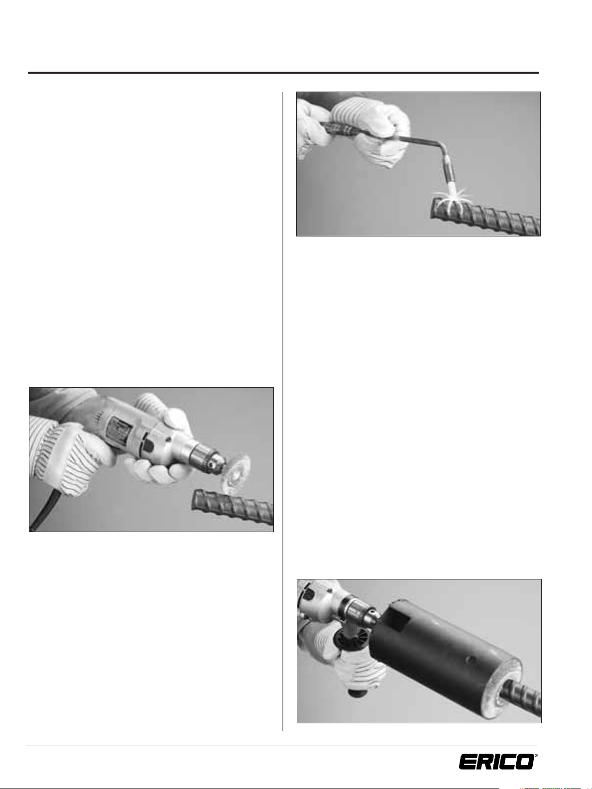
2. Cleaning Procedure
2.1 Torch and Power Brushing (See notes)
2.1.1 Flame dry ends to remove moisture and/or
burn away any other foreign contaminants.
Flame should be soot free and not leave any
residue or deposits on bar ends. A “rosebud”
torch tip is recommended.
2.1.2 Remove excessive rust and all loose mill scale,
dirt, paint, concrete, etc. with a power wire
brush.
2.1.2.1 Heavy duty, low speed (200-350 rpm),
reversible drill is recommended for
use with ERICO
®
brand of cleaning
brushes (Series RBW343). See catalog
for additional information.
2.1.2.2 1000 rpm or higher is recommended
for wire wheel and cup brushes
2.1.3 Repeat steps 2.1.1 and 2.1.2 on extremely bad
bar surfaces.
2.2 Torch and Sandblasting
2.2.1 Sandblast bar ends clean.
2.2.2 Flame dry ends to remove moisture.
Flame should be soot free and not leave any
residue or deposits on bar ends. A “rosebud”
torch tip is recommended.
2.3 Torch and Hand Wire Brushing
(See notes)
2.3.1 Flame dry ends to remove moisture and/or
burn away any other foreign contaminants.
Flame should be soot free and not leave any
residue or deposits on bar ends. A “rosebud”
torch tip is recommended.
2.3.2 Should lack of power or clearance restrictions
prevent the use of power-driven equipment,
remove excessive rust and all loose mill scale,
dirt, paint, concrete, etc. with a hand wire brush.
2.3.3 Repeat steps 2.3.1 and 2.3.2 on extremely bad
bar surfaces.
2.3.4 Wipe bar ends with a clean, dry rag to remove
any dust.
3. Badly deformed bar ends may require cutting to assure
easy fit of the sleeve. Bar end shear “drags” may be
flame cut or ground off. Oversize longitudinal ribs
should only be ground as flame cutting may damage the
bar, especially on higher strength steels. The longitudinal
ribs should not be ground below the height of the bar
deformations.
4. Cleaned bar ends that must be left out overnight should
be protected (use empty plastic filler material bags) and
must be re-dried and re-cleaned if necessary.
NOTES:
1. Brushes must be kept free of grease, oil, and/or
other contaminants that could evolve gas and
cause porosity in filler material.
2. Eye protection should be worn when using
power-driven cleaning brushes.
3. Do not reverse the rebar cleaning brush
while it is engaged with the rebar.
Page 5

3
www.erico.com
Instructions For Vertical Splicing (Bar-to-Bar)
1. Clean rebar ends as per “Rebar Cleaning Procedure”
on page 2, as required.
2.
Position bottom support clamp and end alignment fitting
so end of rebar will be at tap hole opening of sleeve.
“T” shaped support rod on bottom support clamp
should be in line with the sleeve tap hole so that
support will be directly beneath the pouring basin.
3. Place a double wrap of packing material into position in
the lower end alignment fitting. Using a blunt screwdriver,
place the first wrap around the bar into the space
between the bar and end alignment fitting. The second
wrap around the bar is placed loosely above the first.
4. Place splice sleeve into lower fitting and seat firmly
against the packing to seal lower end of sleeve.
5. Lower top rebar into position. The average gap
between bar ends should not exceed 1/4-in. (6mm).
If a natural gap is not provided by the shape of the
reinforcing bar ends, a spacer can be used.
Spacers are enclosed in an envelope in each carton of
CADWELD
®
ferrous filler material.
Both bar ends should be visible through the sleeve tap
hole.
6. Place a single wrap of packing material loosely around
bar on top of splice sleeve; DO NOT PACK.
7. Place end alignment fitting on top of splice sleeve;
position ceramic insert guide tube assembly firmly into
taphole, making sure it is completely seated inside the
hole.
8. Flame dry pouring basin and crucible before using.
As a check, a drop of water should boil off rapidly.
Page 6
4
www.erico.com
Instructions For Vertical Splicing (Bar-to-Bar)
9.
With pouring basin frame handles unlocked and pouring
basin slightly open, place the pouring basin around the
ceramic insert and against the splice sleeve. Close pouring
basin frame handles and lock. Place chain around the
sleeve and finger tighten thumb nut. Be sure to support
the pouring basin while securing chain to prevent
unseating of the sleeve against the bottom packing.
Adjust “T” shaped support rod against bottom of pouring
basin. Support rod should just touch and support levelled
pouring basin DO NOT force pouring basin up.
NOTE: A crucible should not be reused until allowed to
cool for 15 minutes or more. If more frequent use
is desired, several crucibles complete with frames
should be used alternately to allow sufficient cooling
time. Clean crucible thoroughly inside. Empty the
crucible completely, see Note 15 & 16 on this page for
additional information. DO NOT use a wire brush.
10. Place crucible ceramic insert assembly in bottom of
crucible. All crucibles use the same ceramic insert.
11. The crucible ceramic insert assembly is supplied with a
steel disk pre-installed into it as a one-piece assembly.
If the steel disk is not present in the ceramic insert,
place the steel disk on the crucible ceramic insert and
check for proper seating. Remix bag of CADWELD
®
filler
material
and fill crucible according to the instructions on
page 7.
12. Position crucible on the pouring basin and secure the
tiedown chain, keeping it just loose enough to allow
swivelling of the crucible without tipping.
13. Open the starting material container. Evenly distribute
the starting material over the filler material in the crucible,
saving a small amount to be placed on the tab of the
crucible extension. Place the crucible extension on the
crucible and put the remainder of starting material on
the tab. Place the crucible cover on the extension.
Standing off to the side of the opening and up wind,
ignite the starting material on the tab.
14. Keep the tiedown chain secured at all times.
Immediately after the sleeve has filled, slowly swivel
the crucible back and forth to break the slag between
the base of the crucible and top of the pouring basin.
Repeat after 15 or 20 seconds as necessary.
After the slag has solidified, release the tiedown chain
and remove the crucible. All other parts can then be
removed.
15. Clean the crucible by turning upside down and placing
a metal rod (#5 [16mm] rebar) against the ceramic and
lightly tapping the rod end to discharge the slag and
ceramic into a suitable waste container.
16. Break off riser with hammer. Clean slag from crucible
and pouring basin as soon as possible to promote cooling.
Use a whisk broom, rag or wooden wedge for cleaning.
Do not use a wire brush. Cover and crucible extension
need not be cleaned every time.
NOTE: Clean flash or debris from all mating surfaces as debris
can
cause springing of the equipment clamps and hinges.
Page 7

5
www.erico.com
Instructions For Horizontal Splicing
1. Clean rebar ends as per “Rebar Cleaning Procedure” on
page 2.
2. Slide splice sleeve over bar before placing rebar into
position for splicing.
The average gap between bar ends should not exceed
1/4-in. (6mm). If a natural gap is not provided by the
shape of the reinforcing bar ends, a spacer can be used.
The spacer is not required to remain in position.
Spacers are enclosed in an envelope in each carton of
CADWELD
®
filler material. For certain conditions, a
spacer may be omitted. Contact ERICO
®
for additional
information.
3. Position splice sleeve by placing tap hole directly in line
with the gap between the bar ends.
Lift the splice sleeve completely and drive down the
vent pins. The splice sleeve need not be concentric with
the rebar.
For sleeves without vent pins, please see page 8.
4. Place a double wrap of packing material around rebar,
against both ends of sleeve. The second wrap of packing
should be placed alongside the first. DO NOT force
packing into splice sleeve.
5. Place end alignment fitting around rebar. Lock and slide
into position against packing and sleeve. Be sure that
the fittings slide over the ends of the sleeve.
6. Place horizontal packing clamp in position. (Normally it
will hang from the rebar.) Draw bar must not block
access to the sleeve tap hole.
Tighten hand knob on end of clamp to draw end
alignment fittings firmly into position over sleeve ends.
This action wedges the packing against the sleeve and
rebar to prevent leakage of filler material.
7. Position ceramic insert guide tube assembly firmly into
tap hole, making sure it is completely seated in the tap
hole.
8. Flame dry pouring basin and crucible before using.
As a check, a drop of water should boil off rapidly.
9. Place pouring basin into position on the sleeve.
Place chain around sleeve and finger tighten thumb
nut. Do not over tighten thumb nut.
Spacer
Page 8

6
www.erico.com
Instructions For Horizontal Splicing
NOTE: A crucible should not be reused until allowed to
cool for 15 minutes or more. If more frequent use
is desired, several crucibles complete with frames
should be used alternately to allow sufficient cooling
time.
Clean crucible thoroughly inside. Empty the crucible
completely. See Note 13 & 14 on this page for
additional information. Do not use a wire brush.
Place crucible ceramic insert in bottom of crucible.
All crucibles use the same ceramic insert.
The crucible ceramic insert assembly is supplied with a
steel disk pre-installed into it as a one-piece assembly.
If the steel disk is not present in the ceramic insert, place
the steel disk on the crucible ceramic insert and check for
proper seating.
Remix bag of CADWELD
®
filler material and fill crucible
according to the instructions on page 7.
10. Position crucible on the pouring basin and secure the
tiedown chain. Keeping it just loose enough to allow
swivelling of the crucible without tipping.
11. Open the starting material container. Evenly distribute
the starting material over the filler material in the crucible,
saving a small amount to be placed on the tab of the
crucible extension. Place the crucible extension on the
crucible and put the remainder of starting material
on the tab. Place the crucible cover on the extension.
Standing off to the side of the opening and up wind,
ignite the starting materials on the tab.
12. Keep the tiedown chain secured at all times.
Immediately after the sleeve has filled, slowly swivel
the crucible back and forth to break the slag between
the base of the crucible and top of the pouring basin.
Repeat after 15 to 20 seconds as necessary. After the
slag has solidified, release the tiedown chain and remove
the
crucible. All other parts can then be removed.
13. Clean the crucible by turning upside down and placing
a metal rod (#5 [16mm] rebar) against the ceramic and
lightly tapping the rod end to discharge the slag and
ceramic into a suitable waste container.
14. Break off riser with hammer. Clean slag from crucible
and pouring basin as soon as possible to promote cooling.
Use a whisk broom, rag or wooden wedge for cleaning.
Do not use a wire brush. Cover and crucible extension
need not be cleaned every time.
NOTE: Clean flash or debris from all mating surfaces as this
causes springing of the equipment clamps and hinges.
Page 9

7
www.erico.com
Filler Material Remixing And Placement Procedures
1. Cut off top of bag just below closure tie. This will allow
enough remaining bag length to permit remixing.
2. Open bag and then reclose to entrap air. (Starting
material container may be removed if it is convenient.)
3. Fold over cut end of bag, leaving enough open space
within the bag to allow free tumbling of filler material.
4. Using both hands, flip-flop the bag several times,
allowing the filler material to remix.
5. Unfold bag and pour enough filler material into a
prepared crucible to completely cover the crucibleceramic and steel-disk assembly. Lift crucible up to
ensure filler material is not leaking. (If it is leaking,
carefully pour the filler material back into the bag and
reseat the steel disk or replace if bent.)
6. Dump the remainder of the filler material into the
crucible, taking care to remove the container of starting
material if it is still in the filler material.
Page 10

8
www.erico.com
Instructions For
Venting CADWELD
®
Horizontal Splices*
The use of wire or nails for venting is two-fold. Primarily,
they raise or lift the sleeve from the top of the rebar, creating a gap between the sleeve and bar. The gap is necessary
for proper fill at the top of a horizontal splice. Gravity takes
care of filling the bottom of the sleeve.
The second purpose of the wires or nails is to provide a
path for the escape of air from the inside of the sleeve.
During splicing, air inside the sleeve is greatly expanded by
the incoming molten metal. If this air is trapped in the
sleeve, it takes up volume and will not allow the metal to
fill correctly. Creating an avenue of escape (with the wires
or nails) allows the metal to adequately fill the splice sleeve.
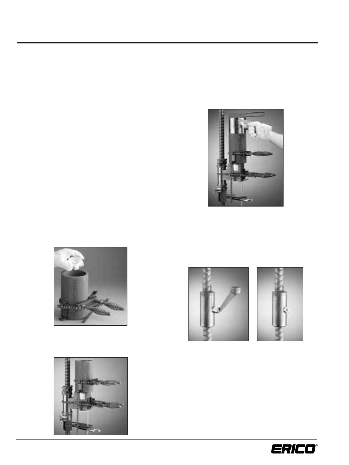
Venting with vent pins. Raise sleeve until it touches the
bottom of the bar and firmly drive down vent pins with a
hammer.
Venting with twisted tie wire. Place uncoated steel wire
on top of bar. Wire should be long enough to protrude
approximately 2-in. (50 mm) into sleeve and out beyond
End Alignment Fitting as shown above.
Venting with nails. Place uncoated steel nail on top of
bar. Nail should be long enough to protrude approximately
2-in. (50mm) into sleeve and out beyond End Alignment
Fitting as shown above.
Venting of B-Series structure splice with twisted tie
wire. Place uncoated steel wire on top of bar. Wire should
be long enough to protrude full length of sleeve and out
beyond End Alignment Fitting as shown above.
*Formerly Bulletin 101
Page 11

9
www.erico.com
Inspection
Inspection of a CADWELD®splice is a visual process.
Properly made splices will have filler metal visible at both
ends of the sleeve and at the Tap Hole.
Due to the gasket action of the packing, the filler metal will
not always flow to the very edge of the sleeve. This condition is most prominent in splices that require use of the
Horizontal Packing clamp which, when tightened, forces
the packing into the sleeve. The bottom of a vertical splice
will exhibit the same tendency due to the weight of the
equipment forcing the packing into the sleeve.
This indent caused by the packing will vary from 1/8-in.
(3 mm) to 1/4-in. (6 mm) in depth. Occasionally, where
a loose end of the packing has been forced into the sleeve,
the indent can vary from 3/8-in. (9.5 mm) to 1/2-in.
(12.7 mm) in depth. See Figures 1 and 2 for illustrations.
NOTES:
1. Do not manually force packing into sleeve. As described
above, the packing will be forced into the sleeve by
either the Horizontal Packing Clamp or by the weight of
the splicing equipment.
2. When making vertical splices, it is important that the
proper length packing be used at both the top and the
bottom of the sleeve. The longer bottom packing (2-1/2
wraps) is used to seal the bottom of the sleeve while the
shorter top packing (1-1/4 wraps) is loosely placed around
the top of the sleeve in order to permit expanding air to
escape and allow proper fill. Top packing should never
be forced inside the sleeve.
Due to the loose top packing, filler metal will often
flow above the top of the sleeve. This overflow is not
detrimental to the splice and should not be a cause for
rejection. In fact, an overflow is evidence of complete
fill. It is not necessary to remove filler metal flash
(collars) at the end(s) of the splice sleeves.
Adequate venting is essential for proper fill in all splice
positions. See page 8 for recommended
venting
procedures on horizontal splices.
3. When the riser is removed, a shrinkage bubble may be
exposed in the Tap Hole area. This bubble should not
be distinguished from general porosity and shall not
constitute cause for rejection.
Eccentricity And Cocking Of Rebars
If the splice sleeve is filled with sound metal, eccentricity,
cocking and contact of rebars within the sleeve will have
no effect on splice performance and are not cause for
rejection. Standard splicing procedures for horizontal splices
require lifting of the splice sleeve until contact is made with
the bottom of the rebar.
Figure 1
Figure 2
Filler Metal
Reinforcing Bar
Splice Sleeve
End Alignment
Fitting
Packing
Note How It Bulges Into
Opening Between Splice
Sleeve And Reinforcing Bar
(See Note 1.)
Spacer
Reinforcing Bar
Splice Sleeve
Filler Metal
Shrinkage
Bubble
(See Note 3.)
Page 12

10
www.erico.com
Rejection Of A Splice And Its Causes
Improper Fill
Filler metal not visible at ends of sleeve –
See “Void Limits.”
1. Filler metal leakage due to faulty use of packing or
misalignment of equipment.
2. Excessive gap between the ends of the rebars or
between the rebar end and the plate or structure to
which a B-Series splice sleeve is welded. (Requires more
filler metal to fill this space.)
3. Use of a smaller cartridge than called for or use of only
part of the correct cartridge due to spillage when loading.
4. Undersize rebar requiring more filler metal to completely
fill the sleeve. (Check the latest ASTM specification.)
5. Packing forced into the sleeve beyond the acceptable
void limits.
6. If rebars are not clean and dry, gas or steam will be
generated by the heat of the molten filler metal. This
gas or steam can cause a blowout or general porosity
and produce voids.
7. Improper placement of rebar ends in sleeve causing
blockage of incoming filler metal at the Tap Hole.
8. Inadequate venting of Splice Sleeve. For vertical splices
refer to Splice Kit Sheet for proper length of top packing
(approximately 1-1/4 wrap around top bar). See page 8
for recommended venting procedures on horizontal
splices.
9. Sound splices often have pin holes, shrinkage fissures
and cold joints. These are usually visible at the ends of
completed splices and are not cause for rejection.
Slag at Taphole
1. Omission of Steel Disk at bottom of Crucible.
2. Any one or more of items 1, 2, 3, and 4 under
“Improper Fill.”
NOTE: When checking for filler metal at the sleeve Tap
Hole, you cannot rely on color alone. When a hot
riser is broken off, the exposed filler metal will
oxidize almost immediately and discolor. If there is
any doubt as to whether filler metal or slag is present
in the Tap Hole, use a coarse file, prick punch or
hammer to test. Filler metal will shine while slag will
remain dull and crumble. Breaking off the riser may
pull metal out of the sleeve Tap Hole. This should
not be construed as an unfilled Tap Hole and is not
cause for rejection.
Blowouts indicate that the cleaning practice
for rebar ends should be reviewed
Power wire brushing and torch drying (as called for in
standard instructions “Rebar Cleaning Procedure”) will help
eliminate blowouts and severe voids.
Blowouts also can be caused by Splice Sleeves and other
equipment being damp. This most commonly occurs when
material is left out overnight or in the rain.
Page 13

11
www.erico.com
Void Limits
Splices shall be acceptable if the void per end does not exceed the limit listed below. Void areas
are approximated as shown in the illustrations below. More exact void measurements should be
made only when necessary.
SUMMARY
The inspection of a CADWELD®rebar splice is visual. Occasional checking of the workmanship of the splicer to make sure
that
he or she is following the correct splicing procedure will
serve to reinforce the judgement of the inspector on the job.
ERICO
®
standard instructions
should be consulted for additional information.
NOTES:
1. Allowable accumulative void
is shown for each end. For
example, a splice of #18 bar
in RBT-1891 is acceptable
with a spot void 1
1
/2-in.
(38.1 mm) wide, 1
1
/2-in.
(38.1 mm) deep, and 5/16-in.
(7.9
mm) low fill around
remaining
perimeter
of bar.
(Cumulative void are = 1.50
(1
1
/2 -5/16) + 7.09 (5/16 –
3/16) =
2.66 square inches
[17.2 cm
2
].)
The width (W)
of any void is
measured at
the bar perimeter.
There is a
3/16 in. (5 mm) allowance
for packing.
2.
Use this column for all
standard splices; vertical,
horizontal, horizontal side
fill, angled splices, and
B-series structure splices
with spot voids.
3. Use this column for vertical
splices only with low filler
metal around entire circumference (for spot voids, use
Column A). Applicable also
for vertical B-Series Structure
Splices with low filler metal
around entire circumference.
NOTE:
Void dimensions can be
established by use of a
probe of tie wire.
Bar Size Sleeve Number Allowable Void
Column A (1) (2) Column B (3)
Spot Voids Full Circumference Low
(in
2
) (cm2) (in) (cm)
#4 RBT5101A (HA) or RBB592JA 0.47 3.03 0.500 1.27
#5 RBT5101A (HA) or RBB592JA 0.53 3.41 0.500 1.27
#6 RBT6101A (HA) or RBB692JA 1.05 6.77 0.625 1.58
#7 RBT7101A (HA) or RBB792JA 1.03 6.64 0.562 1.42
#8 RBT8101A (HA) or RBB8101JA 1.02 6.58 0.500 1.27
#9 RBT9101A (HA) or RBB992JA 1.02 6.58 0.500 1.27
#10 RBT1091A (HA) or RBB1092JA 1.03 6.64 0.437 1.11
#11 RBT11101A (HA) or RBB11101JA 1.53 9.87 0.562 1.42
#14 RBT14101A (HA) or RBB14101JA 2.15 13.8 0.625 1.58
#18 RBT1891A (HA) or RBB1892JA 3.00 19.3 0.625 1.58
#6 to #7 RBT7101A (HA) 1.05 / 1.03 6.77 / 6.64 0.625 / 0.562 1.58 / 1.42
#7 to #8 RBT8101A (HA) 1.03 / 1.02 6.64 / 6.58 0.562 / 0.500 1.42 / 1.27
#8 to #9 RBT9101A (HA) 1.02 / 1.02 6.58 / 6.58 0.500 / 0.500 1.27 / 1.27
#9 to #10 RBT10901A (HA) 1.02 / 1.03 6.58 / 6.64 0.500 / 0.437 1.27 / 1.11
#10 to #11 RBT11101A (HA) 1.58 / 1.53 10.1 / 9.87 0.625 / 0.562 1.58 / 1.42
#11 to #14 RBT1114101A (HA) 1.53 / 1.52 9.87 / 9.80 0.625 / 0.625 1.58 / 1.58
#11 to #18 RBT1118101A (HA) 1.53 / 1.99 9.87 / 12.8 0.562 / 0.500 1.42 / 1.27
#14 to #18 RBT1418101A (HA) 2.15 / 1.99 13.8 / 12.8 0.625 / 0.500 1.58 / 1.27
= T-Series and B-Series = T-Series Transition
Void Limits
Page 14

12
www.erico.com
Additional Instructions For B-Series
1. Leave protective wrappers on sleeves until ready to arc
weld.
2. When removing protective wrappers, avoid tearing as
wrappers must be inserted in sleeves after welding and
before caplugs are installed as shown.
3. Cut or fold protective wrapping paper same length as
the sleeve (splice sleeve original wrapping.)
4. Insert paper into sleeve with unprinted side out.
5. Place O.D. sleeve cap caplug over sleeve and tap hole
caplug in tap hole (and vent hole plug in vent hole if
required). See table in catalog for proper part number.
6. Caplugs must be kept tightly in place until removed for
splicing bar in sleeve.
7. As an additional precaution against moisture, it is
suggested that polyethylene sheet, tarpaulins, building
paper or other protective cover be used to cover sleeves
after welding and until they are spliced.
8. If CADWELD
®
splicing of the welded assembly will not
occur for a week or more, it is recommended that the
metal O.D. end cap be placed over the end of the sleeve
and secured with all weather pipe tape to hold it in
position. The metal end cap will protect against dislodging
or puncturing of the plastic O.D. caplug.
9. When ready to complete the connection of rebar to the
sleeve, remove end caps, plugs, paper and flame dry
sleeve thoroughly.
NOTES:
1. O.D. sleeve cap caplug, tap hole caplug, and paper must
be placed in sleeve as soon as sleeve has cooled after
welding to effectively prevent internal rusting.
2. Part numbers for these accessories are listed in the
catalog. See catalog for additional information.
Welding of Splice Sleeves to Structural Steel
Splice sleeves are generally arc welded to the structural steel in
a fabricating shop. The design of the weld, the selection of
the electrode, etc. depend on the chemical and physical
properties of the structural steel to which the splice sleeves
are welded. The engineer designing the assemblies should
refer to the pertinent codes and recommended practices of
the American Concrete Institute, American Welding Society,
etc.
Care of Finished Assemblies
Following the instructions on this page, CADWELD®B-Series
sleeves welded to the finished assemblies are covered to inhibit
rusting and foreign contaminants from entering the sleeve
interior.
Page 15

13
www.erico.com
Addenda
External Bar Reference Marks
Each bar should be marked some known distance from the
end to provide an external means of checking the location of
the bar ends within a completed splice. Any convenient distance may be used so long as the marks are visible outside of
the splice sleeve. As an example, we have used the dimension
of 12 in. (30.5 cm).
For inspection purposes, we recommend a plus or minus tolerance of 1/4-in. (6 mm) on each reference mark.
To prevent damage to the bar, we recommend using either
permanent ink or paint as a marking material, blunt nose
punch or draw file at the option of the engineer. Do not use
prick punch or chisel.
Using our recommendations, the procedure would be as
follows:
1. Prior to making the splice, an external reference mark shall
be applied to each bar at a distance of 12 in. (30.5 cm) plus
or minus 1/4-in. (6 mm) from the end of the reinforcing bar.
2. After the splice is completed, the distance between external
reference marks shall not exceed 24
3
/4
-in. (62.9 cm).
3. The midpoint of the distance between external reference
marks shall lie within the diameter of the sleeve tap hole.
NOTE: When distance between reference marks is less than
231/2
-in. (59.7 cm), marks may not be within tolerance.
A random check on reference mark locations should
be made.
Bar End Gap
If a natural gap is not provided by the shape of the reinforcing
bar ends, such as the tapered nature of shear cut bar ends or
the tapered and uneven surface of flame cut ends, a spacer
can be used to obtain a 3/16-in. (5 mm) to 1/4-in. (6 mm)
average gap between the bar ends. An average gap is not
restricted to a uniform gap.
In the horizontal position, a spacer can be used to set the
average gap and then it can be removed. The spacer is not
required to remain in position.
In the vertical position, when a natural gap is not formed by
the shape of the reinforcing bar ends, a spacer may be used to
provide a gap.
B-Series Sleeve Repair
Piggy-Back Repair
Repair of low filled structure splices can be accomplished by
stacking or “Piggy-Backing” a second sleeve on to the end of
the original sleeve. Depending upon construction conditions,
the piggy-back sleeve may be a standard bar-to-bar splice
sleeve, standard J-Groove structure splice sleeve, split bar-tobar splice sleeve, or a split J-Groove structure splice sleeve.
(Please see sketches on page 14.)
The principle behind the use of a bar-to-bar splice sleeve as
the piggy-back repair is to completely fill the void in the initial
sleeve and the new sleeve. Doing this only requires the use
of a tack weld between sleeves. However, the filler metal
cartridge must be adjusted each time to allow for the extra
volume created by the voids in the initial splice.
The use of a J-Grooved structure splice sleeve enables the
voids in the initial splice to be packed with inert packing
material, eliminating having to calculate the void areas and
adjusting the filler metal cartridge accordingly. A standard
cartridge can be used each time. However, a structural weld
between the initial and piggy-back sleeve is required to transmit the tension stress from the repair sleeve through the initial
sleeve and into the structural plate or shape.
When it is not possible to slide a new sleeve over the loose
end of the reinforcing bar, a split sleeve can be placed around
the reinforcing bar and welded together forming a closed
sleeve. This can be done using either a split bar-to-bar or a
split structure splice sleeve, depending on which method of
repair is used. When welding the split sleeve, care should be
taken to prevent striking an accidental arc on the reinforcing
bar.
Page 16

Addenda (continued)
Tap Hole Relocation
Due to unforeseen clearance restrictions, B-Series sleeves are
sometimes welded to structure assemblies with their tap hole
oriented in the wrong directions, preventing the splicing
equipment from fastening to the sleeve. In some instances
the only method of correction is to redrill a new tap hole in
a different location. This can be accomplished without altering
the function of the splice sleeve as long as the following conditions are met.
1. The new tap hole should be the same size and distance
from the end of the sleeve as the original tap hole.
2. When splicing a standard grade 60 (420 MPa) reinforcing
bar, the abandoned tap hole should be plug welded using
at least an E70XX electrode or equivalent.
3.
Drilling of the new tap hole should always be accomplished
without the assistance of cutting oils or other lubricants to
prevent contamination of the splice sleeve and subsequent
cleaning.
Erroded Tap Hole Repair
Improper seating of the pouring basin against the sleeve
can cause filler metal or slag leakage to occur, eroding small
amounts of the external splice sleeve surface. When it is
impractical to remove the sleeve, strength integrity can be
restored by building up the eroded area with at least an
E70XX electrode or equivalent.
Cleaning Rusty Sleeves
To clean B-Series sleeves that are welded to structural assemblies and have become rusty, we recommend the following
procedures:
1. Flame dry sleeves with torch to remove all moisture
and/or burn away any other foreign matter. Flame should
be soot free and not leave any residue or deposits on
the inside sleeve surface. A “rose-bud” torch tip is
recommended.
2. Using a solid end brush (contact ERICO
®
for brush size
and information), and a pencil grinder with compatible
revolutions per minute capacity, clean the inside sleeve
and plate surfaces.
3. Any pitting in the grooves not cleaned by the end brush
can be cleaned using a radial end brush (wheel brush).
The wheel brush can be attached to an arbor and used in
the pencil grinder.
4. Clean tap hole using a tube brush.
5. All brushes must be run dry. Lubricants or other abrasives
should not be used.
14
www.erico.com
Rebar
CADWELD Bar-to-Bar
Splice Sleeve
Fillet Weld
CADWELD
Structure
Splice Sleeve
(TYP)
Void filled with
filler metal
Packing
Material
Void packed with
packing material
CADWELD
Structure
Splice Sleeve
Structural
Weld
Structural
Weld full
length of
sleeve
Void filled with
filler metal
CADWELD
Bar-to-Bar
Split Splice
Sleeve
Fillet Weld
Structural
Weld full
length of
sleeve
Packing
Material
CADWELD
Split Structure
Splice Sleeve
Structural
Weld
Void packed with
packing material
Page 17

15
www.erico.com
Addenda (continued)
Use of Sleeves out of their Normal Position
The only difference between vertical and horizontal sleeves
are the vent pins added to the horizontal sleeves. For this
reason, horizontal sleeves can be used in the vertical position and vertical sleeves can be used in the horizontal position without losing splice integrity, providing the following
procedures are followed:
1. Horizontal sleeves used in the vertical position require
plugging of the vent pins to eliminate filler metal leakage.
This can be accomplished by bending the vent pin over
or bubbling the bent pin closed with a torch.
2. Vertical sleeves used in the horizontal position require
the use of tie wire or nails to protrude underneath the
packing material and out beyond the end alignment
fitting. This will raise the sleeve off the bar surface and
also create an avenue for the air inside the sleeve to
escape. (Please see Venting Section on page 8.)
Repair of Bar-to-Bar Production Splice Samples or
Rejected Splices
Following the requirements of Regulatory Guide 1.10 for
removal of production splice test samples, it is necessary to
replace the removed test piece with one or two additional
splices. If the bar from which the sample was taken can be
conveniently moved, the bar ends should be repositioned and
spliced with a replacement splice. However, if the bar cannot
be conveniently moved, the test sample will have to be
replaced with two splices and a replacement bar the same
length as that which was removed. The same procedures can
be used for replacing rejected splices.
In congested areas, or for splices to short dowel lengths, it
may not be practical to cut the reinforcing bar to remove the
rejected splice. The only practical method may be to split the
original splice sleeve with a cutting torch, remove the sleeve
and filler metal and install another splice over the same length
of bar. When splitting the splice sleeve, care should be taken
to prevent damaging the reinforcing bar.
Traceability
ERICO®provides for material traceability of splice sleeves and
filler metal. When required, splice sleeves are traceable to the
manufacturer’s original material certification.
Splice sleeves and their boxes and the filler metal cartridge
boxes are marked to provide traceability.
WARNING
ERICO products shall be installed and used only as indicated in ERICO’s product instruction sheets and training materials. Instruction sheets are available at www.erico.com and from your ERICO customer service
representative. Improper installation, misuse, misapplication or other failure to completely follow ERICO’s instructions and warnings may cause product malfunction, property damage, serious bodily injury and death.
WARRANTY
ERICO products are warranted to be free from defects in material and workmanship at the time of shipment. NO OTHER WARRANTY, WHETHER EXPRESS OR IMPLIED (INCLUDING ANY WARRANTY OF MERCHANTABILITY OR FITNESS FOR A PARTICULAR PURPOSE), SHALL EXIST IN CONNECTION WITH THE SALE OR USE OF ANY ERICO PRODUCTS. Claims for errors, shortages, defects or nonconformities ascertainable upon inspection
must be made in writing within 5 days after Buyer's receipt of products. All other claims must be made in writing to ERICO within 6 months from the date of shipment or transport. Products claimed to be nonconforming or defective must, upon ERICO's prior written approval in accordance with its standard terms and procedures governing returns, promptly be returned to ERICO for inspection. Claims not made as provided above and
within the applicable time period will be barred. ERICO shall in no event be responsible if the products have not been stored or used in accordance with its specifications and recommended procedures. ERICO will, at its
option, either repair or replace nonconforming or defective products for which it is responsible or return the purchase price to the Buyer. THE FOREGOING STATES BUYER’S EXCLUSIVE REMEDY FOR ANY BREACH OF
ERICO WARRANTY AND FOR ANY CLAIM, WHETHER SOUNDING IN CONTRACT, TORT OR NEGLIGENCE, FOR LOSS OR INJURY CAUSED BY THE SALE OR USE OF ANY PRODUCT.
LIMITATION OF LIABILITY
ERICO excludes all liability except such liability that is directly attributable to the willful or gross negligence of ERICO's employees. Should ERICO be held liable its liability shall in no event exceed the total purchase price
under the contract. ERICO SHALL IN NO EVENT BE RESPONSIBLE FOR ANY LOSS OF BUSINESS OR PROFITS, DOWNTIME OR DELAY, LABOR, REPAIR OR MATERIAL COSTS OR ANY SIMILAR OR DISSIMILAR CONSEQUENTIAL LOSS OR DAMAGE INCURRED BY BUYER.
Page 18

Page 19

Page 20

Copyright ©2004, 2009 ERICO International Corporation. All rights reserved.
CADDY, CADWELD, CRITEC, ERICO, ERIFLEX, ERITECH, and LENTON are registered trademarks of ERICO International Corporation.
PDF088_B C1329IS09WWEN 3M0510
AUSTRALIA
Phone 1-800-263-508
Fax 1-800-423-091
BELGIUM
Phone 0800-757-48
Fax 0800-757-60
CANADA
Phone +1-800-677-9089
Fax +1-800-677-8131
CHILE
Phone +56-2-370-2908
Fax +56-2-369-5657
DENMARK
Phone 808-89-372
Fax 808-89-373
FRANCE
Phone 0-800-901-793
Fax 0-800-902-024
GERMANY
Phone 0-800-189-0272
Fax 0-800-189-0274
HONG KONG
Phone +852-2764-8808
Fax +852-2764-4486
HUNGARY
Phone 06-800-16538
Fax +39-0244-386-107
INDONESIA
Phone +62-21-575-0941
Fax +62-21-575-0942
ITALY
Phone 800-870-938
Fax 800-873-935
MEXICO
Phone +52-55-5260-5991
Fax +52-55-5260-3310
NETHERLANDS
Phone 0800-0200-135
Fax 0800-0200-136
NORWAY
Phone 800-100-73
Fax 800-100-66
SINGAPORE
Phone +65-6-268-3433
Fax +65-6-268-1389
SPAIN
Phone 900-993-154
Fax 900-807-333
SWEDEN
Phone 020-790-908
Fax 020-798-964
SWITZERLAND
Phone 0800-55-86-97
Fax 0800-55-96-15
THAILAND
Phone +66-2-267-5776
Fax +66-2-636-6988
UNITED KINGDOM
Phone 0808-2344-670
Fax 0808-2344-676
UNITED STATES
Phone 1-800-753-9221
Fax +1-440-248-0723
POLAND
Phone +48-71-349-04-60
Fax +48-71-349-04-61
BRAZIL
Phone +55-11-3623-4333
Fax +55-11-3621-4066
www.erico.com
CHINA
Phone +86-21-3430-4878
Fax +86-21-5831-8177
UNITED ARAB
EMIRATES
Phone +971-4-881-7250
Fax +971-4-881-7270
 Loading...