

Page 1
INSTRUCTION SHEET
Thickness
mm
Two Rods
mm
Length L1
mm
F*
CADDY® ROD LOCK Strut
M8 & M10, A25 & C15 Metric Struts, 550 mm - 1050 mm Span
Part Number
Article
Number
Rod
Size
Strut
Type
Strut
Span L Between
Overall Strut
[N]
CRLP1M8L550 390029 550 600 1795
CRLP1M8L750 390030 750 800 967
CRLP1M10L550 390035 550 600 1795
CRLP1M10L750 390036 750 800 967
CRLP2M8L550 390031 550 600 7484
CRLP2M8L750 390032 750 800 5488
CRLP2M8L950 390033 950 1000 4333
CRLP2M8L1050 390034 1050 1100 3920
CRLP2M10L550 390037 550 600 7484
CRLP2M10L750 390038 750 800 5488
CRLP2M10L950 390039 950 1000 4333
CRLP2M10L1050 390040 1050 1100 3920
*Capacity ratings for strut (F) assumes a uniformly distributed load and includes a hole factor of 0.92. The load
applied to CADDY ROD LOCK Strut should include a factor of safety appropriate for the application in which the
strut is being used. For indoor applications only.
M8
C - type 1.5
M10
M8
A - type
M10
2.5
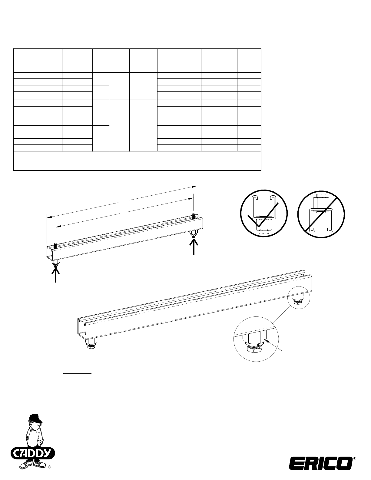
Note: Product must be installed with the open side of the channel facing up.
See Figure 1.
L1
L
FIGURE 1
1/2 F
1/2 F
See Sheet 2
for Installation
WARNING:
ERICO products shall be installed and used only as indicated in ERICO product instruction sheets and training materials. Instruction sheets are available at 1.
www.erico.com and from your ERICO customer service representative.
ERICO products must never be used for a purpose other than the purpose for which they were designed or in a manner that exceeds specified load ratings.2.
All instructions must be completely followed to ensure proper and safe installation and performance. 3.
Improper installation, misuse, misapplication or other failure to completely follow ERICO's instructions and warnings may cause product malfunction, property 4.
damage, serious bodily injury and death.
Products that are manufactured using spring steel components shall be used only in a non-corrosive indoor environment. 5.
All pipe supports, hangers, intermediate components and structural attachments must ONLY be used as described herein and are NEVER to be used for any 6.
other purpose.
NOTE: All load ratings are for static conditions and do not account for dynamic loading such as wind, water or seismic loads, unless otherwise noted.
The customer is responsible for:
a. Conformance to all governing codes.
b. The integrity of structures to which the products are attached, including their capability of safely accepting the loads imposed, as evaluated by a qualified
engineer.
c. Using appropriate industry standard hardware as noted above.
SAFETY INSTRUCTIONS:
All governing codes and regulations and those required by the job site must be observed.
Always use appropriate safety equipment such as eye protection, hard hat, and gloves as appropriate to the application.
CADDY, CADWELD, CRITEC, ERICO, ERIFLEX, ERITECH, and LENTON are registered trademarks of ERICO International Corporation.
TECHNICA L SUPPORT:
www.erico.com
CFS508_B
1 OF 2
© 2014 ERICO International Corporation.
Page 2
INSTRUCTION SHEET
CADDY® ROD LOCK Strut
M8 & M10, A25 & C15 Metric Struts, 550 mm - 1050 mm Span
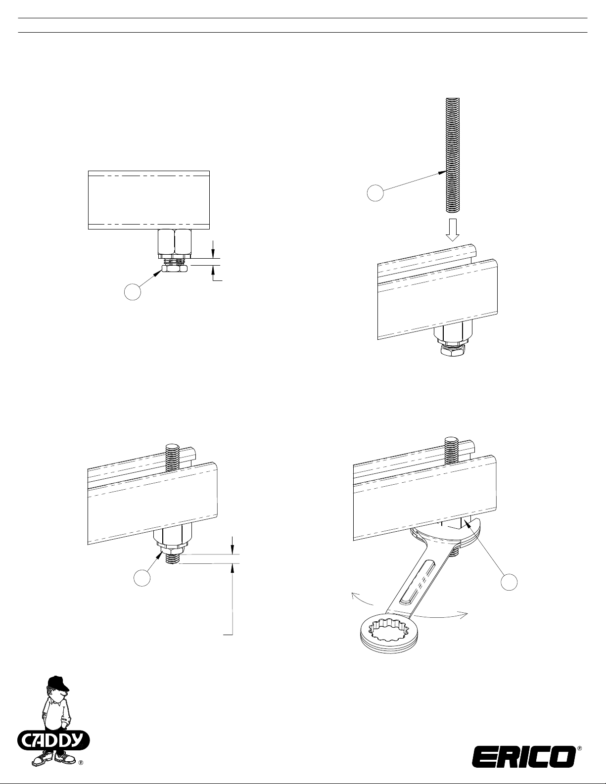
2
Push threaded rod into
CADDY ROD LOCK device
Maximum Open Position
1
Rotate locknut counter clockwise
until reaches stopping position
3
Hand tighten
bottom locknut
The end of the threaded rod
must be positioned at or
below bottom of locknut
CADDY, CADWELD, CRITEC, ERICO, ERIFLEX, ERITECH, and LENTON are registered trademarks of ERICO International Corporation.
TECHNICA L SUPPORT:
www.erico.com
CFS508_B
2 OF 2
© 2014 ERICO International Corporation.
Rotate hex shaped
main housing with
24mm or 15/16"
open end wrench
to adjust height of
threaded rod.
4
 Loading...