

Page 1
INSTRUCTION SHEET
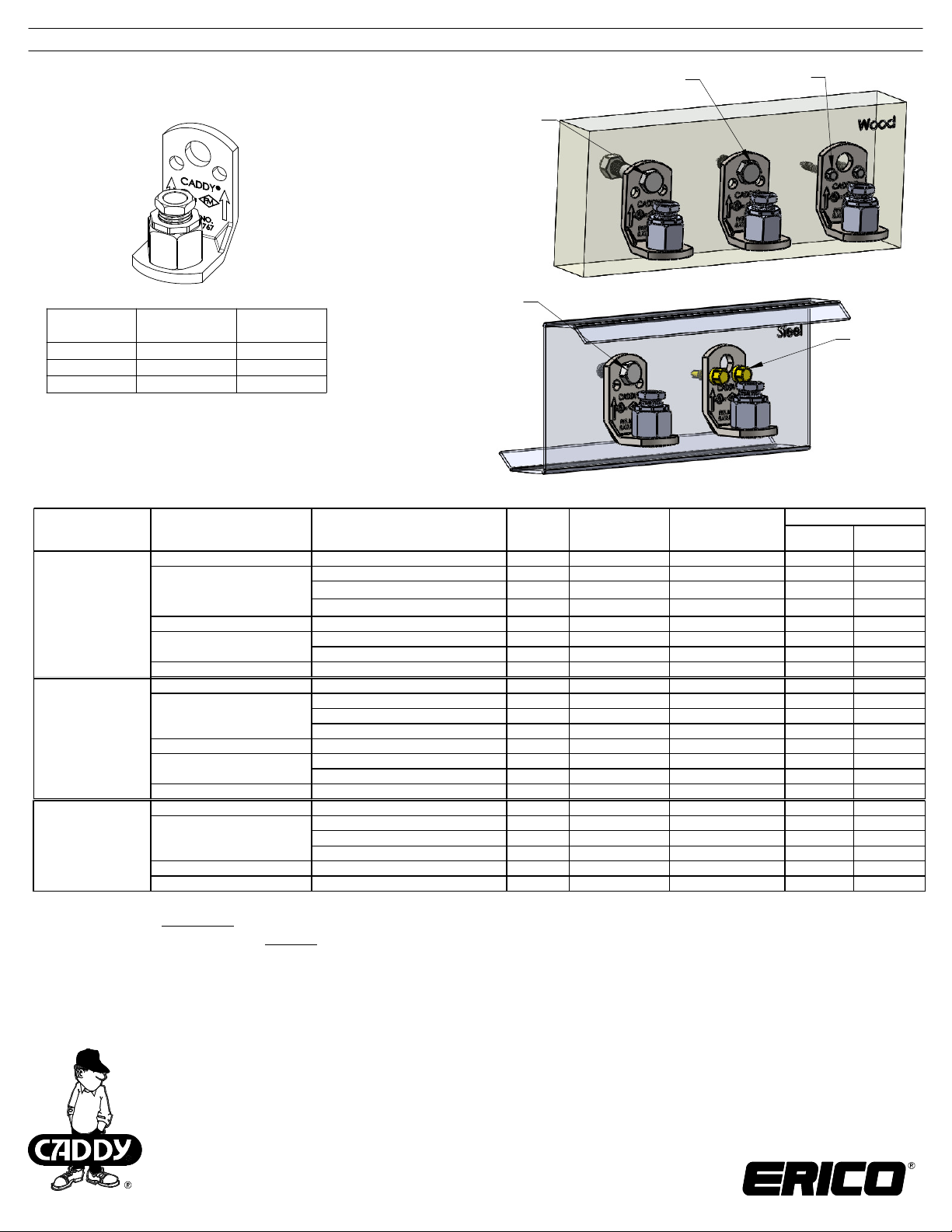
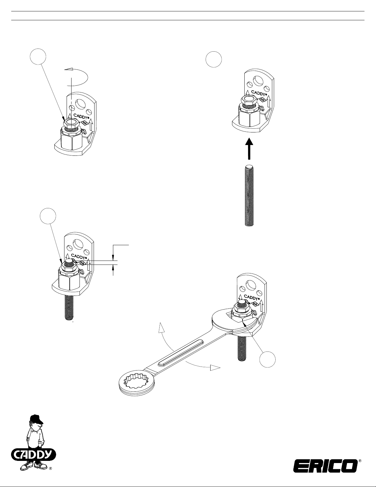
CADDY ROD LOCK L-Bracket
Part
Number
CRLL37EG N/A 3/8"
CRLLM10EG* 390012 M10
CRLLM8EG* 390011 M8
®
Article
Number
Rod Size
(1) bolt, washer & nut
(washer under nut
on opposite side)
(1) bolt, washer & nut
(washer under nut
on opposite side)
*VdS Approval G413038. Complies with VdS®
CEA 4001 (Guidelines for Sprinkler Systems)
Chapter 15.2.3 and shall be installed in
accordance with VdS CEA 4001.
(1) lag screw
(2) 1/4" or M6
lag screws
(2) 1/4" or M6
self drill screw
or tap screw
Part Number
(Article Numbe r)
CRLL37EG
CRLLM10EG
(390012)
CRLLM8EG
(390011)
Structure Fastener Type
Concrete 1/2" 1 4" or DN100 4" or DN100 700 3114
Wood
Min. 16 Ga. [1.5mm] Steel 1/2" bolt, nut, washer 1 4" or DN100 4" or DN100 700 3114
Min. 14 Ga. [2mm] Steel
Min. 12 Ga. [3mm] Steel 1/4" x 1" s elf drill or tap screw 2 4" or DN100 4" or DN100 700 3114
Concrete M10 1 4" or DN100 4" or DN100 700 3114
Wood
Min. 16 Ga. [1.5mm] Steel M10 bolt, nut, washer 1 4" or DN100 4" or DN100 700 3114
Min. 14 Ga. [2mm] Steel
Min. 12 Ga. [3mm] Steel M6 x 25mm self drill or tap screw 2 4" or DN100 4" or DN100 700 3114
Concrete M10 1 N/A N/A 500 2224
Wood
Min. 16 Ga. [1.5mm] Steel M10 bolt, nut, washer 1 N/A N/A 500 2224
Min. 14 Ga. [2mm] Steel M6 x 25mm self drill or tap screw 2 N/A N/A 500 2224
WARNING:
ERICO products shall be installed and used only as indicated in ERICO product instruction sheets and training materials. Instruction sheets are available at 1.
www.erico.com and from your ERICO customer service representative.
ERICO products must never be used for a purpose other than the purpose for which they were designed or in a manner that exceeds specified load ratings.2.
All instructions must be completely followed to ensure proper and safe installation and performance. 3.
Improper installation, misuse, misapplication or other failure to completely follow ERICO's instructions and warnings may cause product malfunction, property 4.
damage, serious bodily injury and death.
Products that are manufactured using spring steel components shall be used only in a non-corrosive indoor environment. 5.
All pipe supports, hangers, intermediate components and structural attachments must ONLY be used as described herein and are NEVER to be used for any
6.
other purpose.
NOTE: All load ratings are for static conditions and do not account for dynamic loading such as wind, water or seismic loads, unless otherwise noted.
The customer is responsible for:
a. Conformance to all governing codes.
b. The integrity of structures to which the products are attached, including their capability of safely accepting the loads imposed, as evaluated by a qualified engineer.
c. Using appropriate industry standard hardware as noted above.
SAFETY INSTRUCTIONS:
All governing codes and regulations and those required by the job site must be observed.
Always use appropriate safety equipment such as eye protection, hard hat, and gloves as appropriate to the application.
FM is a registered certification mark of FM Approvals LLC, LTD.
UL is a registered trademark of UL LLC
VdS is a registered trademark of VdS Schadenverhütung GmbH
CADDY, CADWELD, CRITEC, ERICO , ERIFLEX, ERITECH, a nd LENTON are registered trademarks of ERICO International Corporation.
1/2" x 3" lag s crew 1 4" or DN100 4" or DN100 600 2669
1/2" bolt, nut, washer 1 4" or DN100 4" or DN100 700 3114
1/4" x 1-1/2" lag screw 2 N/A N/A 300 1334
1/2" bolt, nut, washer 1 4" or DN100 4" or DN100 700 3114
1/4" x 1" s elf drill or tap screw 2 4" or DN100 3-1/2" or DN90 700 3114
M10 x 80mm lag screw 1 2" or DN50 2" or DN50 600 2669
M10 bolt, nut, washer 1 4" or DN100 4" or DN100 700 3114
M6 x 40mm lag screw 2 N/A N/A 300 1334
M10 bolt, nut, washer 1 4" or DN100 4" or DN100 700 3114
M6 x 25mm self drill or tap screw 2 4" or DN100 3-1/2" or DN90 700 3114
M10 x 80mm lag screw 1 N/A N/A 500 2224
M10 bolt, nut, washer 1 N/A N/A 500 2224
M6 x 40mm lag screw 2 N/A N/A 300 1334
Fastener
Quantity
Max . UL®203
pipe size (NPS)
Max . FM®1951
pipe size (NPS)
UL2239/ MSS/ Gene ral
lbs N
TECHNICAL SUPPORT:
www.erico.com
CFS457_F
1 OF 2
© 2012, 2013, 2014 ERICO International Corporation
Page 2
INSTRUCTION SHEET
CADDY® ROD LOCK L-Bracket
Rotate lock nut counter clockwise
1
until reaches the fully extended position
Tighten lock nut
3
Push rod into
2
CADDY ROD LOCK L-Bracket
Top of rod must be
positioned at or above
top of lock nut
4
Rotate the hex housing to finely tune
the height of the supported assembly:
Clockwise = adjust assembly down
Counter-clockwise = adjust assembly up
CADDY, CADWELD, CRITEC, ERICO , ERIFLEX, ERITECH, a nd LENTON are registered trademarks of ERICO International Corporation.
TECHNICAL SUPPORT:
www.erico.com
CFS457_F
2 OF 2
© 2012, 2013, 2014 ERICO International Corporation
 Loading...