

Page 1
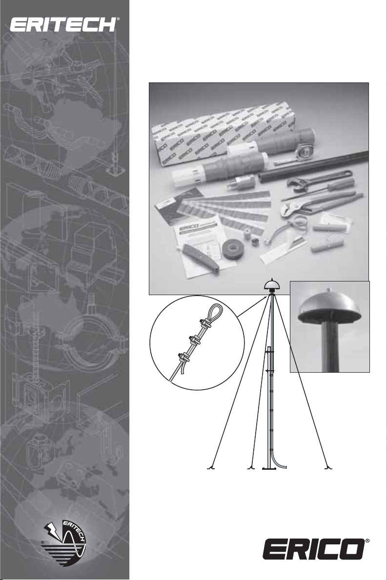
ERITECH® SYSTEM 3000
Installation, Operation and
Maintenance Manual
Page 2

ERITECH® SYSTEM 3000 Installation,
Operation and Maintenance Manual
EDITION 14
Copyright © 2009, 2012 ERICO International Corporation. All rights reserved.
CADDY, CADWELD, CRITEC, ERICO, ERITECH, ERIFLEX and LENTON are registered
First printed 1988
trademarks of ERICO International Corporation.
IP79131_B
REVISION 2
Page 3

INSTALLATION, OPERATION AND MAINTENANCE MANUAL
The ERITECH® SYSTEM 3000
Installation, Operation
and Maintenance Manual
IP79131_B
www.erico.com
1
Page 4

INSTALLATION, OPERATION AND MAINTENANCE MANUAL
Table of Contents
Pre-Installation Requirements ................................................................................ Page 4
Grounding Systems ................................................................................................. Page 5
Downconductors ..................................................................................................... Page 5
Structural Bonding Braid & Conductive Structural Points ...................................... Page 6
Lightning Event Counters ....................................................................................... Page 6
ERITECH
Masts ........................................................................................................................ Page 7
Checking Lightning Protection Components on Receipt ................................. Page 8
ERITECH
Grounding Systems Installation ............................................................................. Page 9
Ground Resistance Lowering Compounds ......................................................... Page 12
Insulation of Grounding Systems Page ............................................................... Page 12
Bonding the Lightning Protection Ground to other Service Grounds .................. Page 12
Labelling ............................................................................................................ Page 13
Downconductors .................................................................................................. Page 14
Downconductor Hauling .................................................................................... Page 14
Penetrations ....................................................................................................... Page 16
Routing ............................................................................................................. Page 16
Securing the Downconductor ............................................................................ Page 18
Use of Mast or Conventional Cable as the Downconductor ............................... Page 19
Labelling ............................................................................................................ Page 20
Structure Bonding Braid .................................................................................... Page 20
Terminating the ERITECH
Terminating the ERITECH
Terminals and Masts ............................................................................................. Page 40
Terminals ........................................................................................................... Page 40
Masts ................................................................................................................ Page 40
Mast Bases .........................................................................................................Page 41
Mast Couplings & Guying Points ....................................................................... Page 42
Guying .............................................................................................................. Page 44
Raising of Mast .................................................................................................. Page 45
Lightning Event Counter ................................................................................ Page 48
Long Lengths of ERITECH ERICORE Downconductor ........................................ Page 49
Parallel ERITECH
Series connected ERITECH ERICORE cable sections ............................................. Page 52
Practical Examples for long lengths of ERITECH ERICORE ............................. Page 54
Certification .............................................................................................................. Page 55
Operation & Maintenance ..................................................................................... Page 55
Maintenance Records ........................................................................................... Page 58
Specifications ............................................................................................................ Page 59
Glossary ....................................................................................................................... Page 62
Certificate of Compliance and Warranty Registration .................... Inside Back Cover
®
DYNASPHERE Terminals ......................................................................... Page 6
®
SYSTEM 3000 Installation ...................................................................... Page 9
®
ERICORE Lower End ................................................. Page 24
ERICORE Upper End .................................................. Page 28
®
ERICORE cables ......................................................................... Page 51
2
www.erico.com
Page 5
INSTALLATION, OPERATION AND MAINTENANCE MANUAL
ERITECH® SYSTEM 3000
THE ERITECH® SYSTEM 3000
Installation, Operation
and Maintenance Manual
Due to ongoing research into the phenomena of lightning and lightning
protection technology and product improvement, ERICO reserves the right to
alter any information and specifications contained herein at any time without
notice. Users should check with ERICO to ensure they have the latest edition.
Warning:
1. ERICO products shall be installed and used only as indicated in ERCIO product instruction
sheets and training materials. Instruction sheets are available at www.erico.com and from
your ERICO customer service representative.
2. ERICO products must never be used for a purpose other than the purpose for which they
were designed or in a manner that exceeds specified load ratings.
3. All instructions must be completely followed to ensure proper and safe installation and
performance.
4. Improper installation, misuse, misapplication or other failure to completely follow ERICO’s
instructions and warnings may cause product malfunction, property damage, serious bodily
injury and death.
SAFETY INSTRUCTIONS: All governing codes and regulations and those required by the job site
must be observed. Always use appropriate safety equipment such as eye protection, hard hat,
and gloves as appropriate to the application.
®
The ERITECH
International patents on the ERITECH SYSTEM 3000 are existing.
Local Distributors should be the user’s first point of contact with supply, delivery, installation,
limited warranty, and checking of the system for compliance with Manufacturer’s instructions.
www.erico.com
SYSTEM 3000 is manufactured by ERICO.
3
Page 6
INSTALLATION, OPERATION AND MAINTENANCE MANUAL
Pre-Installation Requirements
This manual is a guide to the Installation,
Operation and Maintenance of the ERITECH
SYSTEM 3000 Lightning Protection System.
It assumes that the system to be installed
has been designed by an authorized ERICO
representative. The system design will
include:
t
Grounding system design - a
configuration should be designed as
a result of soil resistivity analysis.
®
t Downconductor routes - chosen to
avoid other services, maintain
minimum bending radii and minimize
downconductor run length.
t Downconductor securing requirements.
t Terminal types - operating environment.
t CAD analysis design software which
determines terminal placement, mast &
height requirements as well as protection
level calculation.
All of the above are recommended for a
successful installation. If there is any doubt
about any of the points mentioned, please
contact ERICO or your nearest Distributor
for clarification.
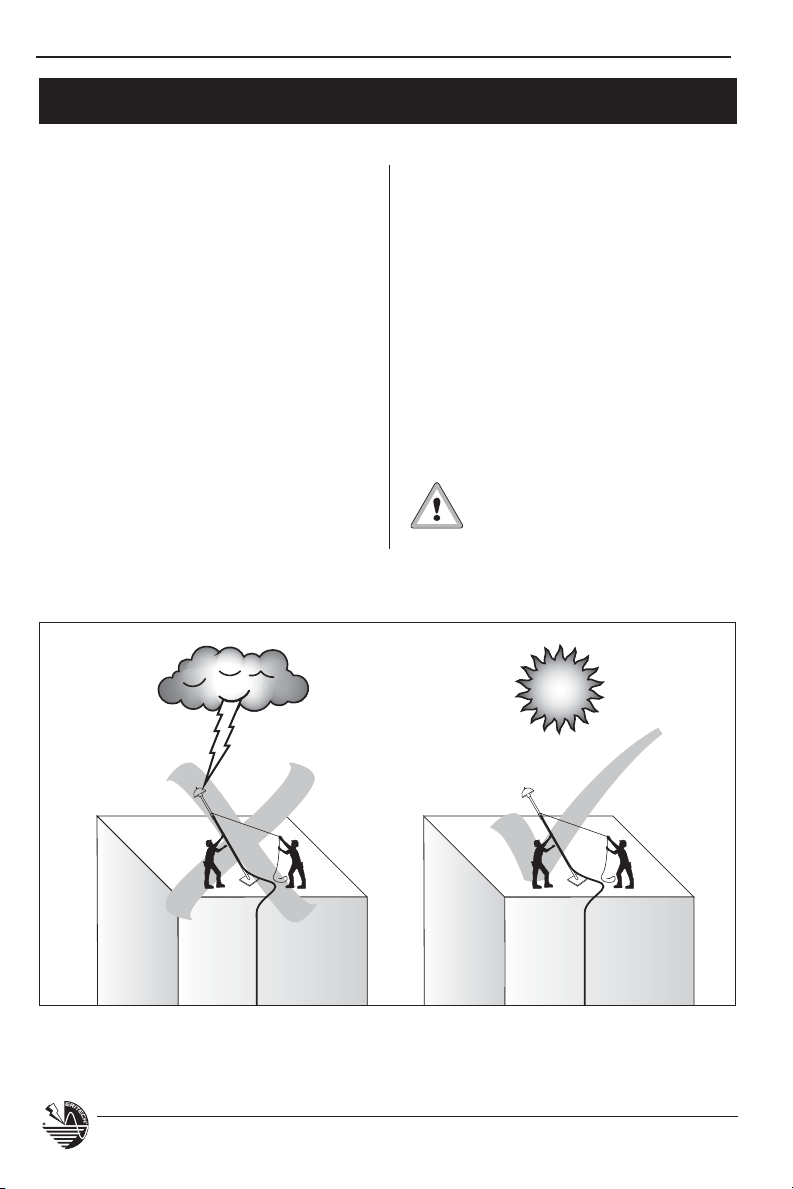
Only attempt to install the
ERITECH SYSTEM 3000
during storm-free periods.
Figure 1.
4
www.erico.com
Page 7
INSTALLATION, OPERATION AND MAINTENANCE MANUAL
The recommended order of installation is as follows:
1. Full installation of the grounding system.
2. Full installation of the downconductor.
3. Termination of the downconductor to the grounding system.
4. Upper termination of the downconductor (may already have been completed
by ERICO) and connection to the ERITECH
5. Termination of bonding cable from upper termination to structure
(if required).
6. Raise mast into position and secure.
®
DYNASPHERE air terminal.
Grounding Systems
The grounding system is critical to the
integrity of any lightning protection
installation and should include
consideration of:
t Local Standards compliance
(IEC 61024-1, BS 6551, AS1768-1991,
®
780, C22.1-98, NEC® etc.)
NFPA
t Available space / location.
t Natural soil conditions - resistivity of
soil, soil moisture content, soil
temperature range, etc.
t Location of underground services -
Power, Communications, Fuel, Gas,
Water, etc.
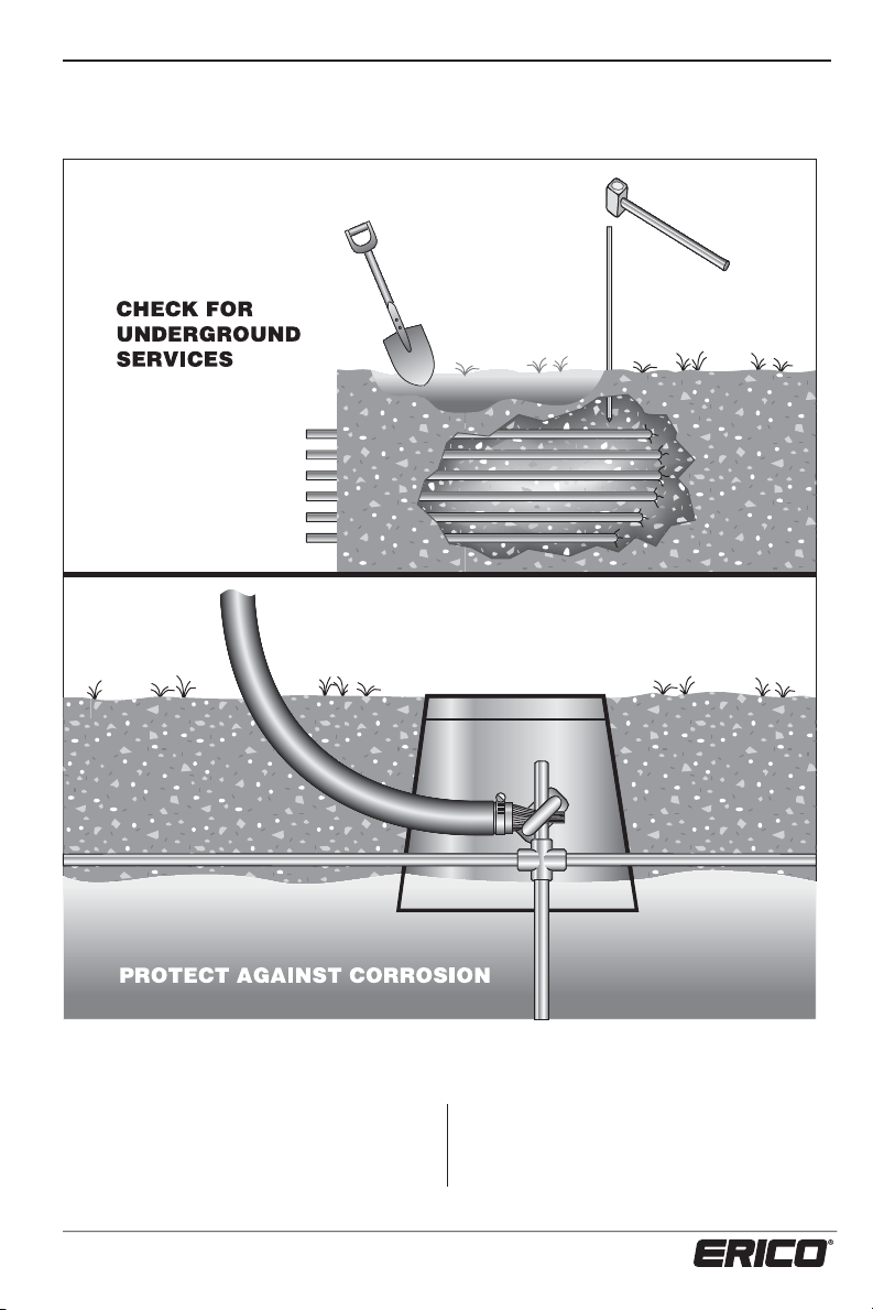
t Corrosive environments, ie: salt
water, acid / alkaline contaminated
ground mass.
t Use of suitable grounding rods such
as ERITECH
®
rods.
t Minimization of risk to personnel.
Contact an ERICO office or Distributor if you
require further advice on grounding systems.
Downconductors
The ERITECH® ERICORE downconductor
or other recommended downconductor
should have been selected during the design
stage, as should the route, length and any
preterminations of the downconductor.
Re-check intended route of
downconductor immediately
prior to installation to ensure
that:
t There are no structural changes or
additions that may effect the initial
design.
t Most direct route possible to the
grounding system with minimal
number of bends and as flush with
the structure as possible.
t Minimum bending radii maintained
(500 mm, 20 in.).
t Parallel routing with other services -
minimum separation = 2 m (80 in.).
t Attachment to the structure is at a
maximum of every 1 m (40 in.) for the top
10% of the downconductor route and
2 m (80 in.) from then on.
t Pipe installations follow the instructions
given on page 17.
www.erico.com
5
Page 8
INSTALLATION, OPERATION AND MAINTENANCE MANUAL
Re-check:
t Securing of downconductor - saddles,
cable ties, beam clamps, cable hangers,
etc, are appropriate.
t Method of cable installation, ie. cable
upper terminated on the outside of the
drum - to be rolled off from the base of
the structure, or cable upper terminated
on the inside of the drum - to be rolled
off from the top of the structure,
(refer Figure 6 on page 15).
t The outer sheath of the downconductor
must be electrically bonded to a
conductive structural point within 5 m
(17 ft) of the upper termination kit.
Structural Bonding Braid & Conductive
Structural Points
When installing the upper end of
the downconductor on a masonry
structure (concrete panels, brick,
etc), the downconductor should be secured
directly to the structural steel work. In
addition, the bonding cable (supplied in the
termination kit) must be connected via
2
(8 AWG) insulated copper cable to
6 mm
the nearest conductive structural point. This
point should be where the downconductor
first comes into contact with the structure
and may be either structural steel work or
the reinforcing within concrete panels or
slabs.
See Pages 18 to 24, figures 10-17 for more
details and diagrams.
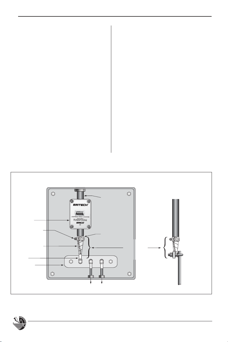
Lightning Event Counters
The Lightning Event Counter (LEC IV) is
a device for registering and recording
the number of strikes that the ERITECH
SYSTEM 3000 has intercepted. The design
of this counter allows many installation
alternatives on the downconductor
as discussed in later text. Also, see
Specifications on page 60.
The following should be considered prior to
installation of the Lightning Event Counter:
®
t It is advisable to locate the LEC IV in
a secure area that is not prone to
contact with moving objects, theft,
or vandalism.
t If the LEC IV is to be encased in an
additional enclosure, ensure that it is
mounted to enable easy access to the
display, (see figure 32 on page 48).
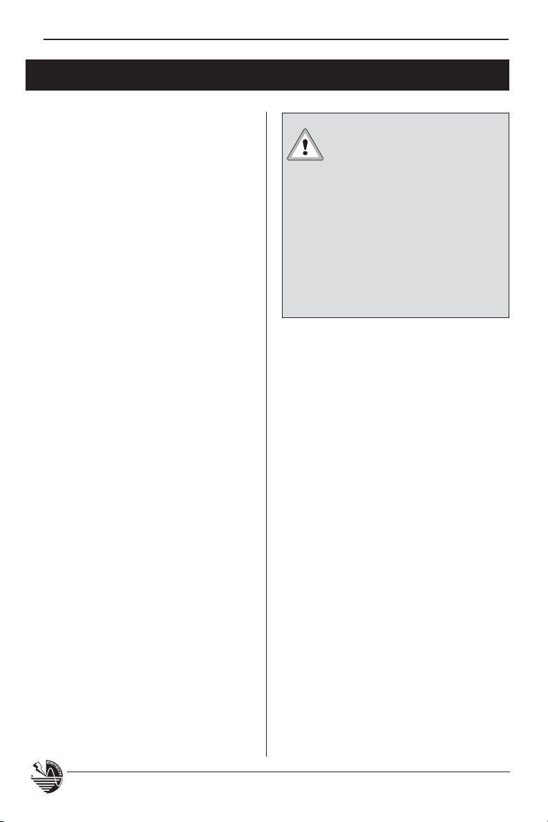
ERITECH® DYNASPHERE
Terminals
The ERITECH® DYNASPHERE is the air
terminal of the ERITECH SYSTEM 3000.
Ensure that the appropriate air terminal has
been provided.
It is recommended that this point be
determined prior to the installation to allow
for any site work or equipment that may be
required prior to the installation.
2
The 6 mm
and the length of the cable will need
to be determined and obtained before
commencing the installation.
(8 AWG) cable is not supplied
Suitable for use in:
t General purpose applications
t High temperature environments
t Corrosive environments (salt or acid
atmosphere)
6
www.erico.com
Page 9
INSTALLATION, OPERATION AND MAINTENANCE MANUAL
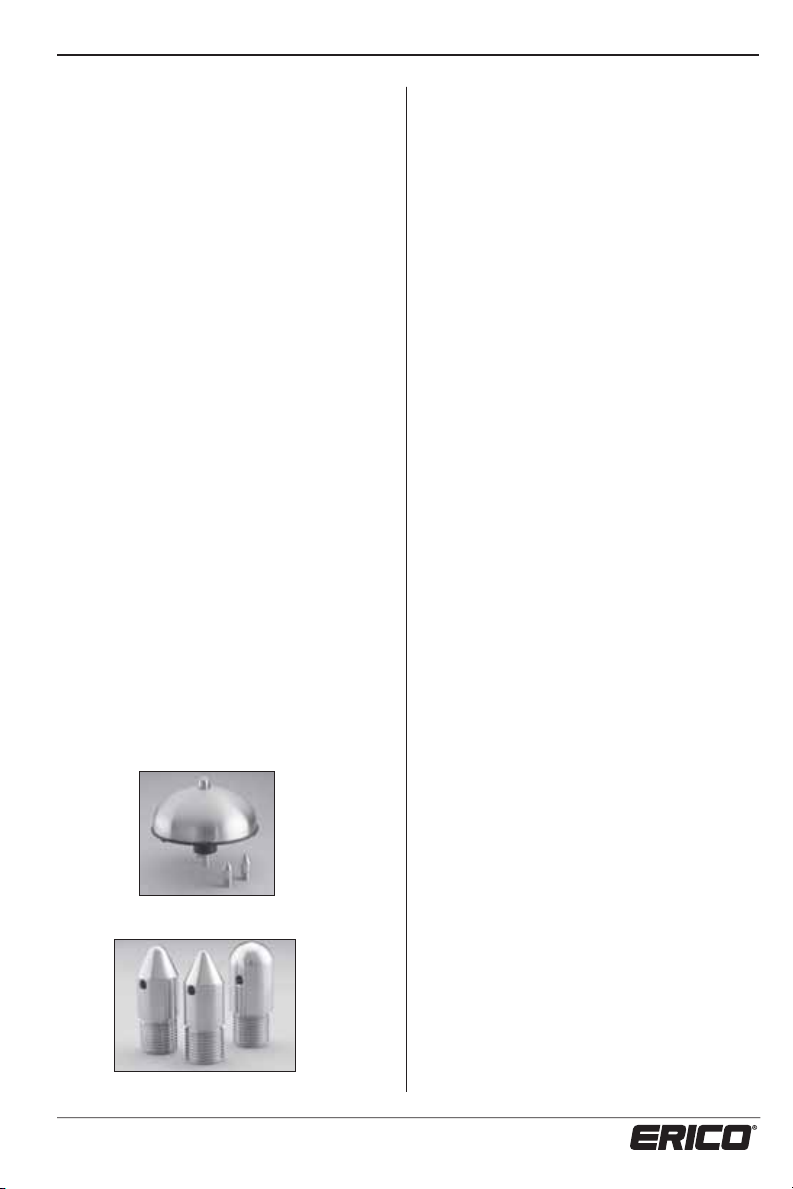
Ensure the air terminal is supplied with the
finial tip secured in place. The air terminal
is supplied with three different finial tip
configurations (two separate, and one
secured in place), similar to that shown
in photo 1. It is important that the
correct finial tip is installed, specific
to the application. Photo 2 shows the
three different finial tip
sharp to blunt in dimension.
(middle), medium tip (left) and rounded tip
(right). The application of each of these tips
is detailed below:
sizes, ranging from
The sharp tip
Masts
There are three main types of mast
configurations:
t Guyed - generally required for mast
t Sharp Tip – Terminal heights less than
20 m (65 ft)
t Medium Tip – Terminal heights less
50 m (165 ft), greater than 20 m
than
(65 ft)
t Cantilevered - the lower third of the
t Rounded Tip – Terminal heights greater
than 50 m (165 ft)
Note: heights listed refer to the actual terminal height above ground
level
If required, replace the finial tip supplied
with the appropriate tip for the application,
and tighten firmly.
Warning – Do not install the ERITECH®
DYNASPHERE
correct finial tip.
without installing the
t Free-standing - base support only.
Ensure that the configurations and
heights for your specific installation
conform to the design and consultation
directives.
Specific advice for each mast configuration is provided on pages 40 to 47.
When all of the components for the
ERITECH
received, they should be checked against
the design “Bill of Materials” and for any
possible shipping loss or damage.
heights of over 3 m (10 ft) or for
climatic conditions where wind gusts
may exceed 160 km/h (100 mph).
Always consult with a local civil
engineer if in doubt. The mast is
anchored at the base and then guyed
using one or two guy sets, depending
on the mast height and configuration,
each with 3 lengths of non conductive
guying material.
mast is secured to a vertical surface
to provide support. These may also
require guying depending on mast
height.
®
SYSTEM 3000 have been
1 – ERITECH DYNASPHERE with two spare finial tips.
2 – Three (3) ERITECH DYNASPHERE finial tip sizes.
www.erico.com
7
Page 10

INSTALLATION, OPERATION AND MAINTENANCE MANUAL
Checking Lightning Protection Components
on Receipt
Before installation, in particular, check the
following:
Terminal(s)
t ERITECH
not been dented in any way.
®
DYNASPHERE terminals have
t The correct finial tip has been installed,
based on the overall height of the air
terminal above ground.
®
ERITECH
ERICORE Downconductor(s)
t The cable drum (if supplied) is in a
serviceable condition.
t Correct length(s)
t That there is no obvious damage to the
cable.
t Is terminated as required. If the
downconductor has been preterminated before shipment, check that
the termination is still intact and in
good order. See note on Page 14 on
removing protective covers.
t If the Upper Termination Kit has been
supplied separately, check that the
Cold-Shrink tube in the kit is in good
order, has no tears or cuts and has
not collapsed.
This information along with downconductor lengths and quantities (if
more than one length on the one
drum), will be printed on a label on the
side of the Cable Drum(s).
8
www.erico.com
Page 11
INSTALLATION, OPERATION AND MAINTENANCE MANUAL
ERITECH® SYSTEM 3000 Installation
During the installation of the ERITECH® SYSTEM 3000, all site restrictions
and safety requirements must be followed.
It is important to follow the recommended order of installation:
1. Full installation of the grounding system.
2. Full installation of the downconductor.
3. Termination of the downconductor to the grounding system.
4. Upper termination of the downconductor (may already have been completed
by ERICO®) and connection to the ERITECH® DYNASPHERE air terminal with
correctly sized finial tip.
5. Termination of bonding cable from upper termination to structure.
6. Raise mast into position and secure.
Only attempt to install the
ERITECH SYSTEM 3000
storm-free periods.
If the terminal must be raised before
being connected to the ground system, or
cannot be immediately connected, then
attempt to connect the lower end of the
down-conductor to either the structure
steel reinforcing or some other reasonable
ground point.
during
Grounding Systems
Installation
Prior to the installation of the
lightning protection grounding
systems, it is important to refer
to site drawings of all underground
www.erico.com
services to ensure that these are
avoided and not interrupted during
trenching, excavation, boring or
driving ground rods, (see figure 4 on
page 11).
Care must be taken to follow the
ground survey design. Ensure the
correct materials have been provided
and are used to achieve an acceptable
Ground DC resistance (typically <10Ω).
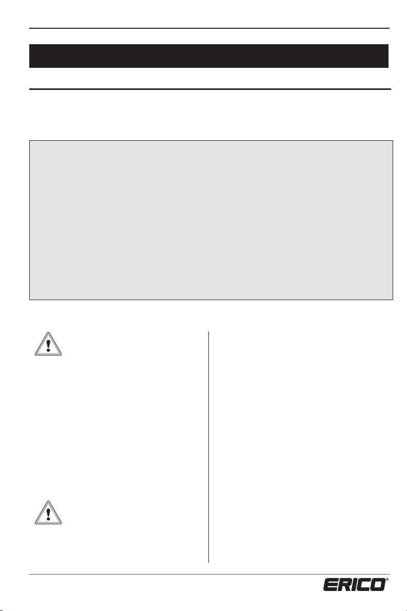
Examples of typical grounding systems
that may be used (Note: these may or may
not be relevant to the specific ERITECH
SYSTEM 3000 design) are shown in figures
2 and 3 on page 10.
9
Page 12
INSTALLATION, OPERATION AND MAINTENANCE MANUAL
Lightning Event
Counter - LEC IV
Ground rods
clamped or
welded to
copper ground
tape using
CADWELD
Each trench is treated
with GEM or ERITECH
Enhancing Compounds
®
Conductive Saddles
ERITECH
®
ERICORE
Ground Pit
Lower Termination
(Bound in Waterproofing
Mastic)
Copper Ground Tape
Typical lengths, minimum of 5 m (17 ft). (Lengths are dependant
upon soil resistivity reading) @ 600 mm (24 in.) depth or greater if
required, to ensure that it is below the frost line.
Figure 2: Radial Ground.
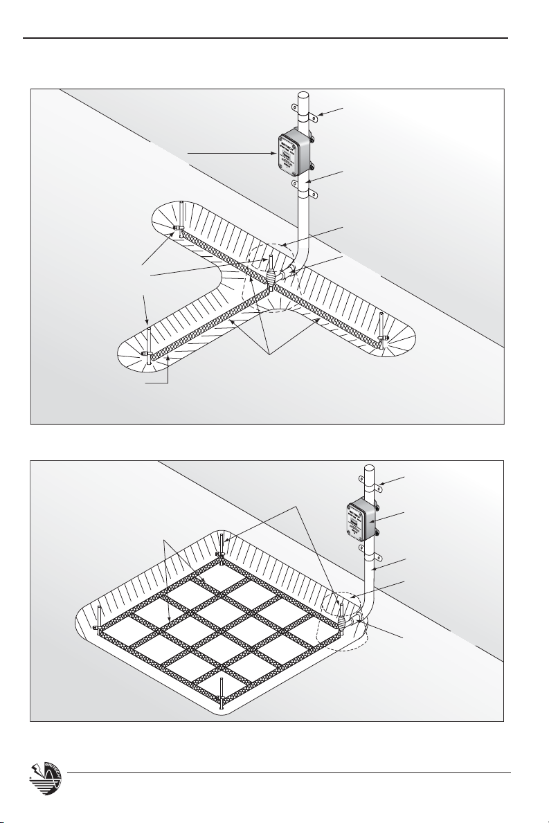
Copper ground tape grid
5000 x 5000 mm (17 x 17 ft.)
@ 600 mm (24 in.) depth or
greater if required to ensure
that it is below the frost line.
Figure 3: Grid Ground.
ERITECH ground rods
clamped or welded to
copper ground tape,
using CADWELD.
10
Conductive
Saddles
Lightning Event
Counter - LEC IV
ERITECH ERICORE
Ground Pit
Lower Termination
(Bound in
Waterproofing
Tape)
www.erico.com
Page 13
INSTALLATION, OPERATION AND MAINTENANCE MANUAL
POWER
GAS
WATER
IRRIGATION
COMMUNICATIONS
SEWERAGE/STORMWATER
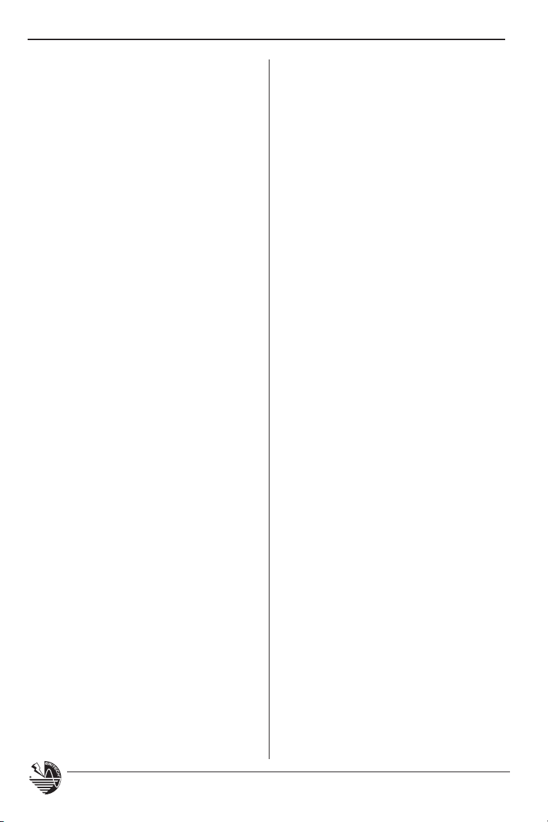
Figure 4: Precautions required for ground pit excavation and lower termination corrosion protection.
It is advised that a ground pit is installed
where the end of the downconductor
This provides a convenient access point for
disconnection and future testing.
terminates to the ground system.
www.erico.com
11
Page 14
INSTALLATION, OPERATION AND MAINTENANCE MANUAL
When using ground rods it is advisable to:
t Use driving heads to prevent
mushrooming on top of the rod.
t Use driving heads when using
coupled rods.
tUse a post or picket driver.
When bonding the grounding system
components, try to use the recommended
methods suggested below:
t CADWELD
used to provide permanent electrical
bonding, corrosion resistance and
mechanical strength between
conductors, including most types
of copper cable, bar, rod, tape,
structural steel work, reinforcing
steel and pipe.
t Supplied ground rod clamps should
be used for termination of ERITECH
ERICORE downconductors directly
to ground rods. This allows later
disconnection for maintenance
requirements.
®
connections must be
®
t Use of aluminum lugs or couplings is
prohibited.
t Waterproofing mastic tape should be
used for waterproofing corrosion
vulnerable connections.
Ground Resistance Lowering
Compounds
Ground enhancing compounds, (such as
GEM) are recommended and supplied when
the existing soil mass has a high resistivity.
These compounds can be used to increase
the total surface area of grounding
conductors,
resistance / impedance.
Compounds may require water and a
mixing container.
thereby reducing the ground
When applying these compounds, be sure
to take necessary handling precautions
as advised by the product instructions,
and ensure that the directions for use are
followed correctly.
Insulation of Grounding
Systems
In some installations, it may be necessary
to insulate part of the ground system from
an area of the surface, for the purposes of
safety or isolation, (pedestrian walkways,
proximity to other services, etc.). In this
situation, it is recommended that a
minimum of 70 mm
copper cable is run in PVC conduit to the
connection point (start) of the intended
ground system. This conduit should be at
a depth of at least 600 mm (24 in.), or
greater if required, to ensure that it is below
the frost line to the start of the intended
ground system.
Another possible design method for
reducing surface step-potentials may be to
insulate the ground system for the first few
meters of depth from the surface. This is
done by isolating the initial injection point
of the downconductor from the surface
of the ground mass by running it through
PVC conduit to the required depth before
exposing it to the ground mass.
2
(2/0 AWG), insulated
Bonding the Lightning
Protection Ground to Other
Service Grounds
Where separate grounds exist eg: Structure,
Power, Communications and Lightning
Protection, they should be bonded
to form an equipotential ground plane.
This will eliminate the possibility of
loops and potential differences arising
under transient conditions.
together
ground
12
www.erico.com
Page 15
INSTALLATION, OPERATION AND MAINTENANCE MANUAL
Surface Area of Isolation
Downconductor
Lower Termination
Ground Pit
600 mm (24 in.) or greater to ensure
it is below the frost line.
2 m (80 in.)
2
2/0 (AWG)
Insulated
Conduit
70 mm
Insulated Copper
Cable
Start of
Grounding
System
ERITECH
Ground Rod
Figure 5: Various methods of isolating the ground system.
Authorization may be required by the
particular service providers before bonding
of these grounds takes place.
2
Bonding cable must be 70 mm
(2/0 AWG)
minimum depending on local standards. In
some circumstances, it may be necessary
to use a Transient Earth Clamp (ERICO
Part No. TEC100C) which effectively bonds
all grounds to the same potential under
transient conditions, to satisfy service
providers.
For further information, it is advised that
local applicable standards are consulted, ie
IEC 61024-1, BS 6551, AS1768, NFPA
C22.1-98 and NEC
www.erico.com
®
.
®
780,
13
®
Labelling
The labelling of ground pits or grounding
systems to local requirements is the
responsibility of the customer / installer.
Page 16
INSTALLATION, OPERATION AND MAINTENANCE MANUAL
Downconductors
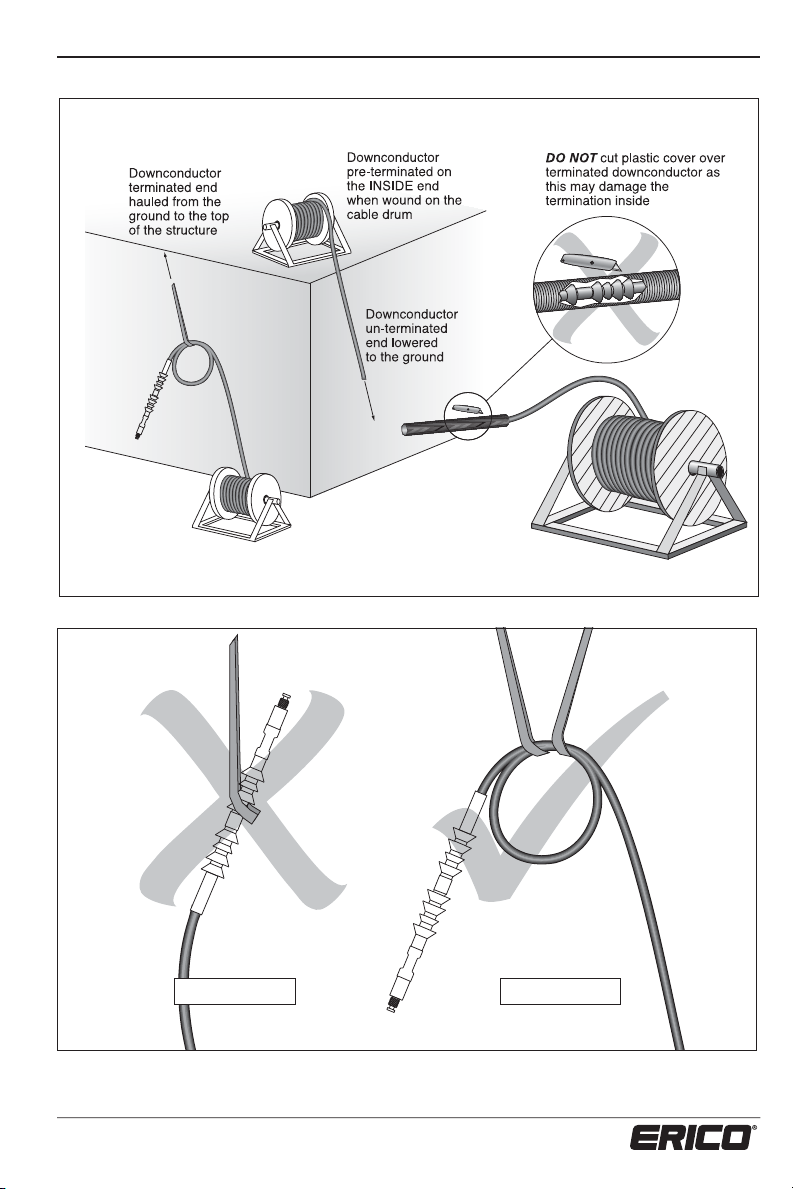
Depending on site requirements, the downconductor(s) may have their
upper terminations completed at a pre-specified end of the cable by
ERICO before shipment. These terminations will be protected by a short
length of flexible PVC tube.
It is VERY IMPORTANT that when removing these tubes, they are not
removed with a knife or cut in any way as this will damage the outer
layer of the termination. It is suggested that the tape and cover are best
removed by hand. (See figure 6)
All ERITECH® purpose-designed downconductors have a semi-conductive outer
sheath which is approximately 2 mm (0.08 in.) thick. Rough or careless handling
of the downconductor can damage this sheath and compromise its performance.
Downconductor Hauling
Locate the downconductor cable drum at
the appropriate location, (refer to figure 6).
When hauling the downconductor, use the
following guide points:
t Ensure that the cable drum, if supplied, is
in a serviceable condition.
t If the downconductor has been upper
terminated on the outside of the drum,
then the downconductor must be hauled
off the drum from the ground.
t If the downconductor has been upper
terminated on the inside of the drum,
then the drum must be at or near the
of the structure, so that the down-
top
conductor
drum towards the base, (see figure 6).
can be unwound from the
t When using slings or ropes to haul
downconductors, use MULTIPLE hitches
around the cable.
t DO NOT sling from the termination
coupling or cold-shrink section of the
terminated downconductor.
t DO NOT use cable stockings over
TERMINATED downconductor ends.
t Protect the downconductor from
abrasion and tearing when hauling over
rough surfaces, at all times, especially
around corners or through penetrations.
14
www.erico.com
Page 17
INSTALLATION, OPERATION AND MAINTENANCE MANUAL
Downconductor pre-terminated
on the OUTSIDE end when
wound on the cable drum
Figure 6: Cable pre-termination and drum locations.
INCORRECT
Figure 7: Incorrect and correct cable hoisting methods.
www.erico.com
CORRECT
15
Page 18
INSTALLATION, OPERATION AND MAINTENANCE MANUAL
Penetrations
Before routing the downconductor through
any penetrations, ensure that:
t If un-terminated, a minimum hole
diameter of 50 mm (2 in.) is provided.
t If terminated, a minimum hole diameter
of 60 mm (2
3
⁄8 in.) is provided.
t Enough physical protection (conduit
or similar) is provided to stop the
downconductor from being damaged
when being fed through the penetration.
t When feeding the upper termination
of the downconductor through any
penetrations, the termination sheds
(flanges) should be temporarily wrapped
in insulation tape to reduce their
diameter and protect them against
abrasion. This is very important as the
cold-shrink tubes are susceptible to
tearing if nicked or scuffed.
If either side of the penetration requires
environmental protection ie: waterproofing,
air-con pressure seal, etc., use a suitable
sealant or deck sealing gland.
Routing
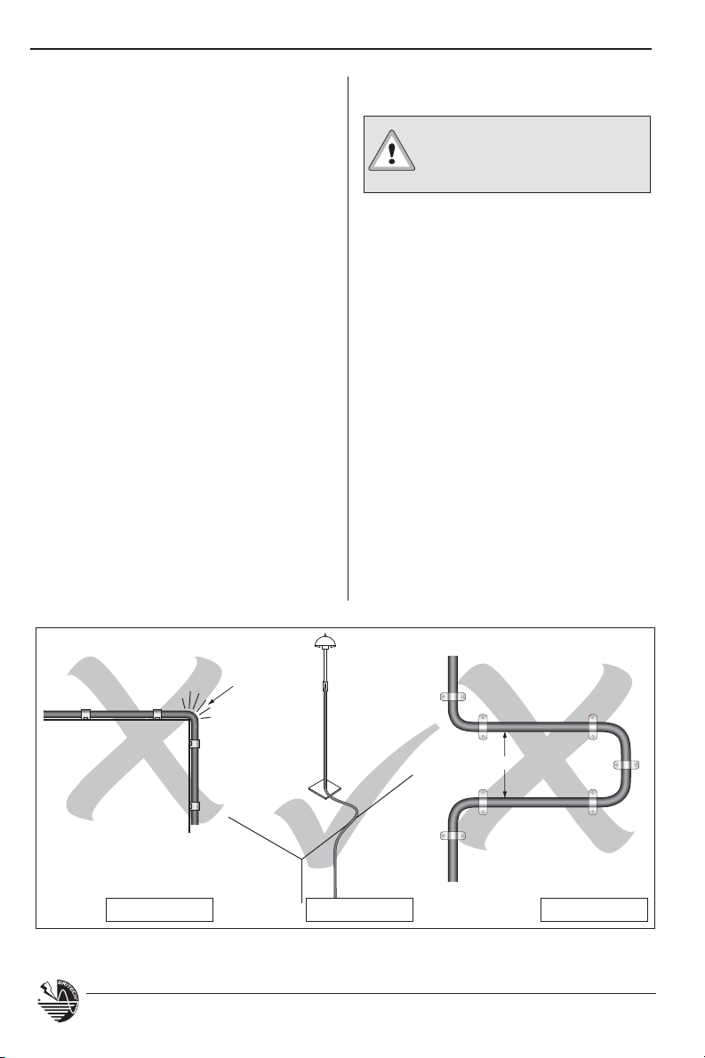
The route taken by the downconductor is very important
and must follow these rules:
t Carefully survey the intended route
of the downconductor immediately
prior to the installation to check for
any alterations that may effect the
original design, ie: structural changes,
new antenna or mast installations, air
conditioning towers or ducting, etc.
t Use the most direct route practical to
minimize the downconductor length.
t To minimize the risk of side-flash,
DO NOT route the downconductor back
beside itself after change of direction,
ie: 180º.
t Minimize number of bends.
t Minimize strain on the downconductor
during installation.
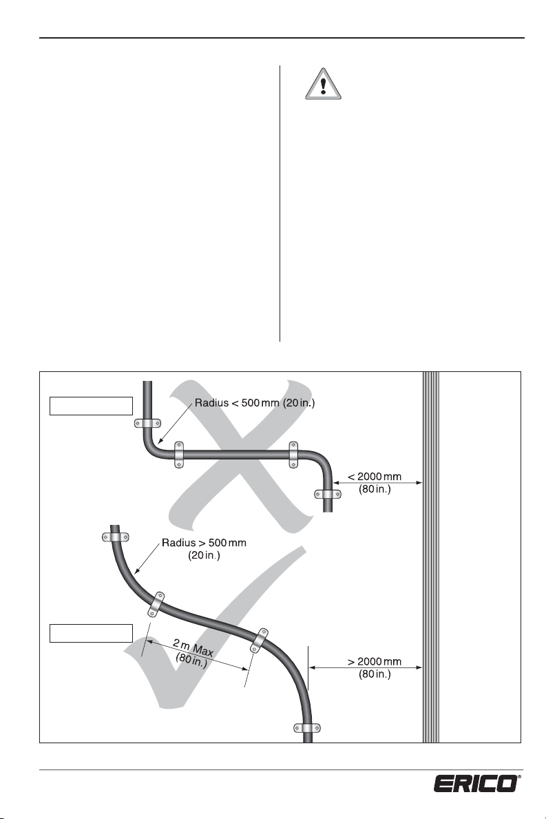
Radius
< 500 mm
(20 in.)
INCORRECT
Figure 8: Correct & incorrect cable routing methods.
CORRECT
16
< 2000 mm (80 in.)
INCORRECT
www.erico.com
Page 19
INSTALLATION, OPERATION AND MAINTENANCE MANUAL
t Ensure bend radius maintained >500 mm
(20 in.).
t Parallel routing with other services -
Minimum separation = 2 m (80 in.). Try
to isolate as much as possible from other
services.
t If the downconductor must cross other
services, ensure that it crosses at right
angles to minimize any inductive effect.
t The lower end of the downconductor
must terminate as close as possible to the
initial injection point of the grounding
system.
INCORRECT
t Allow 500 mm (20 in.) of slack
in the length of downconductor
at the upper end of the cable
to facilitate mast erection and correct
seating of the ERITECH
terminal in the top of the FRP mast.
t
Where isolation of the downconductor
required, (for physical or proximity safety
reasons) install the cable in a
insulating conduit with a min
thickness of 3 mm (
NOTE: This is the only time that the
downconductor should be isolated from the
structure and generally only for 2.4 m
(8 ft.) maximum. DO NOT route the entire
length of downconductor in insulated
conduit.
®
DYNASPHERE
1
imum wall
⁄8 in.).
is
suitable
CORRECT
Figure 9: Correct & incorrect cable routing.
www.erico.com
COMMUNICATIONS / POWER
17
Page 20
INSTALLATION, OPERATION AND MAINTENANCE MANUAL
t To seat the terminal correctly in the top
of the FRP mast, any cable slack will
have to be removed from the mast while
also minimizing any stress on the upper
termination sheds (flanges) by twisting the
FRP mast against the terminal for at least
one turn.
If the downconductor is damaged
during installation, it must be
checked by an ERICO
representative to see if the damage will
effect its safe operation.
Securing the Downconductor
Securing of the downconductor not only provides a
mechanical attachment to the
structure, but also an Electrostatic connection to the structure via
the semiconductive outer sheath of
the downconductor cable.
It is important that the downconductor is both physically and
electrically secured to the entire
length of the structure to relieve both
physical and electrical stresses along
the downconductors’ length.
The electrical bonding of the downconductor is especially important for
at least the first 10% of the downconductor route from the upper
termination, and for this reason the
downconductor must be secured at
least every 1 m (40 in.).
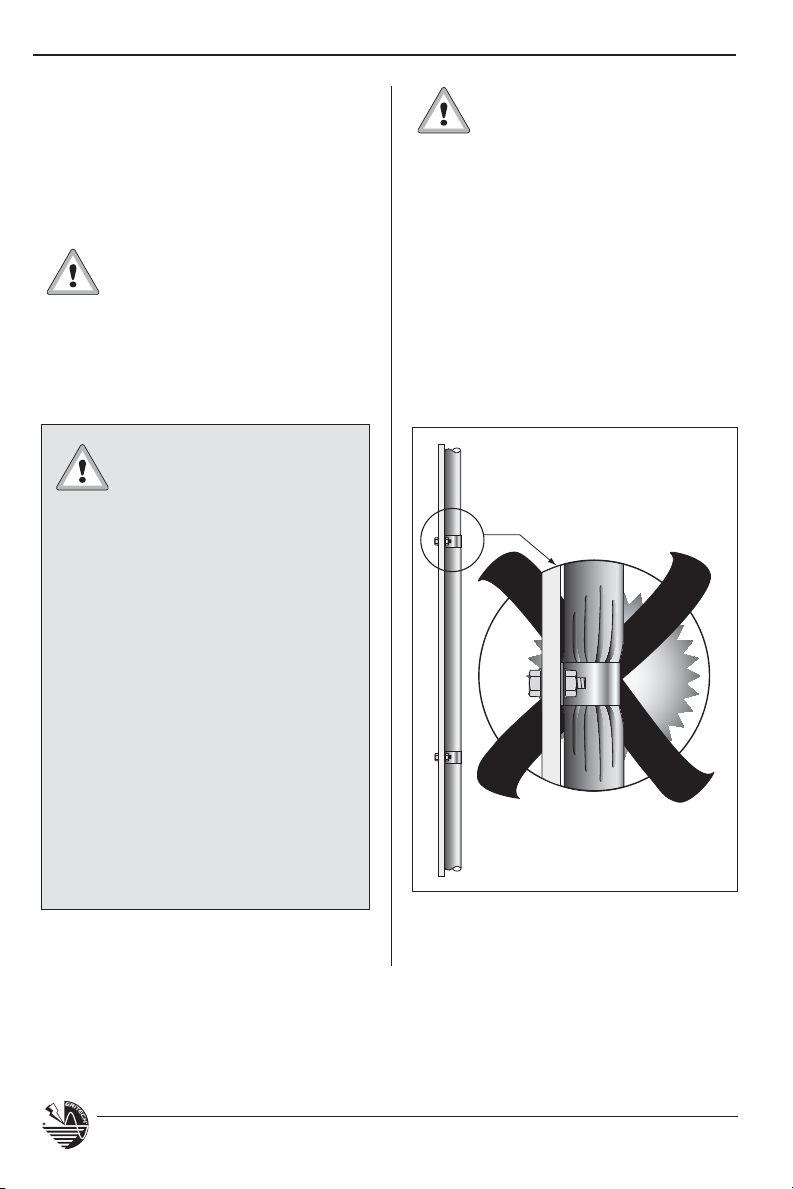
ERITECH® brand of saddles
and conductive clamps are
recommended for the purpose
of securing the downconductor. These
have been specifically designed and
manufactured to mechanically secure and
electrically bond the ERITECH
®
ERICORE
to the structure, while minimizing stress
points on the cable.
Use of a brand of saddles other than
ERITECH can compromise the outer sheath,
creating high stress points which can lead
to flashover, (see figure 10).
Use ERITECH clamps only
Figure 10: Detail shows the need to use ERITECH
Clamps.
18
www.erico.com
Page 21
INSTALLATION, OPERATION AND MAINTENANCE MANUAL
t For brick and concrete walls or roofs,
use the ERITECH
saddles. These have two 6 mm (
®
brand of stainless steel
1
⁄4 in.)
diameter holes on either side and are
suitable for use with masonry anchors.
These saddles can also be used with other
suitable fastenings against wood, fiberglass
and metallic surfaces.
t When securing externally to round section
structures such as pipes, tower legs,
masts, etc, stainless steel cable ties are
recommended. Ensure that these are
firmly secured.
t For securing to other structures such as
angle iron, ie: radio towers, structural
beams etc., use CADDY
clamps and suitable cable clamps from
ERICO.
®
brand of beam
t If the downconductor is to be routed
above a false ceiling, ensure that it is
fixed to the underside of the concrete
floor slab.
t Use of exothermic fastening methods
on ERITECH brand of saddles is NOT
recommended.
t Use of CADDY
strut system) is recommended where
suitable, (see figure 11).
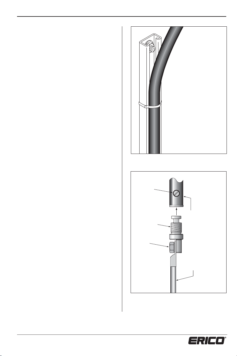
Use of Mast or Conventional
Cable as the Downconducto
In some installations, the mast may be used
as the downconductor or alternatively, in
short-run installations, conventional cable is
sometimes used. In these cases, a Terminal
Lug Coupling Adaptor will be supplied
to allow a lugged 50 mm
2
(2/0 AWG) (depending on local
70 mm
minimum standards) cable termination to
the base of the ERITECH
(see figure 12).
®
ERISTRUT (or other similar
r
2
(1/0 AWG) or
®
DYNASPHERE,
Use of CADDY® ERISTRUT
to anchor downconductor
with S/S cable ties
Figure 11: Downconductor anchored to strut.
Lock Screw
Lightning Protection
Lug Coupling
M10 Bolt
Figure 12: Lug Coupling for non-ERITECH
ERICORE
downconductors.
Terminal Base
2
50 mm
(1/0 AWG)/
2
70 mm
(2/0 AWG)
minimum
downconductor
(or as per local
standards)
®
www.erico.com
19
Page 22
INSTALLATION, OPERATION AND MAINTENANCE MANUAL
Labelling
Vital Warning Labels must be located at
eye level:
t Where there is the possibility of
personnel being in close proximity to
the cable.
t Where the downconductor terminates
to the grounding system.
t At the mast base.
There is a VITAL WARNING LABEL
supplied in the front cover of this manual
and also one supplied in each of the
upper and lower termination kits.
If more labels are required, contact your
nearest ERICO
4.6 m (15 ft.)
FRP Mast
®
Distributor.
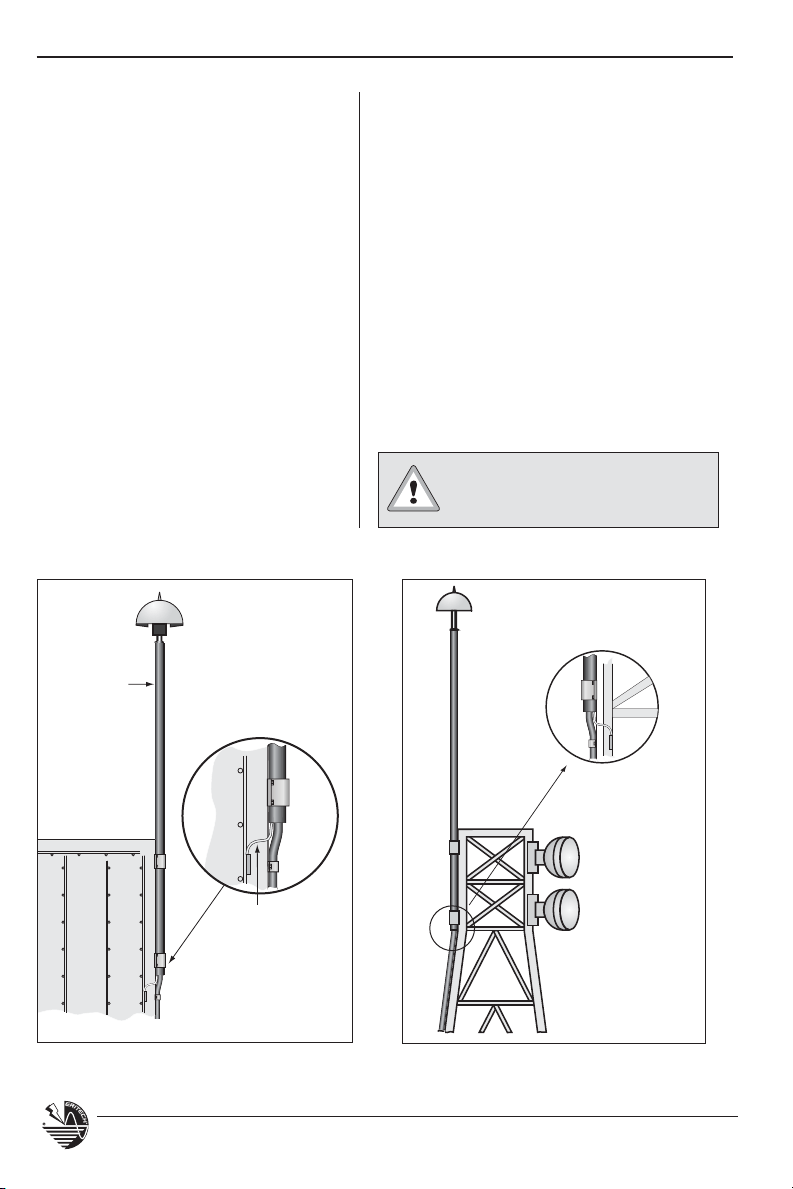
Structure Bonding Braid
To help ensure that the upper end of the
downconductor can be adequately electrically
bonded to the structure, a Structure Bonding
Braid has been provided at the base of the upper
termination of the downconductor. This braid is
a 75 mm (3 in.) tail which exits from under the
termination coldshrink and is
connector to allow connection
(8 AWG) copper cable (as mentioned in the
following text). This must be connected to a
conductive structural point to relieve the electrical
stresses on the downconductor and masonry
surfaces.
The use of the Structure
Bonding Braid is NOT optional,
and MUST always be used.
supplied with a
to a 6 mm2
Structure bonding
cable connected
to structural steel
Figure 13(a): Cantilevered FRP section on building.
Figure 13(b): Cantilevered FRP section on Radio Tower.
20
www.erico.com
Page 23

INSTALLATION, OPERATION AND MAINTENANCE MANUAL
After routing the downconductor,
it must be kept in constant physical
contact with the structure via
conduc
tive fixings as follows:
t The top 10% of the downconductor
from the terminal must be secured at
least every 1 m (40 in.). This includes
metallic mast sections.
t The lower 90% of the downconductor
must be secured at least every 2 m (80
in.).
t This includes routing inside any type of
conductive pipe or conduit, (see Fig. 17).
t When mechanical fastening of the
cable every 2 m (80 in) is not possible,
a maximum unsupported length of
35 m (114 ft) is allowed as long as the
installation adheres to the electrical
bonding requirements (see use of cable
ties in figure 17).
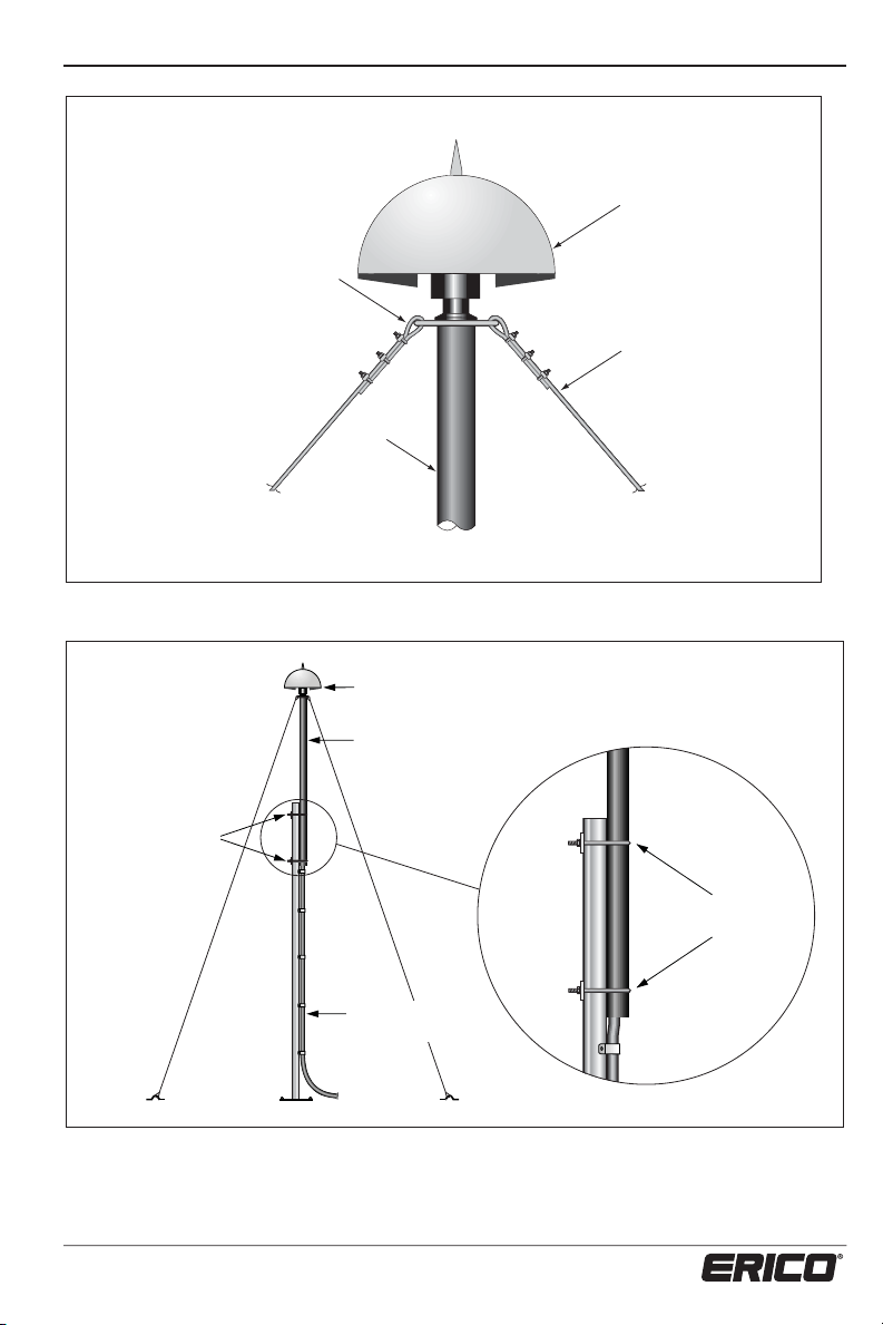
When using metallic lower
sections of mast (ie: aluminum),
then the downconductor MUST
be secured with ERITECH
of saddles to the mast at 1 m
(40 in.) intervals (max.). The
mast in turn must be electrically
bonded to the nearest conductive
structural point. In this case, the
structure bonding braid must
connect to the inline coupling,
(see Fig. 14).
Aluminum Mast
ERITECH
Saddles at
1 m (40 in.)
intervals
(max.)
®
brand
ERITECH
ERICORE
®
www.erico.com
To nearest conductive
structural point (steel
Figure 14: Connection of Structure Bonding
Braid in FRP and F.S. masts.
21
work, concrete
re-inforcing, etc)
Page 24

INSTALLATION, OPERATION AND MAINTENANCE MANUAL
Structural Steel Work
Figure 15: Connection of bonding cable to structural steel work.
Concrete Panel
To upper termination
kit bonding braid or
mast base
CADWELD®, bolted, or
other suitable electrically
bonded method
To upper termination kit
bonding braid or mast base
Structure bonding cable
CADWELD, bolted, or
other suitable electrically
bonding method
Figure 16: Connection of bonding cable to concrete reinforcing.
22
Reinforcing Steel
www.erico.com
Page 25
INSTALLATION, OPERATION AND MAINTENANCE MANUAL
2
The 6 mm
(8 AWG) copper cable used to
connect the structure bonding braid to the
structure must be one continuous length.
Joins in this cable would represent a
potential maintenance issue.
Any metallic surfaces that the downconductor may be secured to, if possible,
should be electrically connected to the
structural steel work.
Also, when using a metallic mast (ie: free
standing light pole), the structure bonding
braid must be connected to the top of the
metallic mast using 6 mm
2
(8 AWG)
insulated copper cable, (see figure 17).
To bond the downconductor inside a
conductive non-ferromagnetic mast pipe
or conduit, secure two stainless steel cable
ties around the downconductor at every
1 m (40 in.) or at 2 m (80 in.) intervals
with their tails left on, alligned at 180°
to each other so that when fed into
the pipe, they maintain contact with
the inside wall of the pipe, (see figure
17). The maximum length of the cable
installed inside the mast pipe or conduit
should not exceed 35 m (114 ft).
Metallic mast pipe or conduit
2 x stainless steel
cable ties at 180°
with tails left on
tructure bondin
cable attached to
top of freestandin
mast
reestandin metallic
mast where
downconductor
cannot be secured
to inside of mast
Figure 17: Electrical bonding of downconductor within metallic mast section or pipe.
www.erico.com
1 to 2 m (40-80 in.)
intervals as appropriate
Downconductor
23
Page 26

INSTALLATION, OPERATION AND MAINTENANCE MANUAL
®
Terminating the ERITECH
ERICORE Lower End
Instructions for ERITECH ERICORE Downconductor
The downconductor has been
specifically designed to cope
with extremely high impulse
voltages and currents. Due to the nature
of the downconductor construction, and
working environment, it is Very
its
Important
and carried out exactly as per the
following instructions.
that each step be followed
Tools required for Terminating Lower End of ERITECH ERICORE
1. Sharp Knife
2. Tape Measure
3. Flat Blade Screwdriver
4. Hacksaw
5. 150 mm (6 in.) Adjustable Spanner / Wrench
6. Roll Spring - (supplied with Upper Termination Kit)
7. Insulation Cutting Tool - (supplied with Upper Termination Kit)
8. Crimper (90 mm
2
) (only required if the cable lug is to be used)
The downconductor can be lugged, (as
detailed overleaf) and then connected
to the ground rod using the ground rod
clamp, or alternatively, it can simply be
connected to the ground rod using only
the ground rod clamp.
The Lower Termination Kit Consists of:
1 x Hose Clamp
2
1 x 90 mm
1 x 2.5 mm
1 x ‘U’ Bolt type Ground Rod Clamp (13-15 mm,
Lug
2
x 105 mm (12 AWG x 4 1⁄8 in.) Bare Copper Wire
1
1 x Water Proofing Mastic
1 x Vital Warning Label
2 x Rubber Gloves
1 x Instructions
24
⁄2 - 5⁄8 in. Rod Diameter.)
www.erico.com
Page 27

INSTALLATION, OPERATION AND MAINTENANCE MANUAL
Refer to Figure 18 for the following
instructions (1 to 10).
1. With the hacksaw (or appropriate
cutters), cut the downconductor cable to
length, leaving enough cable to be able to
easily and directly route it to the ground
termination.
2. At a distance of 100 mm (4 in.) from
the end of the cable, carefully cut a shallow
notch into the black outer insulation, no
deeper than 1 mm, (
3
⁄64 in.). Using the
insulation cutting tool, cut around the
circumference of the black outer insulation
until the copper screen underneath is
exposed.
Important! The insulation
cutting tool uses friction to cut
into the sheath and is less likely
to damage the layers underneath than using a knife.
3. Use a knife to carefully cut along the 100
mm (4 in.) length of black outer insulation
to a depth of no more than 1 mm. (
3
⁄64 in.).
Be careful not to cut too deeply so that the
copper layer underneath is not exposed
or damaged. Starting from the end of the
cable, carefully remove the outer insulation
and discard.
4. Carefully clean up the insulation
friction cut, removing any burrs for a neat
finish.
5
5. Fit the roll spring 15 mm (
⁄8 in.) from
the end of the outer insulation over the
exposed copper tape (roll spring supplied
with upper termination kit).
6. Remove the copper tape up to the roll
spring (exposing black triple extrusion
layers) by unrolling, then tearing the tape
up and back over the edge of the roll
spring at about a 45º angle. If necessary,
cut about 6 mm (
1
⁄4 in.) of the copper
tape up against the roll spring with a
knife and then tear over the spring.
2
7. Wrap one end of the 2.5 mm
105 mm (12 AWG x 4
1
⁄8 in.) bare copper
x
wire (supplied with the kit) around the
hose clamp, then fix the hose clamp over
the exposed copper screen of the downconductor and tighten with a screwdriver.
3
8. At 85 mm (3
⁄8 in.) from the end of
the cable, carefully cut around the
circumference of the black triple extrusion
layers with a knife, then, from the first
cut, along the length of the insulation to
the end of the cable. Remove the layers
and discard.
85 mm (33/8 in.) 15 mm (5/8 in.)
Copper Strands
and Double Tape Layer
Figure 18: Stripping lengths downconductor.
www.erico.com
Copper Tape Black
Outer Sheath
Compression Lug
25
2
2.5 mm
Copper Wire
Copper Strands and
Double Tape Layer
Hose Clamp
Copper Tape Black
Outer Sheath
Page 28
INSTALLATION, OPERATION AND MAINTENANCE MANUAL
9. Lay back all of the copper strands and
tape cut off the filler core with a hacksaw
or knife as close to the strands and tape
as possible without damaging them. Lay
the copper strands and tape neatly and
uniformly back in place.
10. If using the compression lug, combine
the end of the 2.5 mm
2
(12 AWG) bare
copper wire from the hose clamp with the
downconductors’ copper strands and then
fit ALL conductors into the 90 mm
2
lug
supplied with the kit. Make sure that it is
fitted correctly before crimping with an
appropriate crimper.
11. S
ecurely connect the lugged down-
conductor to the grounding system.
12. If the ‘U’ bolt ground rod clamp (or
other method) is to be used, then ensure
that the 2.5 mm
2
(12 AWG) bare copper
Lower termination shown lugged and
bolted to bus bar within enclosure
System 3000
ERITECH
wire from the hose clamp is bonded with
the final grounding connection and all of
the other downconductor copper strands
and tape. Then securely tighten the whole
connection.
Note: The ground rod clamp supplied in
this kit must be tightened to 44Nm
(32 lbf.ft.).
13. Make sure the lower termination is
free of moisture. Using rubber gloves,
shape the waterproofing mastic (supplied)
around all of the exposed areas of the
lower termination.
Note: Depending on the environment of
the lower termination, it may be necessary
to wrap a sealing tape or mastic around
the waterproofing mastic to stop it from
drying out over time.
Lower termination
shown connected
to rod with clamp
®
ERICORE
ERITECH ERICORE
LC
Hose Clamp
2.5 mm
(12 AWG)
Copper Wire
Compression
Lug
Copper
Bus Bar
To Grounding System
Figure 19: Termination to bus bar and ground rod.
Copper Tape
26
ntire loer
termination
to e ound
in aterprooing
masti
od Clamp
Ground od
www.erico.com
Page 29

INSTALLATION, OPERATION AND MAINTENANCE MANUAL
It is important to cover all
exposed metallic surfaces
(copper, hose clamp, lug,
ground rod clamp, etc.) To
avoid the risk of corrosion.
14. Place the ‘VITAL WARNING’ label
(supplied in the kit) in a suitable place near
the downconductor.
Note: If an upper termination has
already been performed on the cable,
then start with STEP 23 on page 37.
ERITECH
conductor cable has been
specifically designed to cope
®
ERICORE down-
with extremely high impulse
voltages and currents. Due
to the nature of the cable
construction, and its working
environment, it is very
important that each step
is followed and carried out
exactly as per the following
instructions.
The special insulation cutting tools have
been supplied to facilitate the cutting
of the cable’s insulation layers, while
preventing damage to other layers, such as
the copper foil.
Ground Pit
System 3000
LEC IV
Figure 20: Completed termination for downconductor.
www.erico.com
27
Downconductor
lower termination
bound in
waterproofing
mastic
ERITECH
Ground Rod
®
Page 30

INSTALLATION, OPERATION AND MAINTENANCE MANUAL
Terminating the ERITECH® ERICORE Upper End
Instructions for ERITECH® ERICORE Downconductor
Photo 2: Contents of upper termination kit and the tools required to complete the termination procedure.
Tools required for terminating upper end of ERITECH® ERICORE
1. Sharp Knife
2. Tape Measure
3. 2 x 375 mm (15 in.) Shifting Spanner / Wrench
4. PVC Electrical Tape
5. Roll Spring - supplied with termination kit
6. Insulation Cutting Tool - supplied with termination kit
The Upper Termination Kit consists of:
1 x Coldshrink Tube (red) 1 x Vital Warning Label 1 x Mastic Tape
1 x ERITECH ERICORE Coupling 1 x Structure Bonding Braid 1 x Instructions
(4 pieces when dismantled) 1 x Insulation Cutting Tool 1 x Crimp Lug
1 x Silicone Tape - 1.3 m (93 in.) 1 x Semi Conductive Tape 1 x Roll Clip
28
www.erico.com
Page 31

INSTALLATION, OPERATION AND MAINTENANCE MANUAL
The Insulation Cutting Tool uses
friction to cut into the sheath and is
less likely
under
to damage the layers
neath than using a knife. When
the instructions call for the knife to be
used, be sure not to cut any deeper
than instructed.
If the instructions are not followed correctly,
or if any of the insulation layers or the copper
foil are incorrectly cut, then the integrity of
the lightning protection is affected.
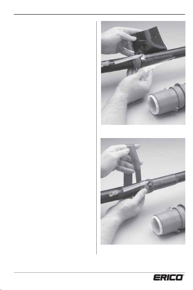
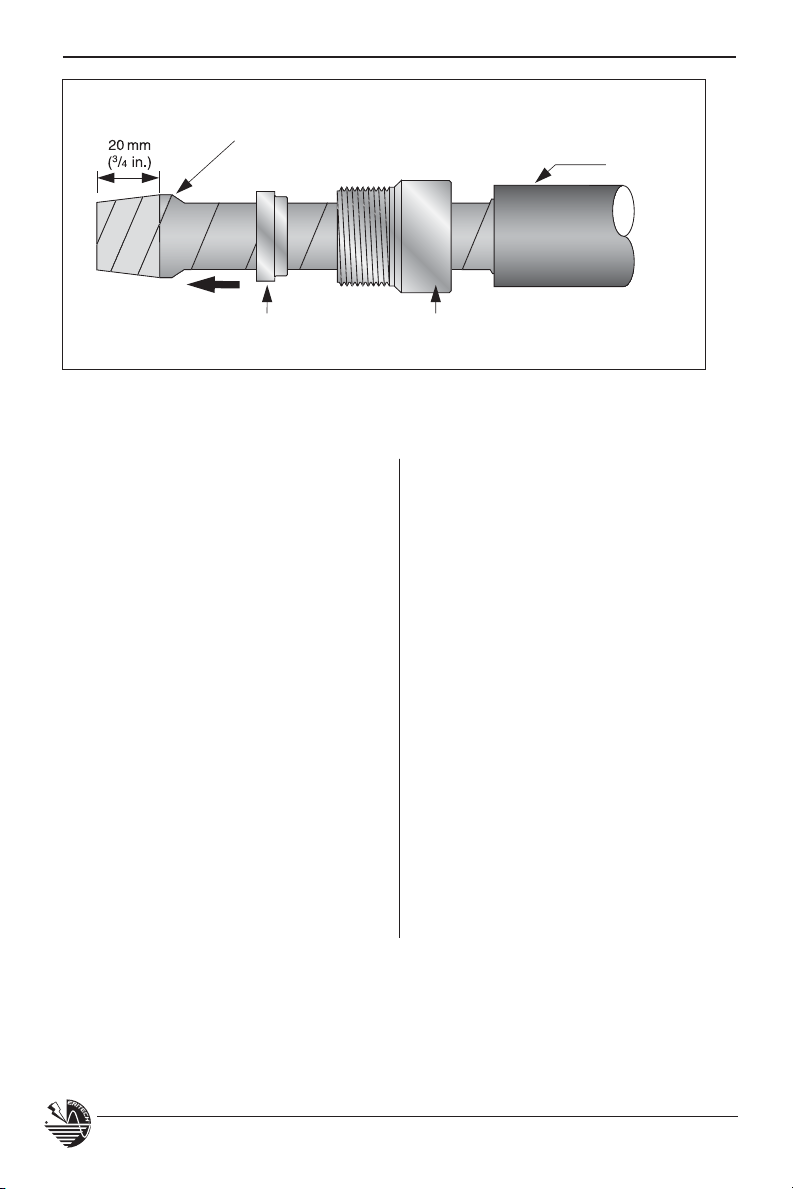
Refer to Figure 21 on page 36 for the
following instructions (1 to 11).
5
1. At a distance of 600 mm (23
⁄8 in.) from
the end of the cable, carefully cut a shallow
notch into the black outer insulation no
deeper than 1 mm, (
3
⁄64 in.). Then, using
the insulation cutting tool, cut around the
circumference of the black outer insulation
until the copper screen underneath is
exposed, (see photo 3).
2. Using a knife, carefully cut the outer
insulation of the cable to a depth of no
more than 1 mm (
600 mm (23
3
⁄64 in.), for the full
5
⁄8 in.), in the direction of the
end of the cable. Be sure not to cut so deep
as to expose or damage the copper layer
underneath. Starting from the end of the
cable, carefully remove the outer insulation
and discard.
Photo 3: Use of the insulation cutting tool to
cut the insulation without damaging the layers
beneath.
3. Carefully clean up the friction cut,
removing any burrs for a neat finish.
6
4. Fit the roll spring 20 mm (
⁄8 in.) from the
end of the outer insulation over the exposed
copper tape.
5. From the end of the cable, remove the
copper tape up to the roll spring, exposing
the black semi-conductive material by
unrolling, then tearing the tape up and back
over the edge of the roll spring at about a 45˚
angle. (If necessary, carefully cut about 6 mm
of the copper tape up against the roll spring
with a knife and then tear over the spring).
www.erico.com
29
Photo 4: Using the roll clip to cut and remove the
copper screen.
Page 32

INSTALLATION, OPERATION AND MAINTENANCE MANUAL
6. Carefully remove the roll spring, then
tape up the last 6 mm (
1
⁄4 in.) of the copper
tape with a piece of PVC tape, to stop
further unravelling.
7. Clean and degrease the outer sheath
for a distance of 100 mm (4 in.) from the
cut position. Using slight tension, wrap
one layer of sealant tape (red) around the
black outer insulation with a small overlap
of 5 mm (
1
⁄5 in.) over the copper tape
screen, (see photo 5).
8. Place the structure bond braid over
the cable so that it sits over the copper
screen and up against the sealant tape
(red). Ensure that the braid loops are tight
around the copper screen. Tape the bond
braid into place with PVC tape, (see
photo 6). (Ultimately, this braid may
require electrical bonding to the structure.)
3
9. At a distance 70 mm (2
⁄4 in.) from the
end of the cable, carefully cut a notch in
triple layered insulation no deeper than
3
⁄64 in.). Then using the insulation-
1 mm (
cutting tool, cut around the circumference
of the triple layered insulation until the
copper underneath is exposed.
Photo 5: Red sealant tape applied over overlap.
10. With a knife, carefully cut along the
70 mm (2 3⁄4 in.) length of triple layered
insulation
more than 1 mm
on the cable to a depth of no
(3⁄64 in.). Be sure not to
cut too deep, as to expose or damage the
copper layer underneath. Starting from
the end of the cable, carefully remove the
triple layered insulation and discard.
Photo 6: Bonding braid secured in place.
30
www.erico.com
Page 33
INSTALLATION, OPERATION AND MAINTENANCE MANUAL
11. Remove one release foil from the
stress control patch (green) and apply it
level with the outer insulation cut, against
the red sealant tape, (see photo 7). Wrap
the entire patch around the cable as
shown and remove the release foil during
installation. Avoid air pockets, wrinkles or
creases.
12. Wrap one layer of sealant tape (red)
with a small overlap and slight
over the braid wire and previously
tension
applied
sealant tape, below and level with the
(green) stress control patch, (see photo 8).
®
13. Take apart the ERITECH
ERICORE
coupling, ensuring there are 4 pieces.
There should be:
t"$PNQSFTTJPO/VU
t"$PNQSFTTJPO3JOH
t"$PNQSFTTJPO$POF
t".BJO$PVQMJOH1JFDF
14. Place the compression nut and
compression ring of the coupling set over
the strands and copper tape layer. Check
the order and orientation of the nut and
ring against Figure 22 on page 36.
Photo 7: Applying the stress control patch. In line with
initial outer layer cut and over the bonding braid.
15. Unwrap the material double tape layer
back to the compression ring. Place the
compression cone between the filler core
and the copper strands as shown in Figure
22. The cone should be “pushed on” until
it is flush with the end of the filler core.
Neatly form the copper strands back over
the cone in their original order.
www.erico.com
Photo 8: Apply the sealant tape below the stress
control patch.
31
Page 34
INSTALLATION, OPERATION AND MAINTENANCE MANUAL
Wind Back Layers of Copper Tape
Over Copper Strands to the End
Compression Ring Compression Nut
Figure 23: The termination coupling is fitted to the downconductor
ready for the main coupling body to be fitted.
Coldshrink
16. Rewrap the outer double layer of
copper tape into place over the copper
strands. Push the compression ring back up
over the wrapped copper strands and up
against the cone, (see figure 23).
17. Fit the main coupling piece from the
coupling set carefully over the end of the
cable ensuring the cable is pushed up as
far as it will go into the coupling. Ensure
the copper strands are kept in place and
order. Screw the compression nut into
the coupling piece and tighten, using the
correct size spanners / wrenches.
18. At a distance of 100 mm (4 in.) from
the end of the cable, wrap one half-lapped
layer of semi-conductive tape around
the triple layer insulation with an overlap
towards the copper tape / copper strand
center conductor up to, but not over, the
compression coupling.
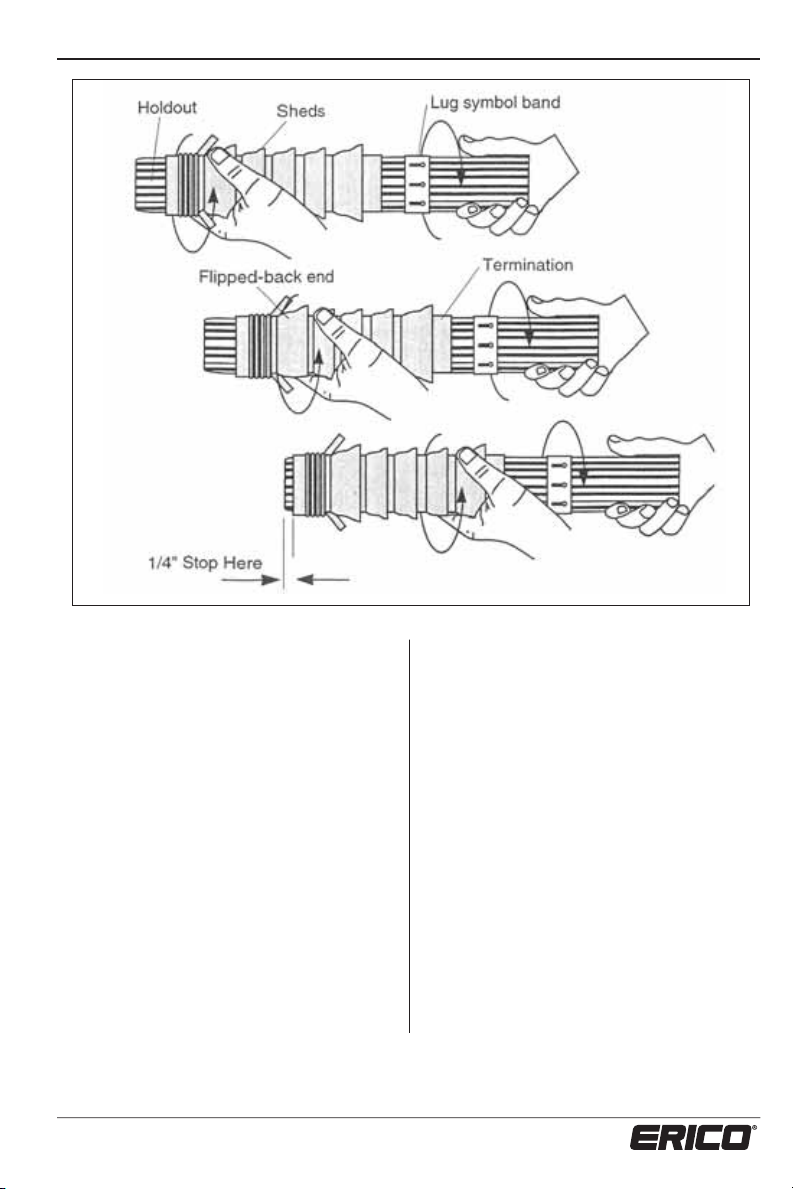
19. Loosening Termination
This operation is vital to the simple
installation of the product.
There are two terminations in this
kit, (one with three sheds, the other
with five). Loosen both in the manner
shown on page 33. Install the five
shed termination first.
Hold the termination in one hand and
the holdout in the other. Gripping
firmly, twist the termination and
holdout in opposite directions. Repeat
twisting the termination and holdout,
moving the hand in short increments
up the termination until the entire
termination is felt to move on the
holdout. Slide the termination until it
lines up with the end of the holdout
tube as shown. Note: Take care not
to slide the termination off the end
of the holdout. Stop the termination
about 6 mm (
1
⁄4 in) from the end of
the holdout.
32
www.erico.com
Page 35
INSTALLATION, OPERATION AND MAINTENANCE MANUAL
20. Installing the termination.
Position the holdout over the cable until
it meets the jacket cutback. Twist the
termination and slowly push it to the end
of the holdout.
Slide the termination off the holdout with
a twisting motion, holding the termination
that is on the holdout in one hand and
pulling the holdout with the other.
Note: Do NOT stretch the termination.
Do NOT hold the termination that is
partially installed and attempt to pull the
remaining termination off the holdout,
as this will stretch the termination and
generate an improperly installed termination
if not repositioned.
www.erico.com
Using the pull tabs, pull the flip-back
portion away from the main termination, at
the same time working the first two fingers
of each hand between the flip-back and
main termination. Pull the stretched out
flip-back over the cable jacket and sealant.
Make sure the termination length is in
accordance with the dimensions shown.
Having positioned the termination, now
wrap one layer tape sealant (red) over the
end of the termination and 6 mm (
onto the cable insulation as shown.
33
1
⁄4 in)
Page 36

INSTALLATION, OPERATION AND MAINTENANCE MANUAL
381 mm (15 in)
6 mm (1/4 in)
34
32 mm (1-1/4 in)
www.erico.com
Page 37

INSTALLATION, OPERATION AND MAINTENANCE MANUAL
21. Installing the termination (continued).
Slide the three-shedded termination over the cable until it meets the leading edge of the
sealant strip as shown. Twist the termination and slowly push it to the end of the holdout.
Slide the termination completely off the holdout using a twisting and pulling motion as shown.
Using the pull tabs, pull the flip-back portion away from the main termination, at the same time
working the first two fingers of each hand between the flip-back and main termination.
Pull the stretched out flip-back over the sealant.
www.erico.com
35
Page 38

70 mm (2
INSTALLATION, OPERATION AND MAINTENANCE MANUAL
600 mm (23 5/8 in.)
3
/4 in.)
380 mm (15 in.)
20 mm
6
(
/8 in.)
Copper
Conductor
Copper Strands and
Double Tape Layer
Figure 21: Cutting dimensions
Compression Cone Compression Ring
Copper Strands Splayed
Out to Allow Fitting of
Compression Cone
Filler Core (Black)
Figure 22: Positioning the compression coupling.
Triple Layered
Insulation Layer
PVC Tape to Stop Copper Tape from Unravelling
Compression Nut
Double Copper Tape Layer
Copper
Tape
Black Outer
Sheath
Wind Back Layers of Copper Tape
Over Copper Strands to the End
Compression Ring Compression Nut
Coldshrink
Figure 23: The termination coupling is fitted to the downconductor
ready for the main coupling body to be fitted.
36
www.erico.com
Page 39

INSTALLATION, OPERATION AND MAINTENANCE MANUAL
The coupling must be tightened
using spanners / wrenches, as
tightning by hands will not be
adequate.
22. Using the roll of silicone tape (grey),
overwrap half layers from 20 mm (
the end of the coldshrink to 30 mm (1
3
⁄4 in.) over
1
⁄8 in.)
over the coupling so that it covers the joint
between the main coupling and compression
nut, (refer to figure 24 on page 39).
Wrap with moderate tension (10 to 100%
stretch). Apply one final layer with no stretch.
Press down, to avoid the end lifting before
fusion of the tape takes place.
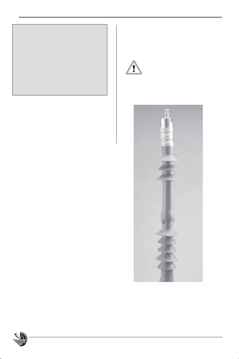
The finished termination must be
protected against any abrasion
and sharp edges during transport
or installation, as the coldshrink
tubes are susceptible to ripping or
tearing if nicked or scuffed.
23. The structure bonding braid MUST be
electrically connected via a 6 mm
2
(8 AWG)
length of insulated copper cable to the
specified conductive structural point, as
described in the ERITECH® SYSTEM 3000
Installation, Operation & Maintenance
Manual.
®
Connecting the ERITECH
DYNASPHERE
24. Feed the downconductor (and
structure bonding cable) through the
FRP mast so that the entire termination
is protruding from the top of the mast.
Remove
ERITECH
the lock screw in the base of the
®
DYNASPHERE
terminal, then
screw the terminal all the way onto the
termination coupling thread. Replace the
lock screw back into position so that it
locks the thread into place and will stop
the terminal from unscrewing.
25. Carefully pull the downconductor
(and structure bonding cable) back down
through the FRP mast so that the terminal
base sits correctly in the top of the mast.
Twist the FRP mast at least one complete
turn at the base of the terminal to remove
any stress on the termination sheds
(flanges) and to seat the terminal correctly.
www.erico.com
Photo 11: Installed compression coupling.
37
Page 40
INSTALLATION, OPERATION AND MAINTENANCE MANUAL
Note: It may be necessary to
pull back any slack of ERITECH
®
ERICORE downconductor through
the FRP support mast to achieve a
properly seated fit for the ERITECH
®
DYNASPHERE.
The ERITECH DYNASPHERE must
not be skewed and the base of the
terminal must be fully inserted into
the top of the mast.
2
26. Connect the 6 mm
bonding cable as detailed in the ERITECH
(8 AWG) structure
®
SYSTEM 3000 Installation, Operation
and Maintenance Manual. After bonding
the cable, ensure that the connection is
waterproof and resealed if required.
27. Place the Vital Warning Label in a
prominent position at the base of the mast,
or beside the downconductor at eye level,
if the installation is in an area where it is
possible for persons to gain access.
These termination procedures
should be strictly adhered to
since an incorrect termination
will result in failure of the
system.
38
Photo 12: Completed termination.
www.erico.com
Page 41

INSTALLATION, OPERATION AND MAINTENANCE MANUAL
30 mm
(1 1/4 in.)
Double Wrap Silicon Tape
Half Lapping Over Entire Length - Ensure Tape Covers Join in Coupling
40 mm
(1 1/2 in.)
20 mm
(3/4 in.)
Figure 24.
Photo 13: Once the ERITECH® DYNASPHERE has been
fitted to the termination coupling, ensure the locking
screw is tightened securely.
www.erico.com
Photo 14.
39
Page 42
INSTALLATION, OPERATION AND MAINTENANCE MANUAL
Terminals and Masts
Terminals
Once the terminal has been checked and
found to be in an acceptable condition
for installation, it can be attached to the
terminated downconductor as shown in the
Upper Termination instructions on page 37.
Please note, the serial number of each unit
will have been recorded in the Certificate
Of Compliance (inside back cover) in this
manual.
Masts
The selected mast configuration chosen must:
t
Elevate the terminal to the required
height as determined by the design
process (minimum height of 3 m
(10 ft.) above the highest point of the
structure).
t
Include a minimum of 2 m (80 in.) of
insulated mast material (FRP) immediately
below the air terminal.
t
Be suitably rated for local weather
conditions. It is advisable that guidance
from a local civil engineer be sought.
t
Be securely attached to the selected
mounting point(s).
t
Be guyed if applicable.
If the lower section of the mast
is conductive, ie. aluminum or
galvanized iron; then:
t *UNVTUCFFMFDUSJDBMMZCPOEFEUP
the nearest conductive structural
point. This may be either
structural steel work or concrete
reinforcing. Refer to page 20 for
details.
t 5IFEPXODPOEVDUPSNVTUCF
secured to the mast at 1 m (40
in.) intervals (max.).
Three basic types of mast configuration
include:
Guyed
t
Single length guyed - one section of
FRP (Fiberglass Reinforced Plastic)
mast material guyed at the top.
t
Double length guyed - two sections of
mast material, usually aluminum lower
and FRP upper, guyed between the two
sections and at the top.
Cantilevered
Used in situations where it is more practical
to mount without a base, eg: radio towers.
t At least one third of the lower mast
should be secured against the structure.
t Cantilevered masts can either be free
standing or guyed for extra stability.
Freestanding
Often used where the terminal, down-
conductor and grounding system are
isolated from volatile areas by installing the
ERITECH
away from those areas.
40
®
SYSTEM 3000 at least 5 m (17 ft.)
www.erico.com
Page 43

INSTALLATION, OPERATION AND MAINTENANCE MANUAL
Before the installation of the mast, ensure
that:
t
The free standing mast is supplied with
an appropriate spigot, suitable for either
internal or external mounting of the FRP
mast.
t
The downconductor is to be routed
internally or externally.
t
Provision is made for external or internal
mounting of LEC IV and access.
t
The downconductor is able to exit
through the base of the free standing
mast.
The free standing mast requirements for
foundations and erection are generally
handled by the mast manufacturers.
®
ERITECH
DYNASPHERE
2.0 m (81 in.) FRP
Inline Coupling
Mast Bases
ERICO supplies a range of aluminum bases
to suit:
t
ERITECH
base with an internal mast spigot).
t
Aluminum masts (welded directly onto
the required length of mast).
Both base types have downconductor
exit holes in the base, required if the
downconductor is to be routed inside of
the mast. They also have identical mounting
hole dimensions which are shown overleaf.
ERITECH
DYNASPHERE
4.6 m (15 ft.)
FRP (1/3 of
Mast Mounted
to Structure)
®
brand of FRP masts (aluminum
ERITECH
DYNASPHERE
2.0 m (81 in.) FRP
orge
Tn
ree ning
s
1.5 m (5 ft.)
luminum
s
Comms Tower
Figure 25: Guyed, Cantilevered and Free Standing Mast examples.
www.erico.com
41
5 m (1 ft.)
Page 44

INSTALLATION, OPERATION AND MAINTENANCE MANUAL
Figure 26: Base and mounting dimensions.
If an aluminum mast and
base are used and can not
be directly attached to the
structural steel work, or are
anchored to a concrete roof,
then they need to be directly
electrically bonded to the
closest structural steel work
or conductive structural point.
Refer to page 20.
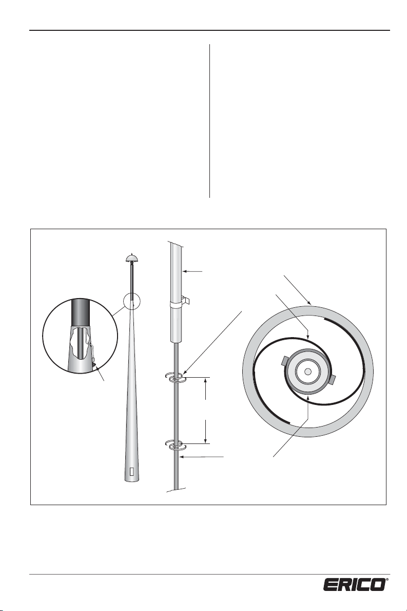
Mast Couplings and Guying
Points
There are two different methods of
coupling two sections of mast:
1. The U-Bolt set, which uses two stainless
steel U-bolts to clamp the two sections
of mast together, (see figure 28).
2. The Inline Coupling is designed to fit
between the upper and lower sections
of the masts and also provides three
guying anchor points, and, a downconductor exit point if required. The
maximum mast diameter that the Inline
Coupling is able to clamp onto is 70 mm
7
⁄8 in.) OD.
(2
On both the U-Bolts and Inline
Couplings, the nuts must not
be tightened to any more than
55kg/cm (45 in.lb).
Additional guying is
required at the top of 4.6 m
1
⁄2 ft.) FRP masts (if not
(15
mounted in a cantilevered
fashion). A guying ring is
supplied for guy anchor
points. This is installed
between the ERITECH
®
DYNASPHERE terminal and
the top of the mast, (see
figure 27).
42
www.erico.com
Page 45
INSTALLATION, OPERATION AND MAINTENANCE MANUAL
Guying Ring fitted
between ERITECH
DYNASPHERE
& FRP Mast
Figure 27: Use of Guying Ring.
U Bolts
®
FRP
Mast
ERITECH
DYNASPHERE
4.6 m (15 ft.) FRP
ERITECH
®
DYNASPHERE
Insuated Guying
®
Figure 28: Use of U-Bolts.
www.erico.com
5 m (1 ft.)
Amm t
43
U Bolts
Page 46
INSTALLATION, OPERATION AND MAINTENANCE MANUAL
Guying
1
ERICO has standard 4 m (13
7 m (24
of a
appropriate
1
⁄2 ft.) guying kits. If the guying
fiberglass mast is required, then the
guying kit should be selected
to suit the application. The guying material
is made up of light weight plastic coated
fiberglass, which is non-conductive.
If a customized guy kit has been supplied,
then the actual guy length can be
determined from the following:
Guy Length = 1.41 X
Where X = the vertical height between the
upper and lower guying points and the
assumed angle from horizontal is 45˚.
Important recommendations:
t 8IFOHVZJOHBOZNBTUJUJTBEWJTBCMF
that the guying angle be no greater
than 60° from horizontal.
t *UJTSFDPNNFOEFEUIBUNN
diameter stainless steel guying saddles
are used for the base guy anchor
points. If these are to be anchored to
a concrete surface, then 6 mm (
diameter x 40 mm (1
(minimum) masonry anchors or similar
should be used.
⁄2 ft.) and
5
⁄16 in.)
1
5
⁄8 in.) depth
⁄4 in.)
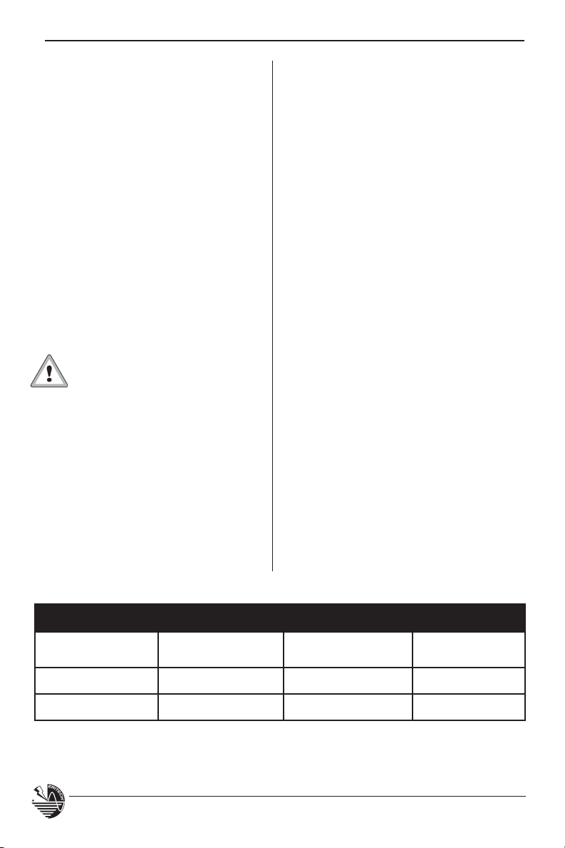
t &BDIPGUIFHVZJOHLJUTDPNFTXJUITJY
stainless steel thimbles to relieve stress
on the guys at the anchor points. These
thimbles MUST be used when guying,
(see figure 29).
3
t 8IFOVTJOHTIBDLMFTNN
⁄16 in.)
minimum), ensure that the shackle
pins are secured with nichrome wire.
When securing the fiberglass guys, use
the guying grips supplied in the guying
kit, carefully following the instructions
provided. Use of alternative wire rope
grips is acceptable but ensure that:
t (SJQTBSFNBEFPGBTVJUBCMFNBUFSJBMUP
PREVENT corrosion.
t 5IFSFBSFBNJOJNVNPGHSJQTQFSHVZ
end.
t (SJQTBSFTQBDFEBUBNJOJNVNPG
30 mm (1
1
⁄4 in.) on guys (or 6 x guy
diameter).
t (SJQTBSFDPSSFDUMZPSJFOUBUFEHSJQ
base (saddle) on the ‘Live’ side of the
guy and ‘U-bolt’ over the ‘Dead’ side or
tail of the guy.
t /PNPSFUIBOD/NMCGJOPG
torque is applied to the grip.
The above recommendations should also
be used for any other guying, ie: stainless
steel, when used on any mast.
Guy Kit Specifications
Guying Kit Guy Diameter
4 m Guy Kit 4 mm -
7 m Guy Kit 5 mm -
5
/32 in. 6 m - 20 1/2 ft. 430 Kg - 946 lb
3
/16 in. 10 m - 34 ft. 560 Kg - 1232 lb
44
Actual Guy
Length
Guy Tensile
Strength
www.erico.com
Page 47
INSTALLATION, OPERATION AND MAINTENANCE MANUAL
Minimum spacing
Fiberglass
30 mm (1
between Saddles
1
/4 in.) 30 mm (1 1/4 in.)
"Dead" End
Thimble
Figure 29: Correct methods of guying.
Saddle Base on "Live" End
Raising of Mast
When ready to raise the mast, check the
following:
t
Guys to the inline coupling, guying ring
or other mast anchor points are properly
secured.
t
Ensure the guys are not twisted, kinked
or damaged in any way.
t
Ensure that each guy can be easily
secured at the base when the mast has
been raised.
Turnbuckles or rigging screws are recommended at the base anchor points of the
guys to enable easy vertical alignment of
the mast and correct tensioning of the guys.
If using turn-buckles, ensure that they are
wired securely with nichrome wire.
Using conductive guying, such as stainless
steel, is acceptable as long as it is NOT
used for guying to the top of sections of
insulated FRP mast. Guying to the top of an
aluminum section of mast is acceptable.
"Live" Side
Remember to always Plan the Lift
before attempting it.
If the mast is to be raised by hand, ensure
that it can be safely and easily managed
manually.
It is recommended that the use of a crane
or other suitable equipment be used for
anything over 6 m (20 ft.) in height, or for
hazardous area installations such as high
elevations (towers).
To minimize the possibility of the mast
becoming bent or damaged, it is very
important to keep the mast straight during
the lift.
Ensure that:
t There are no overhead AC
power lines.
t There is nothing overhead that will
obstruct the lift.
t There is enough man-power available to
safely conduct the lift.
www.erico.com
t
There is only ONE person in control of
the lift.
45
Page 48

INSTALLATION, OPERATION AND MAINTENANCE MANUAL
n
t
Everyone involved in the lift knows
what has been planned and how the
lift is to be performed.
t
The mast is securely footed and cannot
move out of control during the lift.
t
Any guying has been properly secured
at the mast anchor points.
t
The downconductor has been correctly
terminated and the structure bonding
cable has been attached to the
termination.
t
The downconductor can not be
damaged at the base of the mast while
lifting, ie: if the cable exits from the
mast base it must be protected and not
used as the pivot point for the mast.
Maintain a minimum bending radius of
500 mm (20 in.).
eare o an overead poer lines or oter obstrctions
t
The mast can be easily and safely
secured at the base and guying points
immediately after it has been lifted
into position.
t
Any extra rigging that is required for
the lift only, can be removed after the
mast is in place.
It may be necessary to use a gin pole
arrangement to assist when lifting the mast,
especially if the mast is over 6 m (20 ft.) in
height or it is being lifted from a sloping
surface (typical arrangement shown below).
When using a crane to lift the mast into
position, ensure that:
t
The crane has enough weight and
height capacity to safely do the job.
t
There is nothing overhead that will
obstruct the lift.
ttac strctre
bonding braid
Figure 30: Removable gin pole to assist raising the mast.
ecre ging
Removable gin pole
and associated rigging
46
nsre te base ill
not slip dring te lit
rotect te R
RR rom abrasio
dring te lit
www.erico.com
Page 49

INSTALLATION, OPERATION AND MAINTENANCE MANUAL
t
Any guying has been properly secured at
the mast anchor points.
t
The downconductor has been correctly
terminated and the structure bonding
cable has been attached correctly.
t
The ERITECH® DYNASPHERE terminal is
NOT used as a slinging point.
t
When slinging the mast, ensure that the
slings or ropes can not foul the ERITECH
DYNASPHERE terminal.
t
When lifting the mast, the down-
conductor is tied off to the mast as
well to remove any strain on the downconductors termination to the ERITECH
DYNASPHERE terminal.
t
The downconductor can not be
damaged at the base of the mast while
lifting (maintain a minimum bending
radius of 500 mm (20 in.)) or can not
be damaged as a result of dragging
over rough or sharp surfaces during the
lift.
t
Any extra rigging that is required for
the lift only, can be removed after the
mast is in place.
t
The mast can be easily and safely
secured at its base and guying points
when it is lifted into position.
Do not sling
at base of
terminal
INCORRECT
Do not lift
with more than
5 m (17 ft.) of
Max 5 m
(17 ft.)
Figure 31: Incorrect and correct hauling methods.
www.erico.com
downconductor
hanging from
mast without
tying off to
mast.
47
Slung at
multiple points
CORRECT
Stress removed from upper
termination by securing
downconductor to lower mast
with flat webbing or other
appropriate sling.
Page 50

INSTALLATION, OPERATION AND MAINTENANCE MANUAL
Lightning Event Counter (LEC)
The LEC IV can be mounted at any point on
the downconductor or at the injection point
of the grounding system.
Refer to the instructions supplied with the
LEC IV when installing the unit.
Protective enclosure
When mounting the LEC IV, ensure that:
t
It is mounted in a secure area that is
not prone to contact with moving
objects, theft or vandalism.
t
It is not mounted in an area that is
prone to flooding.
t
The display can be easily viewed if
the LEC IV is mounted vertically and is
encased in a separate enclosure.
System 3
Counter
Clear window
LEC IV shown mounted
in an enclosure
Figure 32: LEC IV in protective enclosure with clear viewing window, for
easy counter reading.
48
www.erico.com
Page 51

INSTALLATION, OPERATION AND MAINTENANCE MANUAL
Long Lengths of ERITECH® ERICORE
Downconductor
Most installations can be conducted with a
single ERITECH
®
ERICORE downconductor
cable as described earlier in this manual.
However, where the installation involves
a long single length of ERITECH
®
ERICORE
cable, additional measures may need to be
taken to help ensure that the voltage build
up on the cable during a lightning strike
will not be excessive.
Proposed ERITECH® ERICORE length
Determine the thunderday level at
the proposed installation site.
Before considering these measures, it
needs to be determined if the cable is
too long to run in a single uninterrupted
length. The flowchart in Figure 33 allows
this to be determined. Starting with the
proposed ERITECH
®
ERICORE length as
indicated in the LPSD design, follow the
chart to the appropriate outcome. If a single length of ERITECH ERICORE is acceptable, no further consideration is required.
Figure 33: Determination of maximum single ERITECH ERICORE length.
www.erico.com
49
Page 52
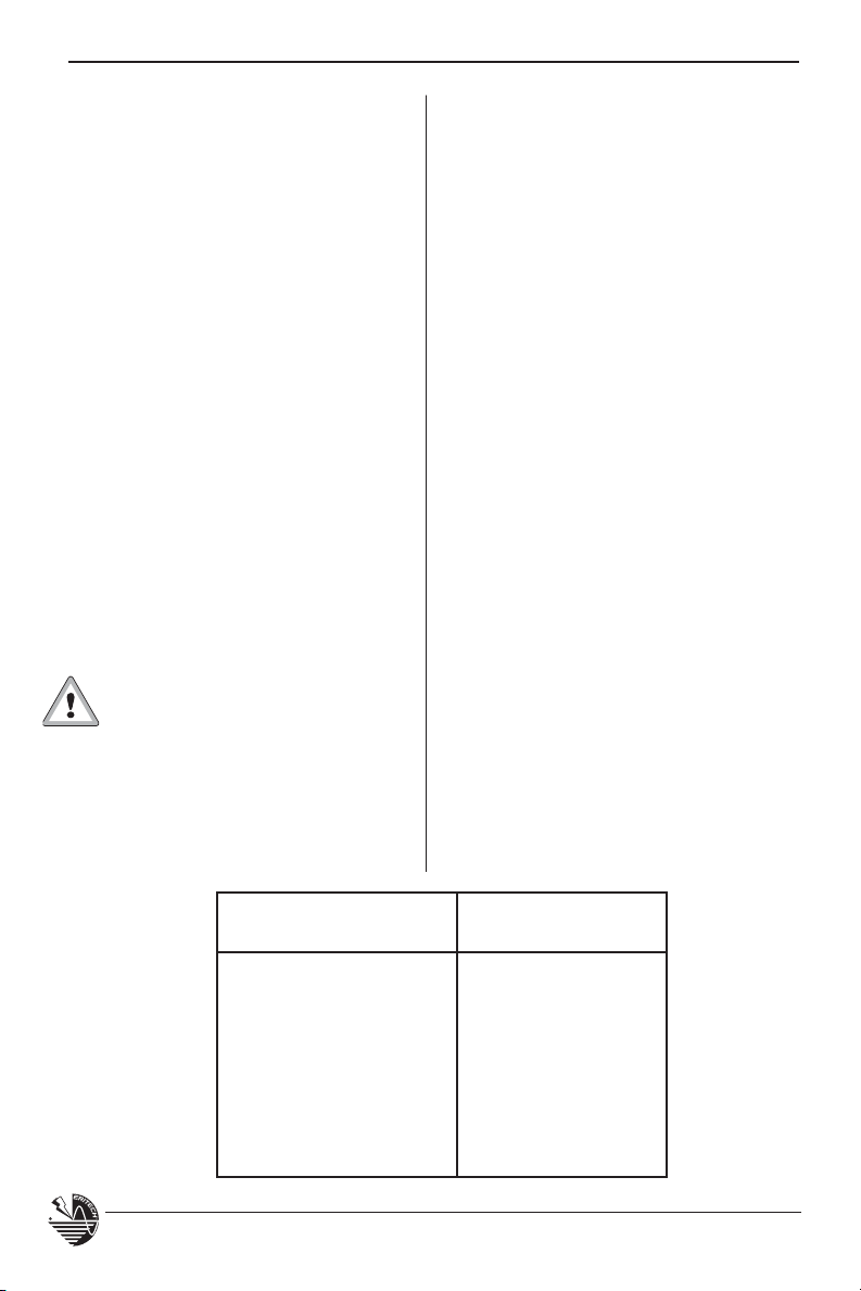
INSTALLATION, OPERATION AND MAINTENANCE MANUAL
However, if the result indicates that
additional measures are required, then a
single uninterrupted length of ERITECH
®
ERICORE cannot be run.
Although the flowchart allows lengths
of up to 87 m, ideally lengths should be
limited to 70 m to avoid any likelihood of
problems.
When determining the apparent length of
ERITECH
®
ERICORE conductor required in
a particular situation it is prudent to make
the connection to the ground system at
the first available opportunity. The practice of running ERITECH ERICORE for long
horizontal lengths at the ground level to
reach a designated earth point is discouraged. Instead a lower termination should
be made to a suitable earthing point upon
reaching the ground or basement level,
then a separate length of conventional
grounding bonding conductor run to other
earthing points as required.
In the case of installations exceeding the maximum single ERITECH
ERICORE cable length, the advice of
the ERICO application engineering group
should be sought. The following information on the techniques used is intended as
a guide for installers and to provide background information.
Note: If the number of thunderdays
for the proposed installation site is
not known, but the ground flash
density is known, this value can be
converted to thunderdays using the
following table. This resulting value
can then be used in the figure 33.
When additional measures are required,
there are two basic approaches to reducing the otherwise unacceptable voltage
rise that would occur on the cable:
t3VOQBSBMMFM&3*5&$)&3*$03&DBCMFT
or
®
t3VOBTJOHMF&3*5&$)
ERICORE cable,
but break it into several sections, none
of which exceeds the cable breakdown
voltage. This is done by periodically
connecting the cable to a conductive
structural point.
These methods are explained as follows.
Ground flash density
(strikes / km2 / year)
Up to 2.7 20
2.8 to 3.9 30
4.0 to 5.2 40
5.3 to 6.6 50
6.7 to 9.5 60
9.6 to 12.5 80
12.6 or more 100
50
Lightning activity
(thunderdays / year)
www.erico.com
Page 53

INSTALLATION, OPERATION AND MAINTENANCE MANUAL
Parallel ERITECH® ERICORE cables
Running two or more parallel cables
reduces the voltage rise on each cable
by reducing the current magnitude flowing in each cable. For example, if three
cables were run in parallel, each cable
could be three times the single length.
In practice, however, this technique is
generally only economically viable when
running two cable sections in parallel.
ERICO has developed a special hardware
arrangement to allow this to occur, as
illustrated in Figure 34.
®
ERITECH
DYNASPHERE
ERITECH® ERICORE
Fixing Bolts
Main Plate
Top Fixing Bolt
Mast Sleeve Adaptor
Locking Screw
Mast Butt Adaptor
Compression Couplings
E2 ERITECH
ERITECH® ERICORE Cable and
Upper Terminations
®
ERICORE
The dual coupling termination allows the
ERITECH
connect to two ERITECH
®
DYNASPHERE air terminal to
®
ERICORE cables,
each complete with upper terminations
and FRP masts. All the rules that normally apply to a single ERITECH ERICORE
arrangement apply to these two cables
and mast arrangement.
A typical mast arrangement is shown in
Figure 35. The normal u-bolts are used to
fix the FRP masts to the aluminum mast,
and the conductive saddles are used to fix
the ERITECH
®
ERICORE to the mast at the
normal interval of at least every 1 meter
(40 in.). Note that the center mast and
the two FRP sections will not be
completely in line when the FRP masts
are correctly spaced.
Depending on the mast height required,
either the 2 meter, or the 4.6 meter, FRP
mast may be used.
These items are
only included in
item ‘TERMDUALCOUP’,
remaining items
are shown for
field assembly
purposes only.
www.erico.com
FRP Masts
Figure 34: Exploded view of the Dual Coupling Termination.
51
Page 54

INSTALLATION, OPERATION AND MAINTENANCE MANUAL
IMPORTANT – To maintain the
necessary clearance between
the ERITECH
®
DYNASPHERE air
terminal and the top of the mast, the
FRP mast must protrude at least
1400 mm above the top of the
aluminum mast. The following shows
the required positioning dimensions for
the two available FRP mast sizes.
2 meter FRP Mast
Overlap on aluminum mast = 600 mm
Protrusion above aluminum mast = 1400 mm
4.6 meter FRP Mast
Overlap on aluminum mast = 1.5 m
Protrusion above aluminum mast = 3.1 m
The standard guy ring part may be fitted to
the Dual Coupling Termination and used
with the usual guying kit.
Guy Ring
®
ERITECH
1 x TERMDUALCOUP
Guy Kit
DYNASPHERE
2 x FRP Mast
(2 m or 4.6 m)
The twin ERITECH® ERICORE conductors
are run in a parallel manner down to
ground (see Figure 36). The usual
conductive saddle spacing applies.
At the point of connection to the
grounding system, each ERITECH
®
ERICORE cable is fitted with an ERITECH
ERICORE lower termination kit, and
attached to the grounding system
Series connected ERITECH®
ERICORE cable sections
As an alternative to running twin
ERITECH ERICORE conductors, a single
ERITECH ERICORE cable can be run, but
it is broken into several sections, none
of which exceeds the cable breakdown
voltage. This is done by periodically
connecting the cable to a conductive
structural point (see Figure 37).
ERICORE
Cable
®
Aluminum Mast
2 x ERITECH
Figure 35: Typical mast arrangement using the twin ERITECH® ERICORE arrangement.
52
U Bolts
www.erico.com
Page 55
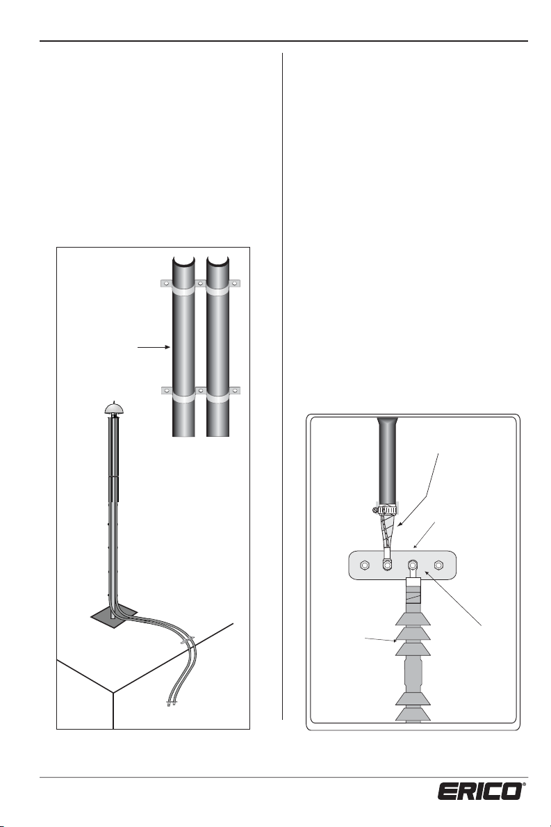
INSTALLATION, OPERATION AND MAINTENANCE MANUAL
The lower end of the upper cable section
is fitted with a lower termination, and
the upper end of the lower cable section
is fitted with an upper termination. The
lower termination inherently has a lug
termination, but the upper termination
needs to be fitted with a bonding
termination (ERICORE/UTSP) and lug
(termlugcoup) to allow it to be lugged.
Each of these two lugged terminations
must be electrically bolted together and
to a suitable conductive structural point.
2 x ERITECH®
ERICORE
Running in
Parallel
In some installations, both lugs can be
directly connected to a suitable
conductive structural point, but in some
installations it will be more convenient to
connect both lugs to a small busbar, and
have this busbar connected to a suitable
nearby conductive structural point. Note
that the conductor used in this case must
be a minimum of 16 mm
2
(4 AWG) and
should not exceed 5 m (200 in) in length. A
suitable conductive structural point may be
either structural steel work or the
reinforcing within concrete panels or slabs.
These joints should not be exposed to the
weather and are usually located in a
service shaft. Very tall buildings will have a
number of connection points depending on
their height.
Details of where to provide the joint will
be provided by the ERICO application
engineers, after consideration of the
building details.
®
ERITECH
ERICORE
Lower
Termination
Figure 36: The twin ERITECH ERICORE conductors
are run parallel down to the ground.
www.erico.com
Busbar connected
to conductive
structural point
®
ERITECH
ERICORE Upper
Termination
Figure 37: The method of joining ERITECH ERICORE
sections.
Upper Termination
Lug Coupling
53
Page 56

INSTALLATION, OPERATION AND MAINTENANCE MANUAL
Removal of Structural Bonding Braid
cut off as far back as possible. Then the
coldshrink is rolled back in place, covering
the freshly cut braid. Discard the cut off
braid and terminal block.
Alternative attachment of
upper termination to busbar
The upper terminations on all lower
sections of ERITECH
®
ERICORE cable are to
have the structural bonding braids removed.
The following diagram indicates how this is
done. The cold shrink is rolled back as far as
possible, and the structural bonding braid
Practical examples for Long
®
When to use a twin ERITECH
ERICORE
arrangement or a series connected
arrangement depends on the particular
circumstance. The following examples
give typical guidance.
Telecom Towers
Most towers would be less than 70 m,
or so, in height so that a single ERITECH
ERICORE downconductor would suffice.
However, where the tower is over the
maximum single length but less than twice
the maximum single length (typically 70 m
(230 ft) to 140 m (460 ft) in height), it is
preferable to run twin ERITECH
®
ERICORE
downconductors. These conductors should
ideally run down opposite legs of the tower
and each connect into the ring earth at the
base of the tower.
Alternatively, and less preferably, a
single upper section of typical length
70 m (230 ft) could be run from the top
of the tower to a point lower down on the
tower, then bonded to the tower using a
waterproofed lower termination. A conventional lightning downconductor could be
run from this point down to the base of the
®
If an upper termination lug coupling is not
available, a TERMLUGCOUPL may be used
in conjunction with a coupling tube (part:
ERICOREUTSP) as shown here.
Lengths of ERITECH® ERICORE
tower. This arrangement helps ensure that
the lightning current bypasses the sensitive tower mounted electronics mounted
in the antennas on the top half of the
tower.
Buildings
Buildings less than 70 m (230 ft), or so,
in height are served by a single ERITECH
ERICORE downconductor.
Buildings of height over the maximum
single length but less than twice the
maximum single length (typically 70 m
(230 ft) to 140 m (460 ft) in height) may
be installed with either twin ERITECH
ERICORE down-conductors, or a series
connection in the service shaft.
Buildings of height greater than twice the
maximum single length (typically greater
than 140 m (460 ft) in height) need to
use the series connection method. The
ERICO application engineering group will
determine the allowable lengths of the
lower cable sections, which may be able
to be longer than the upper length, and
in some cases, the lower sections may be
conventional downconductor.
®
®
54
www.erico.com
Page 57

INSTALLATION, OPERATION AND MAINTENANCE MANUAL
Certification
The certification of the ERITECH® SYSTEM
3000 installation must be performed by an
authorized ERICO representative.
This is done in conjunction with issuing of a
Certificate of Compliance, which is supplied
in the back of this manual.
When this certificate has been completed
and signed, a copy must be either taken
by the ERICO representative or sent to the
nearest ERICO office.
During the process of certification, the
following will be checked:
t
Installation matches the originally
approved design.
t
Installation needs to be registered at
www.erico.com.
t
The integrity of the mast and any
associated brackets and fastenings.
Operation and Maintenance
The ERITECH SYSTEM 3000 lightning
protection system requires no user
operation and is completely automatic in
operation.
t
The ERITECH® DYNASPHERE becomes
active only during storm activity.
t
The system does not require any external
power requirements or replacement
components for normal operation.
t
Guying, anchor points and fastenings.
t
Downconductor routing, securing and
seals.
t
Ground termination of downconductor.
t
Grounding System.
t
Labelling.
t
Completion of Maintenance Records in
this manual.
t
Certificate of Compliance and web site
registration completed.
t
General mechanical check of all
fastenings.
Maintenance should be undertaken:
t
After each known strike to the
ERITECH DYNASPHERE.
t
At least once per year.
t
If any changes have been made to the
structure, whether they be structural,
antennae or building maintenance unit
additions, etc.
t
It is essential that the ERITECH SYSTEM
3000 Lightning Protection System be
regularly maintained.
www.erico.com
Use the maintenance record table on page
58 to record the relevant details. These
records and manual should be kept in a
safe place near the installation.
55
Page 58

INSTALLATION, OPERATION AND MAINTENANCE MANUAL
Maintenance should be undertaken as
follows:
Do not attempt maintenance
during potential lightning
periods.
1. Check that the building is the same
physical shape and that no additional
structures such as antennae, advertising
signs, satellite dishes, building
maintenance
installed within 3 m (121 in.) height of
the ERITECH
2. Inspect the ERITECH DYNASPHERE to
ensure that it is not dented or physically
damaged in any way.
3. Inspect the finial tip on top of the
ERITECH DYNASPHERE to ensure that
it is not excessively burnt, deformed or
missing. A finial tip must be replaced
if more than 6 mm (
missing.
4. Check that the FRP mast and lower
mast assembly is securely attached
to the structure. Check that the guys
are secure and undamaged. Replace if
necessary. Check that all fastenings are
secure and tight.
5. If connected, check the structure
bonding cable from the upper
termination or mast base is securely
connected to the structural steel work.
6. Look for signs of damage to the
ERITECH
(whether by lightning, careless handling,
vandalism or other causes). Check that
the downconductor is inaccessible to
people and machinery.
7. Check that all labels and signs are still
attached and clearly legible. These labels
MUST be in place. Refer to the section
on Labelling.
units or similar have been
®
DYNASPHERE.
1
/4 in.) of the tip is
®
ERICORE downconductor
8. Check that the Lightning Event Counter
(LEC) is secure, and that the display is
registering a reading, then record the
reading.
9. Record resistance and continuity
measurements using figure 38 and the
table on page 57.
These measurements should be performed
after a known strike to the terminal.
t
Remove the waterproofing mastic from
the lower termination to expose the
connection.
t
Disconnect the downconductor from the
grounding system.
t
If possible, disconnect the structure
ground bonding cable from the
grounding system.
t
Measure the ground resistance of the
lightning protection grounding system
and record in column 1 of ground
resistance readings.
t
Measure the ground resistance of the
structure and record in column 2 of
ground resistance readings.
t
Reconnect the structure ground bonding
cable to the lightning protection ground
system, then measure & record in
column 3 of ground resistance readings.
t
At the lower termination of the
downconductor, disconnect the
2
2.5 mm
from under the hose clamp.
t
With a multimeter, measure the
continuity between the center
conductor and the copper screen of the
downconductor.
than 1,000 ohms).
(12 AWG) bonding wire
(This should be greater
56
www.erico.com
Page 59

INSTALLATION, OPERATION AND MAINTENANCE MANUAL
t
If possible, measure the continuity
between
and upper
(this should be low ohms).
t
Reconnect the 2.5 mm2 (12 AWG)
bonding wire to the hose clamp.
t
Reconnect the downconductor lower
termination and structure ground
bonding cable to the lightning protection
grounding system.
t
Reseal the lower termination and
grounding connection in waterproofing
mastic and ensure that the whole
connection is made waterproof.
the center conductor at the lower
end of the downconductor,
10. Report any problems, defects of
inconsistencies to your nearest ERICO
Distributor.
11. ERICO maintains a database of
statistical information concerning
ERITECH
We encourage copies of the initial
maintenance records be sent to ERICO
for collation into our database.
These records should include:
t
t
t
t
t
t
®
SYSTEM 3000 installations.
Name and location of the structure
Installation date
Building height
Maintenance inspection date
Latest lightning event counter reading
The Certificate of Compliance
Lightning Protection
Downconductor (Disconnec
Lightning Protection Ground)
ted from
Lightning Protection
Grounding System
Figure 38: Grounding and downconductor continuity testing.
www.erico.com
57
Structure Bonding Cable
(Disconnected from Lightning
Protection Ground)
Page 60
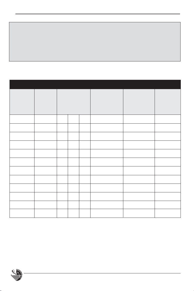
INSTALLATION, OPERATION AND MAINTENANCE MANUAL
NOTICE
Users are advised that the
ERITECH®
SYSTEM 3000 Lightning Protection System
may not function to its full efficiency under ice or snow conditions or on
chimneys or stacks emitting gasses or pollutants. For advice on temperature or
corrosion concerns, please contact your local ERICO Distributor.
MAINTENANCE RECORD
Lightning Ground Check of
Date of Event Resistance Maintenance Comments Inspected
Inspection Counter Readings Points 1 to 11 by
Reading
1 2 3
58
www.erico.com
Page 61
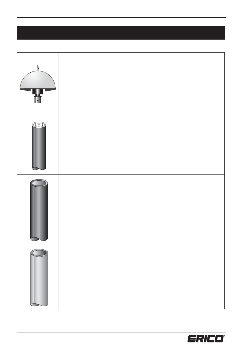
INSTALLATION, OPERATION AND MAINTENANCE MANUAL
Specifications
ERITECH® DYNASPHERE Enhanced Terminal
Capture point of the ERITECH® SYSTEM 3000. Initiates an upward leader
during storm conditions to attract lightning discharges over a greater
radius than conventional protection.
1
7
/16”)
/2 in.)
2
(1/0 AWG) main conductor
1
/2 in.) & 4.6 m (187 3/4 in.)
3
/8 in.)
11
/16 in.)
1
/4 lbs.)
3
/4 lbs.)
Height: 140 mm (5
Diameter: 255 mm (10 in.)
Weight: 2.8 kg (6 lbs.)
Color/Finish: Brushed Stainless Steel
ERITECH® ERICORE Downconductor
Purpose designed cables, using a copper 50 mm
to safely convey the lightning energy to ground, while minimizing side
flashing.
Diameter: 36 mm (1
Weight: 1.2 kg / m
13 oz / ft.
FRP Mast
Purpose designed Fiberglass Reinforced Plastic, manufactured from nonhydroscopic epoxy and glass laminate, provides an insulated mast for
mounting the ERITECH
®
DYNASPHERE.
Lengths: 2 m (81
Inside Diameter: 60 mm (2
Outside Diameter: 68 mm (2
Weight: 2 m = 3.3 kg (7
4.6 m = 7.6 kg (16
Color/Finish: Black
www.erico.com
Aluminum Mast
Light weight lower mast material.
Lengths: 3, 4, 5 & 6 m
(122
Inside diameter: 61.9 mm (2
Outside diameter: 69.9 mm (2
1
/2, 163 1/4, 204 & 245 in.)
7
/16 in)
3
/4 in.)
Weight: 2.4 kg / meter
Available with or without mast base plate.
59
Page 62

INSTALLATION, OPERATION AND MAINTENANCE MANUAL
Inline Coupling
Purpose designed coupling to clamp FRP to aluminum lower mast,
providing 3 guy anchoring points and downconductor exit point.
7
Max. Clamping diameter: 70 mm (2
Max. Clamping torque: 55 kg/cm (45 in.lb)
Weight: 2.4 kg (5
Height added to mast: 200 mm (7
/8 in.)
1
/4 lbs.)
7
/8 in.)
Lightning Event Counter (LEC IV)
Purpose designed lightning event counter.
I.P. Rating: IP67
Operating Temp. Range: 40˚C to +50˚C (-40˚F to 122˚F)
Dimensions: 110 mm(h) x 80 mm(w) x 90 mm(d)
4
11
/32 (h) x 3 5/32 (w) x 2 7/8 (d)
Weight: 0.4 kg
Terminal Lug Coupling
The terminal lug coupling allows for connection of a conventional
downconductor such as 25 mm x 3 mm copper tape / bar to the
®
ERITECH
DYNASPHERE. See Upper Termination Instructions for fixing
of coupling to ERITECH DYNASPHERE.
Material: Brass Alloy 384D
Length: 68.75 mm (2
11
/16 in.)
Weight: 181 grams (6.38 oz.)
Diameter: 25.4 mm (1 in.)
Guy Ring
Purpose designed guy ring, providing 3 guy anchoring points from the
neck of the ERITECH DYNASPHERE.
2
Height: 105.25 mm (4
Inside Diameter: 60 mm (2
Outside Diameter: 91 mm (3
Material: Cast Aluminum
Guy Hole Diameter: 10 mm (
60
6
/16 in.)
1
/2 in.)
6
/16 in.)
/16 in.)
www.erico.com
Page 63

INSTALLATION, OPERATION AND MAINTENANCE MANUAL
Guy Kit
Purpose designed guying kits for anchoring from a guy ring or
inline coupling. Each kit comes complete with six stainless steel
thimbles, plus 18 guying grips per kit. Refer to pages 44 and 45
for more detail.
4 m Guy Kit 7 m Guy Kit
Guy Diameter: 4 mm (
Actual Guy Length: 6 m (20
5
/32 in.) 5 mm (3/16 in.)
1
/2 ft.) 10 m (34 ft.)
Guy Tensile Strength: 430 kg (946 lb.) 560 kg (1232 lb.)
ERITECH® ERICORE Downconductor Saddles
Purpose designed saddles for securing of downconductor to
structure.
Material: Stainless Steel 316
Length: 114.5 mm (4
Thickness: 1.2 mm (
Fixing Hole Diameter: 6 mm (
1
/16 in.)
4
/16 in.)
1
/2 in.)
Width: 25.5 mm (1 in.)
www.erico.com
Stainless Steel Cable Tie
Purpose designed cable ties for securing of ERITECH ERICORE
downconductor to structures.
Length: 521 mm (20
Width: 7.9 mm (
1
5
/16 in.)
/2 in.)
Material: Stainless Steel
Maximum Bundle Diameter: 152 mm (6 in.)
Minimum Loop Tensile Strength: 250 lbs.
61
Page 64

INSTALLATION, OPERATION AND MAINTENANCE MANUAL
Glossary for terms used in this text
Securing
Saddles, cable hangers or clamps used to
mechanically and electrostatically secure the
downconductor to the structure.
Bond
Electrical connection between the outer
semi-conductive sheath of the downconductor and other electrically conductive
materials.
Clamp
Electrically conductive, mechanical anchoring
of the downconductor to the structure.
Conductive Structural Point
Any point of the structure that is electrically
conductive and is either connected to the
structure earth or has a substantial metallic
mass.
Fastenings
Bolts, screws, masonry anchors or other
hardware used to secure anchors to the
structure.
FRP
Fiberglass Reinforced Plastic. Insulated mast
for mounting ERITECH
®
DYNASPHERE.
Metallic Mast Section
Any type of electrically conductive mast
section, ie: aluminum masts, galvanized
free standing mast, etc.
Structure Bonding Braid
Conductive lead at the base of the upper
termination used to electrostatically bond
the downconductors’ outer sheath to a
conductive structural point if the downconductor cannot be clamped to a
conductive structural point within 5 m
(17 ft.) of the upper termination.
62
www.erico.com
Page 65

CERTIFICATE OF COMPLIANCE & WARRANTY REGISTRATION
www.erico.com
63
Page 66

STAMP
HERE
AFFIX
Page 67

www.erico.com
www.erico.com
10 YEAR LIMITED WARRANTY
This product has a limited warranty to be free from defects in materials and workmanship for a period
of ten (10) years from the date of dispatch from the Manufacturer. The Purchaser acknowledges that
lightning is a natural event with statistical variation in behavior and energy levels which may exceed
product ratings, and 100% protection is not offered and cannot be provided for. Therefore the
Manufacturer’s liability is limited to the repair or replacement of the product (at the Manufacturer’s sole
option) which in its judgement has not been abused, misused, interfered with by any person not
authorized by the Manufacturer, or exposed to energy or transient levels exceeding the Manufacturer’s
specifications for the product. The product must be installed and earthed (where applicable) in strict
accordance with the Manufacturer’s specifications and all relevant national Electricity and Safety
Standards. The Manufacturer and the Purchaser mutually acknowledge that the product by its nature
may be subject to degradation as a consequence of the number and severity of surges and transients
www.erico.com
that it experiences in normal use and this warranty excludes such gradual or sudden degradation. This
warranty does not indemnify the Purchaser of the product for any consequential claim for damages or
loss of operations or service or profits. Customers should contact their nearest ERICO agent to obtain a
Product Repair Authorization Number prior to making any claim under this warranty. This is only a
summary of the warranty given by the Manufacturer. The full text of the warranty is set out in the
Manufacturer’s Conditions of Quotation and Sale.
10 YEAR LIMITED WARRANTY
This product has a limited warranty to be free from defects in materials and workmanship for a period
of ten (10) years from the date of dispatch from the Manufacturer. The Purchaser acknowledges that
lightning is a natural event with statistical variation in behavior and energy levels which may exceed
product ratings, and 100% protection is not offered and cannot be provided for. Therefore the
Manufacturer’s liability is limited to the repair or replacement of the product (at the Manufacturer’s sole
option) which in its judgement has not been abused, misused, interfered with by any person not
authorized by the Manufacturer, or exposed to energy or transient levels exceeding the Manufacturer’s
specifications for the product. The product must be installed and earthed (where applicable) in strict
accordance with the Manufacturer’s specifications and all relevant national Electricity and Safety
Standards. The Manufacturer and the Purchaser mutually acknowledge that the product by its nature
may be subject to degradation as a consequence of the number and severity of surges and transients
that it experiences in normal use and this warranty excludes such gradual or sudden degradation. This
warranty does not indemnify the Purchaser of the product for any consequential claim for damages or
loss of operations or service or profits. Customers should contact their nearest ERICO agent to obtain a
Product Repair Authorization Number prior to making any claim under this warranty. This is only a
summary of the warranty given by the Manufacturer. The full text of the warranty is set out in the
Manufacturer’s Conditions of Quotation and Sale.
This product has a limited warranty to be free from defects in materials and workmanship for a period of
ten (10) years from the date of dispatch from the Manufacturer. The Purchaser acknowledges that
lightning is a natural event with statistical variation in behavior and energy levels which may exceed
product ratings, and 100% protection is not offered and cannot be provided for. Therefore the
Manufacturer’s liability is limited to the repair or replacement of the product (at the Manufacturer’s sole
option) which in its judgement has not been abused, misused, interfered with by any person not
authorized by the Manufacturer, or exposed to energy or transient levels exceeding the Manufacturer’s
specifications for the product. The product must be installed and earthed (where applicable) in strict
accordance with the Manufacturer’s specifications and all relevant national Electricity and Safety
Standards. The Manufacturer and the Purchaser mutually acknowledge that the product by its nature
may be subject to degradation as a consequence of the number and severity of surges and transients that
it experiences in normal use and this warranty excludes such gradual or sudden degradation. This
warranty does not indemnify the Purchaser of the product for any consequential claim for damages or
loss of operations or service or profits. Customers should contact their nearest ERICO agent to obtain a
Product Repair Authorization Number prior to making any claim under this warranty. This is only a
summary of the warranty given by the Manufacturer. The full text of the warranty is set out in the
Manufacturer’s Conditions of Quotation and Sale.
10 YEAR LIMITED WARRANTY
Page 68

www.erico.com
AUSTRALIA
Phone 1800-263-508
Fax 1800-423-091
BELGIUM
Phone 0800-757-48
Fax 0800-757-60
BRAZIL
Phone +55-11-3623-4333
Fax +55-11-3621-4066
CANADA
Phone +1-800-677-9089
Fax +1-800-677-8131
CHILE
Phone +56-2-370-2908
Fax +56-2-369-5657
CHINA
Phone +86-21-3430-4878
Fax +86-21-5831-8177
DENMARK
Phone 808-89-373
Fax 808-89-372
FRANCE
Phone 0800-901-793
Fax 0800-902-024
GERMANY
Phone 0-800-189-0272
Fax 0-800-189-0274
HONG KONG
Phone +852-2764-8808
Fax +852-2764-4486
HUNGARY
Phone 06-800-16538
Fax +31-13-583-5406
INDONESIA
Phone +62-21-575-0941
Fax +62-21-575-0942
ITALY
Phone 800-870-938
Fax 800-873-935
MEXICO
Phone +52-55-5260-5991
Fax +52-55-5260-3310
NETHERLANDS
Phone +31-13-583-5400
Fax +31-13-583-5499
NORWAY
Phone 800-100-73
Fax 800-100-66
POLAND
Phone +48-71-349-04-60
Fax +48-71-349-04-61
SINGAPORE
Phone +65-6-268-3433
Fax +65-6-268-1389
SPAIN
Phone 900-993-154
Fax 900-993-106
SWEDEN
Phone 020-790-908
Fax 020-798-964
SWITZERLAND
Phone 0800-55-86-97
Fax 0800-55-96-15
THAILAND
Phone +66-2-267-5776
Fax +66-2-636-6988
UNITED ARAB
EMIRATES
Phone +971-4-881-7250
Fax +971-4-881-7270
UNITED KINGDOM
Phone +0808-2344-670
Fax +0808-2344-676
UNITED STATES
Phone +1-440-248-0100
Fax +1-440-248-0723
WARNING
ERICO products shall be installed and used only as indicated in ERICO’s product instruction sheets and training materials. Instruction sheets are available at www.erico.com and from your ERICO customer service representative. Improper installation, misuse, misapplication or other failure to completely follow ERICO’s instructions and warnings may cause product malfunction, property damage,
serious bodily injury and death.
Copyright ©2009, 2012 ERICO International Corporation. All rights reserved.
CADDY, CADWELD, CRITEC, ERICO, ERIFLEX, ERITECH, and LENTON are registered trademarks of ERICO International Corporation.
IP79131_A E645IS12WWEN MFG0512
 Loading...