

Page 1
testing equipment for quality management
Adhesion and
Resistance Tester
Model 435 S
Mar Tester
Model 435
3 Test Ranges:
0 - 3 N
0 - 10 N
0 - 20 N
Model 435
Model 435 S
Technical Description and Operating Instructions
Page 2
Mar Tester, Model 435
Purpose and Application
Scars on surfaces are unsightly, especially on
smooth, glossy surfaces. Surfaces can be ruined so
easily - for example marks on the matt polished
surface of a table, by a fingernail, or on the shiny
bodywork of a Cadillac, by a twig. Great annoyance
can result from such small causes.
Marks can also be caused by metallic objects. The
culprits may be metal particles from coins, cutlery or
rings on fingers. Any of these can mar surface
finishes.
The traditional test for the resistance of surfaces to
such damage was to try to mark the surface with a
fingernail. With the Mar Tester, Model 435, the
quality of the surface can be measured accurately.
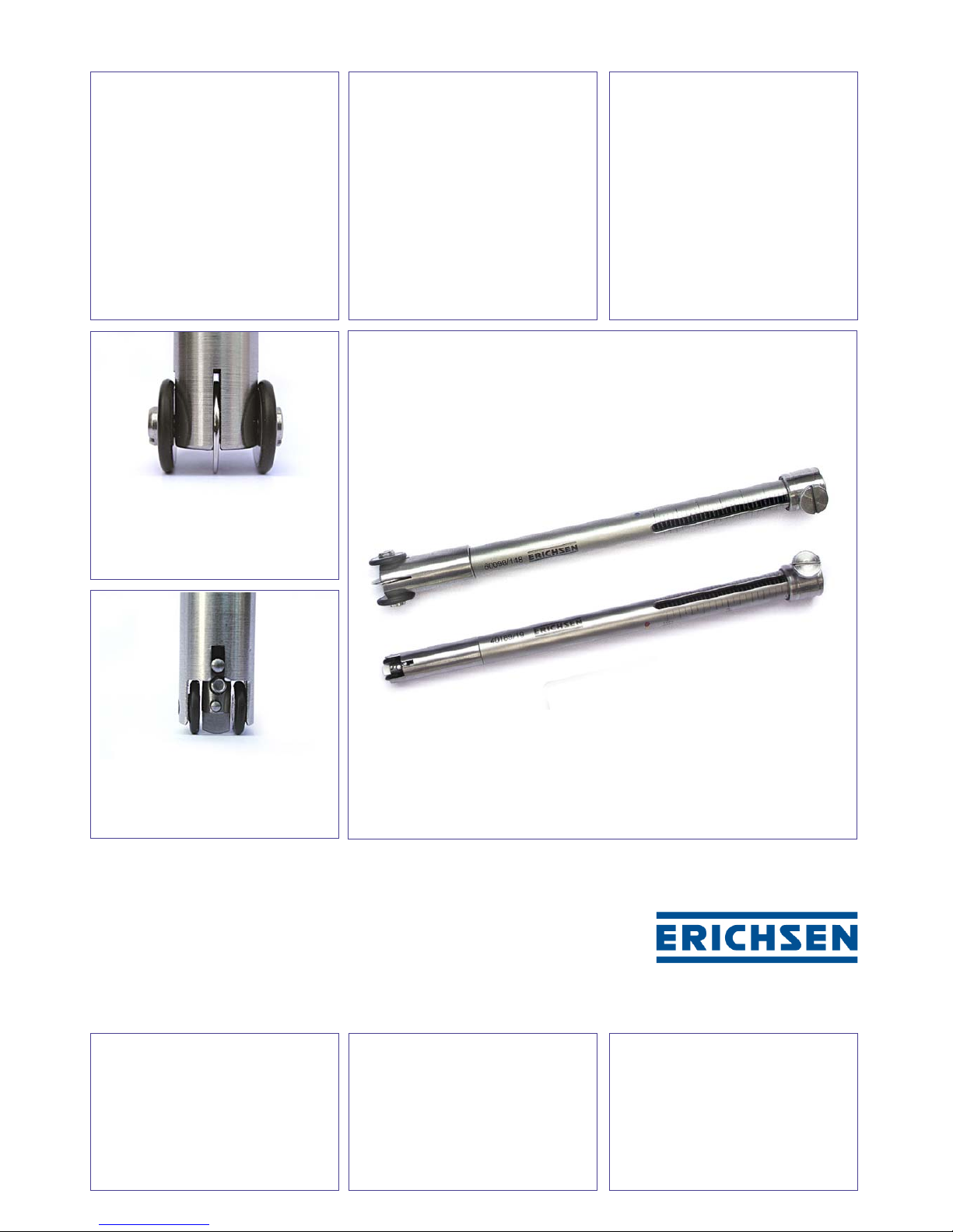
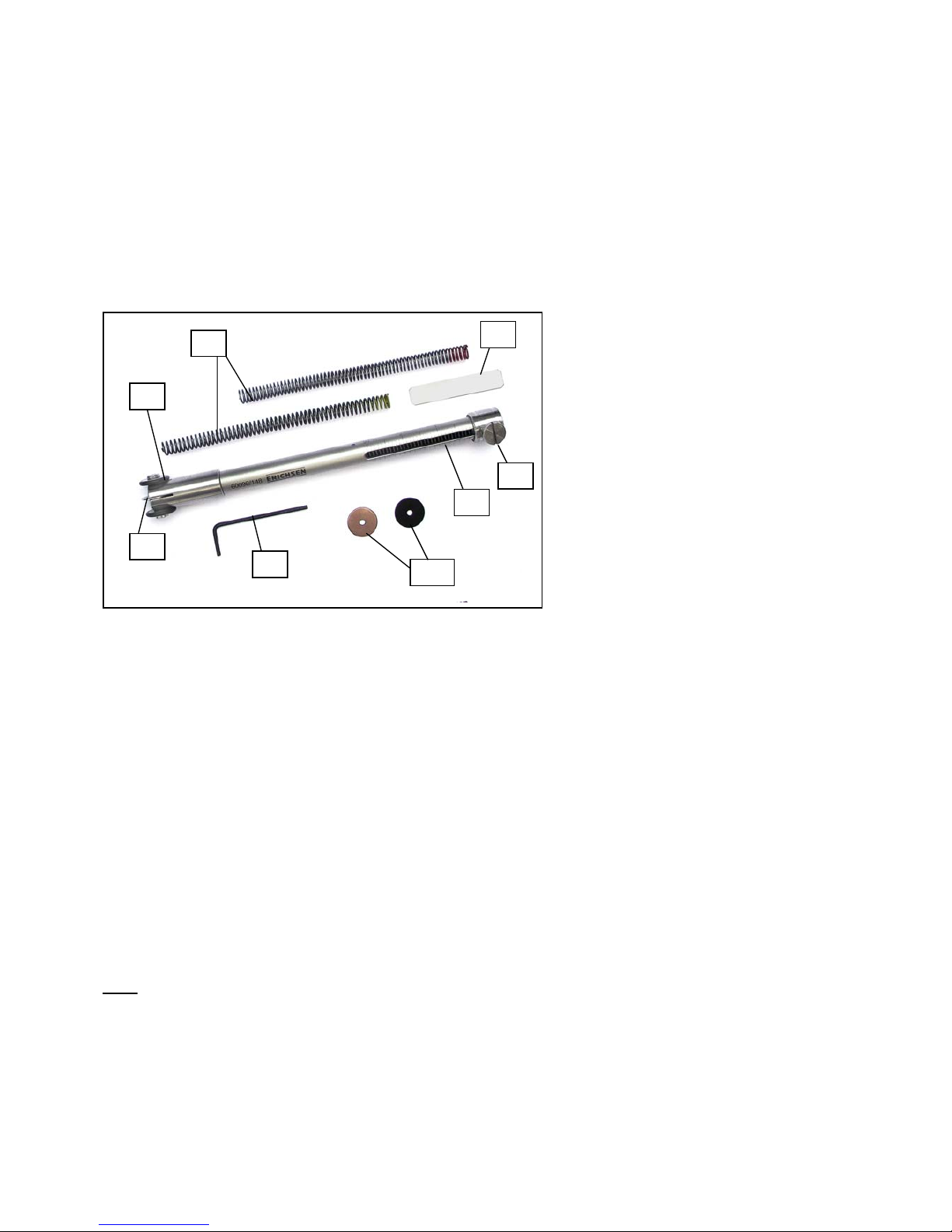
1. Rotating guide rolls
2. Fixed marking disc
3. Test force scale
4. Alternatives test dics
5. Force springs
6. Allen key
7. Locking screw slider
8. Help aid for fixing the locking
screw slider
Design and Function
The scaring tool in the form of a disc, with locking
facility, made of special plastic or metal, is mounted
on a screw and is under pressure from a helical
spring. This applies to a force which is adjustable
from 0 to 20 N. The instrument is placed onto the
surface so that it rests on the two guide wheels and
the marking wheel which is locked in position then
presses onto the surface with the pre-set force from
the spring. The range of spring forces available is
divided into three sections, each covered by one of
three exchangeable springs:
Test range 1: 0 - 3 N - Sensitivity 0,1 N
Test range 2: 0 - 10 N - Sensitivity 0,5 N
Test range 3: 0 - 20 N - Sensitivity 1,0 N.
Note:
The test discs will wear at the point at which they are
used. After 100 tests the discs should therefore be
moved round so as to bring a point about 2 mm
further along on the periphery into operation. The
point at which the marking disc is first used should be
marked by a scratch.
Method of Operation
First set up the selected test wheel depending on the
test required, i. e.
- the plastic disc for scar-resistance tests;
- the copper disc or other special disc for metal
marking.
After tightening the screw it must not be possible to
turn the marking disc. The spring is then set to
provide what is anticipated to be a suitable force and
the instrument is placed perpendicularly onto the test
surface and pressed down so that the guide wheels
touch the surface.
In this way the preset pressure of the test disc is fully
effective on the test surface.
The instrument is then moved a distance of a few cm
so that the wheels roll over the surface, in a rapid
motion appropriate for the scaring effect. The test
result is the spring force in Newton which is just
sufficient to produce a clear surface scar visible with
the naked eye but not a crack or scratch.
If the interest is in the so-called metal marking effect,
the result is expressed in terms of the spring force at
which the surface just shows a black or grey mark.
Page 3

Adhesion and Scratch Resistance Tester, Model 435 S
Purpose and Application
At first developed from the Mar Tester 435, Model
435 S has been adjusted, in cooperation with a well-
known manufacturer of – among others - scaled
indication fittings for vehicle cockpits, especially to
tests of this product group.
When used as an adhesion tester e.g. the coloured
coating applied to the dial of a speedometer in the
shape of raised numbers, points or scale lines, is
tested concerning its adhesion to the substrate, by
lateral slipping with a defined “blunt” test body
geometry, with a preselected test force.
In principle the Model 435 S is feasible for testing the
adhesion of almost all printed scales, numbers,
letters and marks “lying“ on the scale plates’ surface!
When used as a scratch resistance tester for
testing surfaces against “blunt” effects, it is
recommended for testing surfaces on which the
Hardness Test Rod 318 is still too “aggressive” –
even using the largest tip diameter of 1 mm available
for this purpose.
1. Rotating guide rolls
2. Test disc made of steel
3. Test force scale
4. Force springs
5. Allen key
6. Locking screw slider
7. Help aid for fixing the locking srew
slider
Design and Function
The main difference between the Mar Tester 435 and
the new Model 435 S is the direction in which the
test body is moved. While the test body of Model 435
(a disc with locking facility) is moved relatively fast in
longitudinal direction in order to produce a “scar”, the
test direction in which the test body of Model 435 S
is guided, is rotated by 90°.
The part of the test body relevant for the test,
corresponds in its shape exactly to that of Model 435
and is basically, for the time being, only available in
the version made of steel which is most useful within
the scope of products tested up to now.
As the diameter of the test head of Model 435 S is
considerably smaller compared with the steel disc of
Model 435, a central sector of the disc of Model 435
has been chosen as test body for reasons of space
saving. The test body is mounted on a bolt and is
preloaded by an internal helical spring to a force
adjustable from 0 to 20 N. When placing Model 435 S
with the two guide wheel perpendicularly onto the
surface, the rigidly arrested test body acts (with the
preset force) upon the surface. The test force can be
varied – as for Model 435 – by means of 3
exchangeable springs covering three different test
ranges.
Method of Operation
After checking the tight fixing of the test body at the
end of the load transmission bolt, the required force
is adjusted on the scale using the locking screw
slider. Then the Model 435 S is placed
perpendicularly onto the surface to be tested resp.
beside the applied raised coating to be tested, and is
pressed down so that the guide wheels touch the
surface. In this way the preset force acting upon the
test disc is fully effective on the test surface. The
instrument is now moved into the rolling direction the
wheels over the specimen to be tested e.g. against,
for example, scale lines.
The user selects the speed that is adequate for the
product to be tested. When testing e.g. raised
inscriptions, the test result is expressed by the test
force in Newton (N) at which the adhesion of the
coating failed.
For scratch resistance tests of surfaces against
“blunt” effects the test result is the maximum force in
Newton (N) at which the test body does not leave any
trace on the test surface.
Page 4

Order Information
Ord.-No. Product Description
0096.01.31
Mar Tester according to
Oesterle, Model 435
Including
♦ 3 test discs
(duroplast, copper, steel)
♦ 3 force springs
♦ 1 case
Spare Parts
Ord.-No. Product Description
0430.01.32 Duroplast test disc
(per 10 pcs.)
0430.02.32
Test disc made of copper
(per 10 pcs)
0430.03.32
Test disc made of steel
(per 10 pcs.)
Order Information
Ord.-No. Product Description
0268.01.31
Adhesion and Resistance
Tester, Model 435 S
Including:
♦ 1 test disc made of steel
♦ 3 force springs
♦ 1 case
Spare Part
Ord.-No. Product Description
0796.01.32 Test disc made of steel
The right of technical modifications is reserved.
Gr. 14 - TBE/BAE 435/-435 S - IV/2007
 Loading...