

ERICHSEN 243/I, 243 Series, 243/II, 243/II/4, 243/III Technical Description And Operating Instructions
...Page 1
testing equipment for quality management
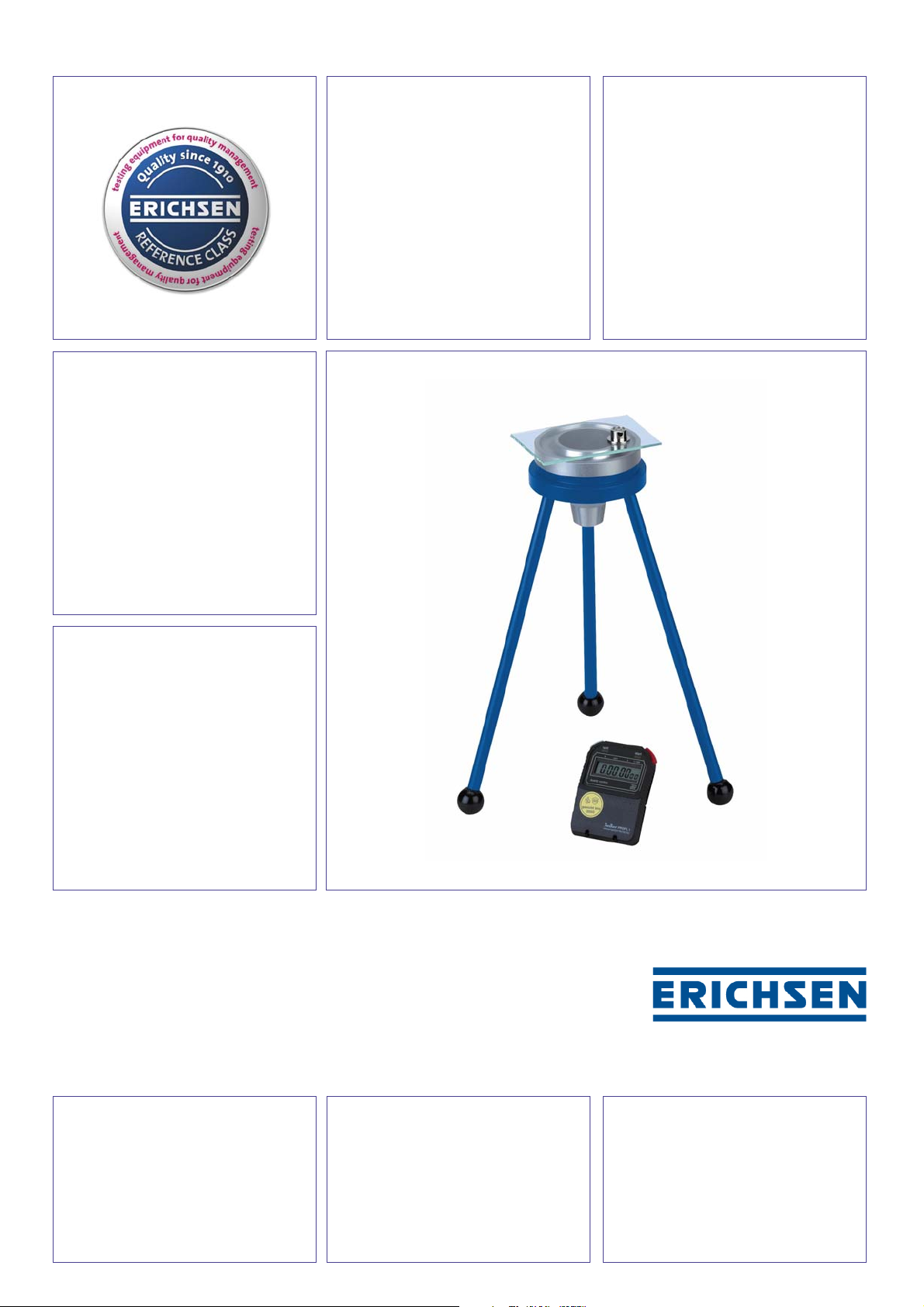
Flowcups
Models 243
A Simple Method
to Measure Viscosity
ASTM D 1200
SNV 37 110
SIS 18 41 15
DIN 53 211
ISO 2431
DIN EN ISO 2431
Technical Description and Operating Instructions
Page 2

VISCOSITY CUPS, Models 243
Purpose and Application
Viscosity Cups remain the most important quick
and simple method to measure the consistency of
fluids in the laboratory and in production.
Viscosity Cups are, however, only suitable for
lower viscosities and not for highly viscous
substances such as pastes, etc.. The most
accurate results are achieved with fluids within
the range complying with Newton’s Law.
Design Details
Viscosity Cups consist of a hollow cylinder which
terminate in a nozzle in the bottom. Excess fluid is
collected in a gutter channel.
In general, the Viscosity Cups are made of
anodised aluminium and the nozzles of stainless
steel. Only the low price model 243/I is made
of Phenol resin (but still with stainless steel
nozzle).
Measuring Principle
The viscosity is established in terms of the time
in seconds in which a precisely controlled volume
of fluid flows out through the nozzle of the
viscosity cup.
Test Procedure
The general test process is described as follows:
♦ Level stand using spirit level
♦ Place cup in the stand or in the temperature
control jacket
♦ Close nozzle
♦ Fill with fluid
♦ Wipe off surplus material across the edge
of the cup with a glass plate, and close cup
with glass plate
♦ Open nozzle
♦ Pull off glass plate horizontally and
simultaneously set stop watch in motion
♦ At the first break off in the fluid flow stop
stop watch and note time
Further details are described in the various
standards. It is to be noted that the Cups are only
calibrated for the specified ranges and for the
specified flow times.
In addition, it is particularly important to follow the
instructions concerning temperatures carefully.
Only a very small difference could lead to
considerable changes and hence wrong
measuring results. Of particular importance is to
understand that it is not sufficient just to make
sure that the fluid is at the right temperature: the
Viscosity Cup must also be at the correct
temperature, if necessary by surrounding it with a
temperature jacket so that the intended
temperature is maintained. It is also essential to
check the temperature of the jet of fluid coming
out of the Cup, since it is at this point that the
actual temperature of the fluid being measured
can be established. Comparable, reproducible
results are only possible if the temperature is kept
fully under control.
Care and Maintenance
After making a measurement the flow cup -
particularly the nozzle - must be carefully cleaned
without, however, using any hard or sharp
implements.
Important:
If remnants of fluid (paint) remain in the nozzle,
the effective size of the nozzle will be altered and
the cup can no longer give accurate measuring
results.
Reference Class:
All versions of Models 243/III and 243/VII as well
as Model 243/II with nozzle dia. 4 mm are
supplied with a Manufacturer’s Certificate M
accordance with DIN 55 350-18 that includes
among others the following information:
Flow time with percentage deviation from setting
value, type of calibration oil, product identification,
test equipments used with calibration status, date,
name of inspector.
In the medium range of application the flow time is
determined by means of a retraceably calibrated
test oil. The maximum deviation from the setting
value should not exceed 3 %.
in
Page 3

VISCOSITY CUPS, Models 243
MODEL No.
(Material)
243/I
(Phenol resin)
243/II
(Alu anodised)
243/II/4
(Alu anodised)
243/III
(Alu anodised)
243/VII
(Alu anodised)
STANDARD
technically
equivalent to
DIN 53 211
technically
equivalent
DIN 53 211
DIN 53 211
SNV 37 110
SIS 184 115
ASTM D 1200
ISO 2431
EN ISO 2431
*
NOZZLE
dia/No.
2 mm
3 mm
4 mm
6 mm
8 mm
2 mm
3 mm
6 mm
8 mm
4 mm
Nr. 2
(2.5 mm)
Nr. 3
(3.4 mm)
Nr. 4
(4.1 mm)
Nr. 5
(5.2 mm)
3 mm
4 mm
5 mm
6 mm
MEASURING RANGE
22 - 55 mm²/s
45 - 300 mm²/s
90 - 682 mm²/s
300 - 1200 mm²/s
500 - 2000 mm²/s
22 - 55 mm²/s
45 - 300 mm²/s
300 - 1200 mm²/s
500 - 2000 mm²/s
90 - 682 mm²/s
32 - 118 mm²/s
31 - 215 mm²/s
59 - 367 mm²/s
217 - 1185 mm²/s
8 - 42 mm²/s
34 - 135 mm²/s
91 - 325 mm²/s
188 - 684 mm²/s
* The ASTM D 1200 Standard stipulates a maximum allowed flow time tolerance of ± 10%.
Each model 243/III is always manufactured within a maximum flow time tolerance of ± 6.5%!
Accessories
Stand
Three legged stand suitable for all flow cups
listed, with spirit level.
Temperature Control Jacket
Available for Models 243/II, 243/III and 243/VII.
Thermometer
To DIN 12 755,
Scale 0 - 50°C, read off accuracy 0.2°C.
Digital Stop Watch
with calibration certificate; LCD, indication range:
9 hours, 59 minutes, 59,99 seconds;
height of digits: 8 mm, two-button operation.
CUPTIMER 243-T
Opto-electronic measuring instrument for the
exact determination of the flow time using standardised flow cups.
Viscosity Nomogram, Model 458
To read off the various viscosity scales such as,,
for example DIN, Ford, ISO, etc., in absolute
viscosity values, and also for temperature
correction for the measured value.
ViscoSoft ® 460 -FC
Software for rapid conversion between viscosity
and efflux time to be used with standardized flow
cups.
Page 4

VISCOSITY CUPS, Models 243
Ordering Information
Product Name Nozzle Dia. Order No. Remarks
Model 243/I 2 mm 0024.01.31 of Phenol resin,
Model 243/I 3 mm 0024.05.31 Manufacturer’s Test
Model 243/I 4 mm 0024.02.31 Certificate M
Model 243/I 6 mm 0024.03.31 upon request
Model 243/I 8 mm 0024.04.31
Model 243/II 2 mm 0064.01.31 of Anodised Aluminium,
Model 243/II 3 mm 0064.05.31 Manufacturer’s Test
Model 243/II 6 mm 0064.03.31 Certificate M
Model 243/II 8 mm 0064.04.31 upon request
Model 243/II 4 mm 0064.02.31 of Anodised Aluminium with
Manufacturer’s Test Certificate M
ditto 0249.01.32 with official Test Certificate issued by DKD
Temperature jacket 0483.01.32 for Model 243/II
Model 243/III No. 2 0060.01.31
Model 243/III No. 3 0060.01.31 with Manufacturer’s Test Certificate M
Model 243/III No. 4 0060.03.31
Model 243/III
Temperature jacket 0483.02.32 for Model 243/III
Model 243/VII 3 mm 0061.01.31
Model 243/VII 4 mm 0061.02.31 of Anodised Aluminium,
Model 243/VII 5 mm 0061.04.31 with Manufacturer’s Test Certificate M
Model 243/VII 6 mm 0061.03.31
Model 243/VII 3 mm 0250.01.32
Model 243/VII 4 mm 0250.02.32 with official Test Certificate issued by DKD
Model 243/VII 5 mm 0250.09.32
Model 243/VII 6 mm 0250.03.32
Temperature jacket 0483.03.32 for Modell 243/VII
Stand with spirit level 0478.01.32
Thermometer 570911341
Digital Stop Watch 560911241 with calibration certificate
Spare Glass plate 610911941
No. 5 0060.04.31
For information on our DIP FLOW CUPS we refer to our Brochure No. 321/322/343.
The right of technical modifications is reserved.
Group 2 - TBE 243 – VIII/2007
 Loading...