

ERHARD ROCO Series, ROCO 5065 Series, ROCO 5064 Series, ROCO 5061 Series Operating Instructions Manual
BA50E103
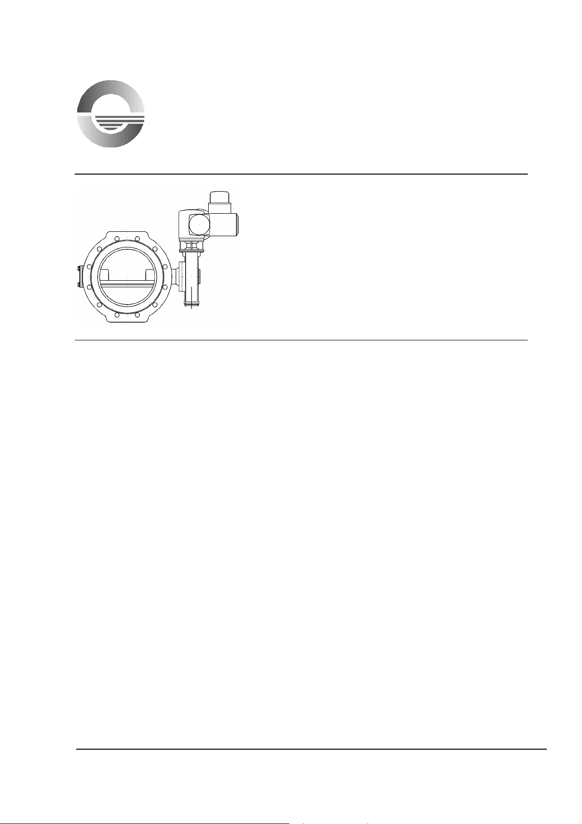
Operating Instructions
ROCO Butterfly Valve
with SKG Slider-crank Mechanism,
with Electric Multi-turn Actuator
These operating instructions must always be used in combination with operating
instructions BA01E001!
1 Product and Performance Description
1.1 Product Description
ROCO Butterfly Valve to DIN 3354, part 2
with flanges, double-offset shaft bearing, resilient-seated, tightly closing, of ductile cast
iron.
Operation by SKG slider-crank mechanism by means of handwheel, extension stem,
underground installation set, chain wheel, electric multi-turn actuator.
Nominal sizes: DN 150, 200, 250, 300, 350, 400, 450, 500, 600
Pressure ratings: PN 10, 16
Prod. No.: 5064 .... PN 10
5065 .... PN 16
5061 .... PN 16/GN 10
1.2 Performance Description (see fig. 1)
A valve disc (3) hinged in the body (1) is moved through an actuating shaft (7) which
protrudes into a laterally mounted part-turn gearbox. The pipeline is isolated, when the
valve disc is vertical to the flow direction. Tight closure on the seat in the body is achieved
by a sealing element (profile sealing ring). The travel between ”OPEN” and ”CLOSED”
position (90° swinging movement) is limited by means of stop nuts on the actuating stem of
the attached part-turn gearbox. Normally, the valve closes in clockwise direction (turning
the handwheel to the right).
1 Product and Performance Description
2 Design Features of ROCO Butterfly Valve
3 Installation in the Pipeline
4 Initial Operation
5 Operation and Application
6 Maintenance
7 SKG Slider-crank Mechanism
8 Electric Multi-turn Actuator
BA50E103
Issue 02-06
REV2
ERHARD-Armaturen x D-89502 Heidenheim x Postfach 1280
Phone +49 (0)7321 320-0 +49 (0)7321 320-525
e-mail: info@erhard.d e Internet: http://www.erhard.de
Page 1/13

Operating Instructions for ROCO Butterfly Valve
____________________________________________________________________
2 Design Features
Figure 1: Sectional Drawing of ROCO Butterfly Valve
Part Description Spare
part
1 Body 12 O-ring
2 Bearing bush 13 Hexagon screw
3 Valve disc 14 Washer
4 Profile sealing ring X 15 Key
5 Countersunk screw 16 Tab washer
6 Threaded pin 17 Hexagon screw
7 Actuating shaft 18 Shaft sealing set,
8 Trunnion O-rings, back-up rings
9 Bearing ring, divided 19 Retaining ring
10 Threaded pin 20 Cylindrical screw
11 Bearing cover 21 Parallel key
Part Description Spare
part
X
consisting of: spacer,
• Main sealing ring: steel-reinforced profile sealing ring (4) internally and externally rubbercoated, optimum corrosion protection, easily replaceable and adjustable.
• Body seat: enamel coated seat (product No. 50.. 72..) or rolled-in solid seat ring of
stainless steel (product No. 50.. 95..).
• Connection key/valve disc: well-approved and robust key connection (15) for force
transmission without clearance, tab washer (16).
• Gearbox connection: to prEN 12116 (DIN ISO 5211), round spigot with parallel key.
BA50E103
Issue 02/06
REV 2
ERHARD-Armaturen x D-89502 Heidenheim x Postfach 1280
Phone +49 (0)7321 320-0 +49 (0)7321 320-525
e-mail: info@erhard.d e Internet: http://www.erhard.de
Page 2/13

Operating Instructions for ROCO Butterfly Valve
____________________________________________________________________
• Shaft sealing: on the drive side by means of fully enclosed 0-rings (18) of stainless
material, on the bearing side by O-ring (12) enclosed in the bearing cover (11).
• When the gearbox is disassembled, the shafts (7) and shaft sealing (18) are protected
against blowing-off.
• Shaft bearing: maintenance-free and self-lubricating plain bearings (2).
3 Installation into the Pipeline
Remove all packing material from the valve. Prior to installation, check the pipeline for
impurities and foreign bodies and clean it if necessary.
Attention !
It is important that all around the valve there is free access for operation and
maintenance. For outdoor installation, the customer has to protect the valve against
direct effects of the weather.
During installation of the valve, the distance between the pipe flanges should exceed the
valve face-to-face dimension by at least 20 mm. Thus, the raised faces will not be
damaged and the gaskets can be inserted. Steel-reinforced rubber seals are
recommended to be used as flange gaskets (consider resistance to flow medium and
temperature), for slip-on flanges they are absolutely necessary.
The mating pipe flanges must be plain-parallel and concentric.
Tighten the connecting bolts evenly (without distortion) and crosswise. The pipeline
mustn’t by any means be pulled up to the valve.
ROCO Butterfly Valves can be installed in any position.
In open position the valve disc exceeds the valve face-to-face dimension.
Keep corresponding distance to any fitting or valve, e.g. check valve.
4 Initial Operation
After installation, check valve for smooth operation: move the valve over the total travel
(Open – Closed) by means of operating element.
5 Operation and Application
5.1 Admissible Operation
The valve disc is designed for flow from the direct side (A preferred flow direction) as well
as from the indirect side (B).
The valve is operated by means of the handwheel, chain wheel or operating key to
DIN 3223. It is not permissible to apply excessive forces.
Max. admissible flow velocities:
PN 10: 4 m/sec.
PN 16: 5 m/sec.
BA50E103
Issue 02/06
REV 2
ERHARD-Armaturen x D-89502 Heidenheim x Postfach 1280
Phone +49 (0)7321 320-0 +49 (0)7321 320-525
e-mail: info@erhard.d e Internet: http://www.erhard.de
Page 3/13

Operating Instructions for ROCO Butterfly Valve
____________________________________________________________________
5.2 Inadmissible Operation
Installation behind elbows or similar disturbing installation parts is to be prevented.
Long-time operation in throttled position leads to higher wear. When the valve is used as
throttling valve, it has to be checked whether the valve is suitable for the operating
conditions.
Do not exceed limiting values of the flow medium temperature.
Do not exceed limiting values of the working pressure.
Closed valve may only be charged up to the nominal pressure.
For EPDM profile sealing rings and sealings: rubber parts must not get in contact with oil
or grease (EPDM swells!).
6 Maintenance
6.1 Maintenance and Inspection
ROCO Butterfly Valves are equipped with maintenance-free plain bearings. Gearbox stem
and gearbox bearing are of the long-time lubricating type. Control of the performance and
tightness is to be done regularly in intervals of <= 4 years according to DVGW print
W390.
Before carrying out work on the valve, the repair valve must be
closed and the pipe section must be made pressureless.
Check external condition of the valve including operating gear.
If necessary clean the valve and repair the coating.
Check tightness at the flanges.
Check well-running of valve and operating gear.
Move valve manually over total travel.
Check seat tightness: close the valve.
Check pressure drop upstream and downstream of the valve.
6.2 Readjustment and Repair
6.2.1 Readjustment of the Profile Ring, fig. 2.
ROCO Butterfly Valves are equipped with a readjustable sealing system. The profile
ring (4) can be readjusted in closed position of the valve disc. For this purpose, loosen
the threaded pins (6) and tighten evenly the countersunk screws (5) in a crosswise
manner. As the profile sealing ring acts very fast when tightening, we recommend to
proceed by taking small steps (half turn of the screws). Afterwards tighten threaded
pins (6) by turning them in clockwise direction and thus locking the profile sealing ring.
BA50E103
Issue 02/06
REV 2
ERHARD-Armaturen x D-89502 Heidenheim x Postfach 1280
Phone +49 (0)7321 320-0 +49 (0)7321 320-525
e-mail: info@erhard.d e Internet: http://www.erhard.de
Page 4/13

Operating Instructions for ROCO Butterfly Valve
____________________________________________________________________
Fig. 2: Sealing Zone of ROCO Butterfly Valve
6.2.2 Replacement of the Profile Sealing Ring, fig. 2.
• Turn valve disc off the ”CLOSED” position of the body seat by approx. 20°
to 30°.
• Loosen and screw off countersunk screws (5).
• Remove profile sealing ring (4) by means of lever force.
• Clean profile groove in valve disc and repair corrosion protection if necessary.
• Introduce new profile ring by turning it. It must be fully inserted into the disc.
When the profile ring is correctly mounted, it can be moved easily in the disc.
Note: The profile sealing ring can be inserted more easily, when it is slightly
wetted or greased prior to mounting (please use a grease suitable for potable
water).
Profile sealing rings of EPDM must not get in contact with grease!
• Screw-in countersunk screws (5) and tighten crosswise by means of tightening
torque according to table 1.
• Afterwards screw-in threaded pins (6) and tighten them.
Note: When mounting the countersunk screws and threaded pins, we
recommend to use commercial screw locking and sealing materials thus
achieving an improved corrosion protection and increased safety against
slackening.
BA50E103
Issue 02/06
REV 2
ERHARD-Armaturen x D-89502 Heidenheim x Postfach 1280
Phone +49 (0)7321 320-0 +49 (0)7321 320-525
e-mail: info@erhard.d e Internet: http://www.erhard.de
Page 5/13

Operating Instructions for ROCO Butterfly Valve
____________________________________________________________________
M
[Nm]
A
10 bars 16 bars
DN 150 5 6
DN 200 5 6
DN 250 10 12
DN 300 12 13
DN 350 13 14
DN 400 13 14
DN 450 14 17
DN 500 14 17
DN 600 17 23
Table 1: Tightening Torques M
for Clamping Ring Screws
A
6.2.3 Replacement of Shaft Sealing, fig. 3.
Required spare parts: shaft sealing set consisting of:
• Spacer (22); 1 piece
• External O-rings (23); 2 pieces
• Internal O-ring (24); 2 pieces
• Back-up rings (25); 3 pieces
• O-ring for bearing cover (12); 1 piece
Fig. 3: Shaft Sealing Zone of ROCO Butterfly Valve
Drive Side:
• Dismount gearbox/part-turn actuator from Butterfly Valve (see chapter 7).
• Remove parallel key (21).
• Unscrew cylindrical screws (20) and remove retaining ring (19).
• Remove external O-ring (23) and back-up ring (25) as far as possible.
• Place two medium-sized slotted screw drivers one opposite the other at the
BA50E103
Issue 02/06
REV 2
spacer (22) and remove spacer by lever force (spacer will be damaged during
this procedure).
ERHARD-Armaturen x D-89502 Heidenheim x Postfach 1280
Phone +49 (0)7321 320-0 +49 (0)7321 320-525
e-mail: info@erhard.d e Internet: http://www.erhard.de
Page 6/13

Operating Instructions for ROCO Butterfly Valve
____________________________________________________________________
• Remove remaining sealing parts.
• Clean space of installation.
• Slightly grease 0-ring (23), insert into groove on the backside of the new 0-ring
(22) and press spacer with 0-ring into the installation space until reaching the
stop.
• Insert the second O-ring into the groove between body and spacer.
• Assemble shaft sealing system one after the other as follows:
Back-up ring/O-ring/back-up ring/O-ring/back-up ring (24, 25) taking care that the
O-rings at the parallel key groove of the shaft will not be damaged.
• Mount retaining ring (19) with cylindrical screw (20).
• Mount gearbox/part-turn actuator (see chapter 7).
Bearing Side:
• Dismount bearing cover (11) by unscrewing the hexagon screws (13).
• Remove old O-ring (12) from the groove of the bearing cover.
• Clean O-ring groove.
• Insert new O-ring (12) and remount bearing cover (11) . During mounting see to it
that the O-ring is retained in the groove and is not jammed between body and
bearing cover.
7 SKG Slider-crank Mechanism
7.1 Design Features
• Design (Figure 4): Attachable quarter-turn gearbox according to the slider-crank
principle. The rotation of the stem (2) is changed into a swinging movement of the
gearbox crank by means of the stem nut (5) and the gearbox bracket (8) (articulated
lever). The gearbox crank is rigidly connected to the valve shaft by means of the
output shaft. The slider-crank mechanism is irreversible.
• Cast iron encapsulated gearbox case totally enclosed (enclosure rating IP 68).
• Interfaces:
− Output: to prEN 12116 (DIN ISO 5211), round spigot with parallel key.
− Input: flanged bearing with round trunnion for receiving the handwheel, chain
wheel, extension stem or underground installation set or flange to DIN 5210, shape
B1 (plug socket) for connecting an electric multi-turn actuator.
• Limit stops: Solid stop nut (6) on the stem (2). ”CLOSED” position is adjustable.
Exceeding load will be absorbed by the stem and does not affect the case
components of the gearbox. Maximum input torque: 450 Nm (in the limit positions).
• Position indicator: The indicator which is directly connected to the valve shaft is
visible through a sight glass on the gearbox case. The sight glass is made of impact
resistant polycarbonate (PC) and thus suitable for plant, pit, and underground
installation.
BA50E103
Issue 02/06
REV 2
ERHARD-Armaturen x D-89502 Heidenheim x Postfach 1280
Phone +49 (0)7321 320-0 +49 (0)7321 320-525
e-mail: info@erhard.d e Internet: http://www.erhard.de
Page 7/13

Operating Instructions for ROCO Butterfly Valve
____________________________________________________________________
Mechanism design for mounting Mechanism design for handwheel,
multi-turn electric actuator buried installation, stem extension
Figure 4: Sectional Drawing of Slider-crank Mechanism SKG
Part Description Spare part Part Description Spare part
1 Gearbox casing 16 Indicator
2 Stem 17 Cover
3 Bearing ring 18 Gasket
4 Axial bearing 19 Cylindrical screw
5 Stem nut 20 Sight glass
6 Stop nut 21 Flanged bearing1)
7 Retention pin 22 Neck bearing2)
8 Bracket 23 Bush
9 Gearbox crank 24 O-ring1)
10 Bush 25 Hexagon screw
11 Rivet pin 26 Washer
12 Output shaft 27 Parallel key
13 Threaded pin 28 Follower bush2)
14 Bush 29 Close-tolerance grooved
pin
2)
15 Bush 30 Parallel key2)
1)
Parts only applicable for design with handwheel, for underground installation and extension stem
2)
Parts only applicable for design for/with electric multi-turn actuator
BA50E103
Issue 02/06
REV 2
ERHARD-Armaturen x D-89502 Heidenheim x Postfach 1280
Phone +49 (0)7321 320-0 +49 (0)7321 320-525
e-mail: info@erhard.d e Internet: http://www.erhard.de
Page 8/13

Operating Instructions for ROCO Butterfly Valve
____________________________________________________________________
7.2 Operation and Application
SKG slider-crank gearboxes are used for operating valves with an operating travel
(part-turn movement) of up to 90°.
Manual operation by means of handwheel, chain wheel, underground installation set,
operating key.
Motor operation by means of electric part-turn and modulating actuators.
SKG gearboxes are suitable for plants and pit installation as well as buried and
under-water installation up to a max. flooding height of 6 m water column.
7.3 Mounting
Attention:
Prior to mounting the SKG gearbox to the valve, ensure that both parts are in the
same limit position OPEN or CLOSED.
• Plug output shaft (12) onto the valve shaft up to the flange (see fig. 5) and lock by
threaded pin (13).
• Screw indicator (16) into the centering of the valve shaft and align it parallelly to
the valve disc.
• Grease the toothing of the output shaft (12).
• Plug the gearbox and draw the fastening screws crosswise with torque according
to table 2.
Mt [Nm]
M10 48
M12 85
M16 210
M20 410
Tightening Torques for Fastening
Screws of Gearbox
Fig. 5: Mounting of Output Shaft
Table 2:
BA50E103
Issue 02/06
REV 2
ERHARD-Armaturen x D-89502 Heidenheim x Postfach 1280
Phone +49 (0)7321 320-0 +49 (0)7321 320-525
e-mail: info@erhard.d e Internet: http://www.erhard.de
Page 9/13

Operating Instructions for ROCO Butterfly Valve
____________________________________________________________________
7.4 Setting the Limit Stop (”CLOSED” position) (fig. 4)
• Remove cover (17) and gasket (18) by loosening the cylindrical screws (19).
• Raise the retention pin (7) of the stem nut (6) by means of a slotted
screwdriver pressing the screwdriver into the groove provided for this
purpose between stop nut and annular spring.
• The stop nut can be positioned by turning the screwdriver.
• Having reached the position of the stop nut, draw off the screwdriver. Then
slightly carry on turning the stop nut until the retention pin is perceptibly
caught.
• Check swinging angle by opening and closing the valve.
• Mount cover (17)
7.5 Maintenance
Stem (2) and axial bearing (4) have a long-time lubrication. The performance
of the valve should be checked regularly at least every four years according
to DVGW print W 390.
Regreasing the Trim of the Stem Gearbox:
• Move valve into ”OPEN” position.
• Unscrew hexagon screws (25) for fixing the neck bearing/flanged bearing (21/22)
and remove them.
• Screw-out stem (2) by turning to the right until reaching stop nut.
• Lift off bearing ring (3) so that the whole stem will be accessible.
• Unscrew cover (17) by turning off the cylindrical screws (19).
• Grease stem, axial bearing and sliding ways of stem nut.
• Mount gearbox vice versa and operate it several times.
Lubricating agent Manufacturer Standard
ALVINA Fett R3 (grease) SHELL DIN 51502 K-L3n
TEXANDO FO20 TEXACO DIN 51825 K-2n
Table 3: Recommended Lubricating Agents
BA50E103
Issue 02/06
REV 2
ERHARD-Armaturen x D-89502 Heidenheim x Postfach 1280
Phone +49 (0)7321 320-0 +49 (0)7321 320-525
e-mail: info@erhard.d e Internet: http://www.erhard.de
Page 10/13

Operating Instructions for ROCO Butterfly Valve
____________________________________________________________________
8 Electric Multi-Turn Actuator
The electric actuator is mounted on the neck bearing of the stem gearbox. The standard
type is equipped with:
• Torque and travel switches with 1 make and 1 break contact each
• Blinker transmitter for indication of motor operation
• Thermal switch in the motor winding
The valve is switched off in the following manner:
in closing direction travel dependent
in opening direction travel dependent
The switching points of the travel and torque switches are set at the factory. Moreover,
the torque switches serve as safety switches, e.g. in intermediate positions.
When the valve is supplied without mounted electric actuator, the travel switches have to
be adjusted after mounting the electric actuator.
See paragraph "Initial Operation: Resetting the Limit Switches" (8.2).
Observe the relevant safety measures (VDE/TAB, etc.) and the instructions of the
manufacturer of the electric actuator concerning transport, storage, initial
operation and maintenance.
For the electrical connection, observe the suggested wiring and terminal diagram
supplied by the manufacturer of the electric actuator (travel, torque and thermal
switches, motor, and heating device in case).
Measure the insulating resistance of the motor prior to connection. (If it is less than
500 K-ohms, this shows that there is moisture in the winding. Remove the motor for
drying-up and heat it by means of a hot-air fan or in a heating chamber: max. admissible
temperature 100 °C).
Compare the existing voltages with the data on the nameplate. After connection, the
covers and the cable glands on the electric actuator have to be closed and sealed
carefully.
BA50E103
Issue 02/06
REV 2
ERHARD-Armaturen x D-89502 Heidenheim x Postfach 1280
Phone +49 (0)7321 320-0 +49 (0)7321 320-525
e-mail: info@erhard.d e Internet: http://www.erhard.de
Page 11/13

Operating Instructions for ROCO Butterfly Valve
____________________________________________________________________
8.1 Jogging Operation and Manual Emergency Operation
A t t e n t i o n :
If a foreign body is jammed in when closing the valve, the corresponding torque switch
responds and switches off the motor. The time lag between response of the torque
switch and disconnection of the motor from the network depends on the signal delay. If a
new closing order is given before the valve has been opened sufficiently, the torque will
increase. If this procedure is repeated several times, the torque will accumulate. The
valve and its operating elements are not designed for such an emergency.
We explicitly draw your attention to the fact that such jogging operation is inadmissible.
Jogging is only admissible under the following conditions:
If the torque switch responds in intermediate position, the valve must first be moved in
the opposite direction until the torque switch completely returns to its original position.
Only now the valve may be moved again in the direction in which the disturbance
occurred. Proceeding this way, you will obtain torques corresponding to the torques set
at the torque switch. Moreover, the foreign matter can come off and be flushed out of the
seating zone.
Operation by Emergency Handwheel:
If the valve is operated by means of the handwheel of the electric actuator, the torque
switches do not provide any safety function.
If a foreign body is jammed with the valve being in intermediate position, excessive
operating force – particularly in case of high gear reduction – might be damaging to the
actuating components. Therefore:
If any resistance is detected during emergency handwheel operation, some turns must
be made in the opposite direction before the valve is moved in the direction in which the
disturbance occurred (flush out the foreign body). Continue operation with utmost care,
in no case using excessive force. If need be, repeat flushing operation.
8.2 Initial Operation:
1. Turn the valve manually to central position.
2. Check movement of the indicator at the stem gearbox and thus the direction of
rotation of the actuator by brief electrical starting.
3. In case of faulty direction of rotation, change the poles of the motor connection.
4. Check once again the direction of rotation shown by the indicator by means of brief
electrical starting.
5. Check disconnection of the torque and travel switches in OPEN and CLOSED
directions by operating the switches manually in central position.
BA50E103
Issue 02/06
REV 2
ERHARD-Armaturen x D-89502 Heidenheim x Postfach 1280
Phone +49 (0)7321 320-0 +49 (0)7321 320-525
e-mail: info@erhard.d e Internet: http://www.erhard.de
Page 12/13

Operating Instructions for ROCO Butterfly Valve
____________________________________________________________________
6. Change poles if necessary.
7. Carry out complete travel only when the correct direction of rotation and
disconnecting performance are ensured.
In case of faulty direction of rotation, the travel and torque switches do not work.
Resetting the Limit Switches:
1. Move the valve manually against the limit stop in indicator position ”C”.
2. Return by one turn of the stem.
3. Adjust ”OPEN” travel switch according to the operating instructions for the electric
actuator.
4. Move the valve manually against the limit stop in indicator position ”B”.
5. Return by one turn of the stem.
6. Adjust the ”CLOSED" travel switch according to the operating instructions for the
electric actuator.
If the proposed measures are not respected, we are not prepared to be made
liable for probably occurring damages.
BA50E103
Issue 02/06
REV 2
ERHARD-Armaturen x D-89502 Heidenheim x Postfach 1280
Phone +49 (0)7321 320-0 +49 (0)7321 320-525
e-mail: info@erhard.d e Internet: http://www.erhard.de
Page 13/13
 Loading...