

Page 1
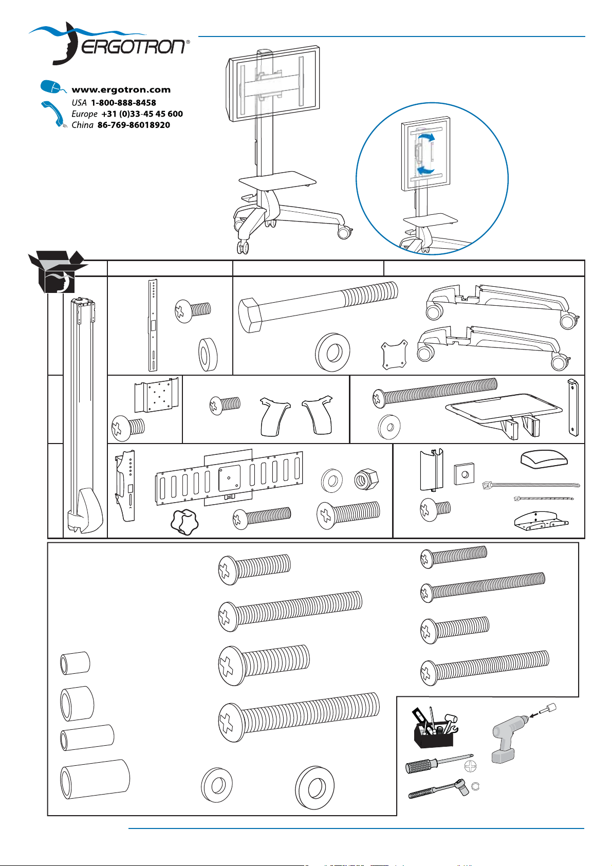
Neo-Flex Mobile Media Center, VHD & UHD
with 90˚ Portrait/Landscape rotation
User's Guide
Guía del usuario
Manuel de l’utilisateur
90˚
AB C D
1x
1
1x
2
3
Attach Display
ATORNILLE MONITOR
FIXER L’ECRAN
4x
4x
SHORT SPACER A
4x
SHORT SPACER B
4x
LONG SPACER A
2x
M6x8mm
2x
M5 x 10mm
1x
4x
4x
8x
1x
4x
M3.5 x 6mm
2x
4x
M6x20mm
4x
M6x45mm
4x
4x
M10 x 60mm
1x 1x
M4 x 16mm
M8x25mm
M8x50mm
4x
1x
4x
8x
4x2x
4x
M6x14mm
1x
1x
M3 x 37mm
4x
1x
M5x8mm
4x
4x
4x
4x
1x
1x
M4x20mm
M4x40mm
M5x20mm
M5x40mm
2x
1x
2x
2x
1x
14mm
888-24-064-M-00 rev. B • 12/08
4x
LONG SPACER B
8x
WASHER A
4x
WASHER B
15mm
1/14
Page 2
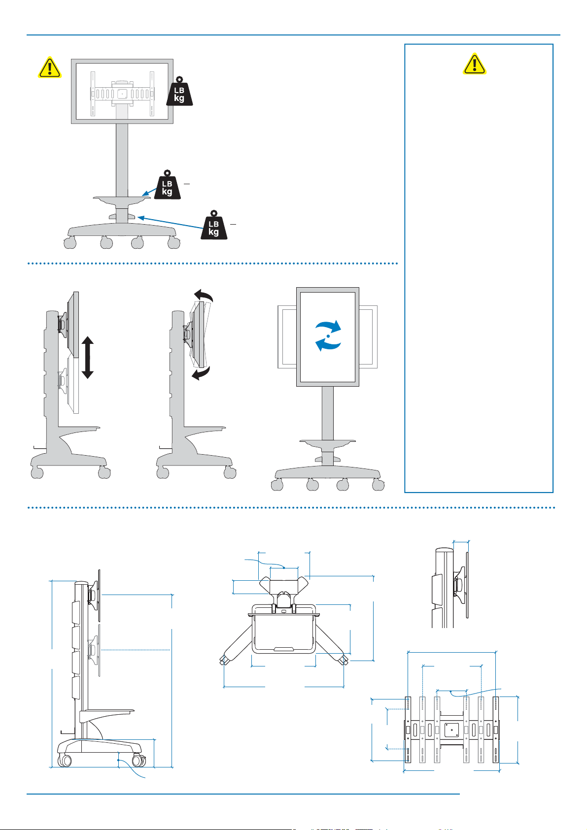
20"
(510 mm)
VHD: 50 - 90 lbs
(22.7 - 40.8 kg)
UHD: 90 - 120 lbs
(41 - 54 kg)
<30 lbs
(15 kg)
<5 lbs
(2.2 kg)
-15˚
+5˚
90˚
Stored Energy Hazard: The lift mechanism
WARNING
in the tower is under tension and will move
up rapidly, on its own, as soon as attached
equipment is removed. For this reason,
DO NOT remove equipment or make
adjustments to lift tension unless the front
assembly has been moved to the highest
position on the tower! Failure to follow this
instruction may result in serious personal
injury and/or equipment damage!
ADVERTENCIA
Riesgo de energía almacenada: El
mecanismo de elevación de la torre está
bajo tensión y se moverá rápidamente hacia
arriba por sí solo si se retira el equipamiento
que hay conectado al mismo. Es por ello
que NO deberá quitar equipamiento ni
hacer ajustes en la tensión de elevación a
menos que la estructura delantera se haya
movido antes hacia la posición más alta de
la torre. No seguir estas instrucciones podría
provocar daños personales y/o materiales
graves.
AVERTISSEMENT
Danger : Le mécanisme d’élévation dans la
tour est sous tension et se lève rapidement,
tout seul, dès que le matériel est retiré. Pour
cette raison, NE PAS retirer votre matériel
ou faire des ajustemensts à la tension
d’élévation à moins que la partie avant
n’ait été mise à la position la plus élevée de
la tour ! Risque de blessure corporelle ou
d’endommagement matériel en cas de non
respect de cette instruction.
64"
(1633 mm)
2/14
38.4"-58.4"
(974 - 1484 mm)
9.8"
(249 mm)
5"
(127 mm)
9.8"
(250 mm)
4.9"
(124 mm)
16.8"
(427 mm)
22"
(559 mm)
42"
(1067 mm)
(746 mm)
17"
(432 mm)
15.7”
(400 mm)
29.4"
(200 mm)
7.87”
3.69”
(93.7 mm)
23.6” (600 mm)
15.7”
(400 mm)
7.87” (200 mm)
17.7”
(450 mm)
24.6”
(625 mm)
888-24-064-M-00 rev. B • 12/08
Page 3
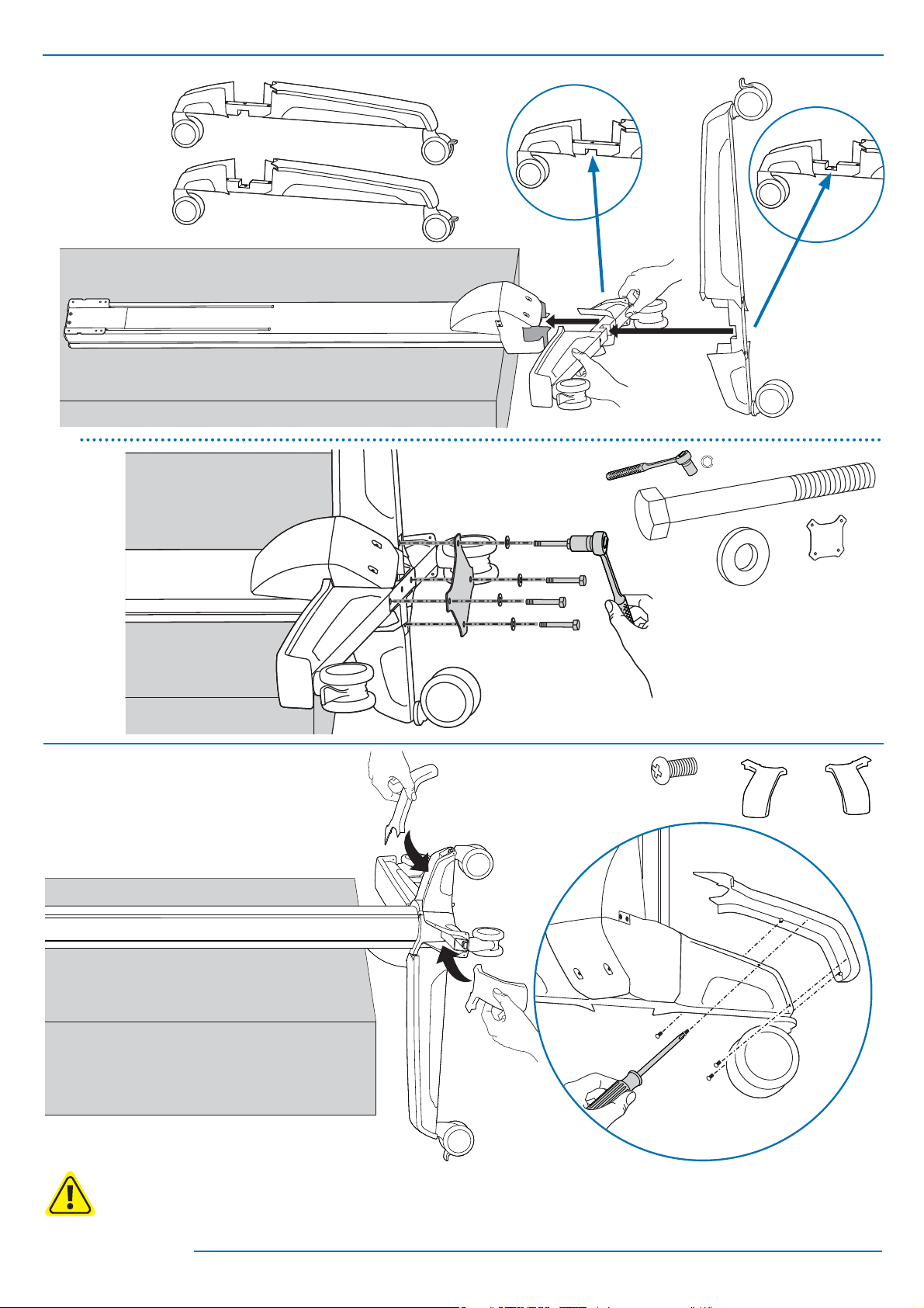
1
1x
a
1x
15mm
b
4x
1x
4x
2
CAUTION: DO NOT overtighten fasteners. Overtightening may cause damage to your equipment.
Cuidado:: No sobreapriete los tornilllos, pues podría causar un daño al equipo.
Attention: ne forcez pas le serrage de la vis, cela pourrait endommager l’écran et/ou les attaches.
8x
M3.5 x 6mm
1x
1x
888-24-064-M-00 rev. B • 12/08
3/14
Page 4
1x
ab
3
4x
2x
2x
M3 x 37mm
8x
4
a
2x
b
c
4/14
888-24-064-M-00 rev. B • 12/08
Page 5
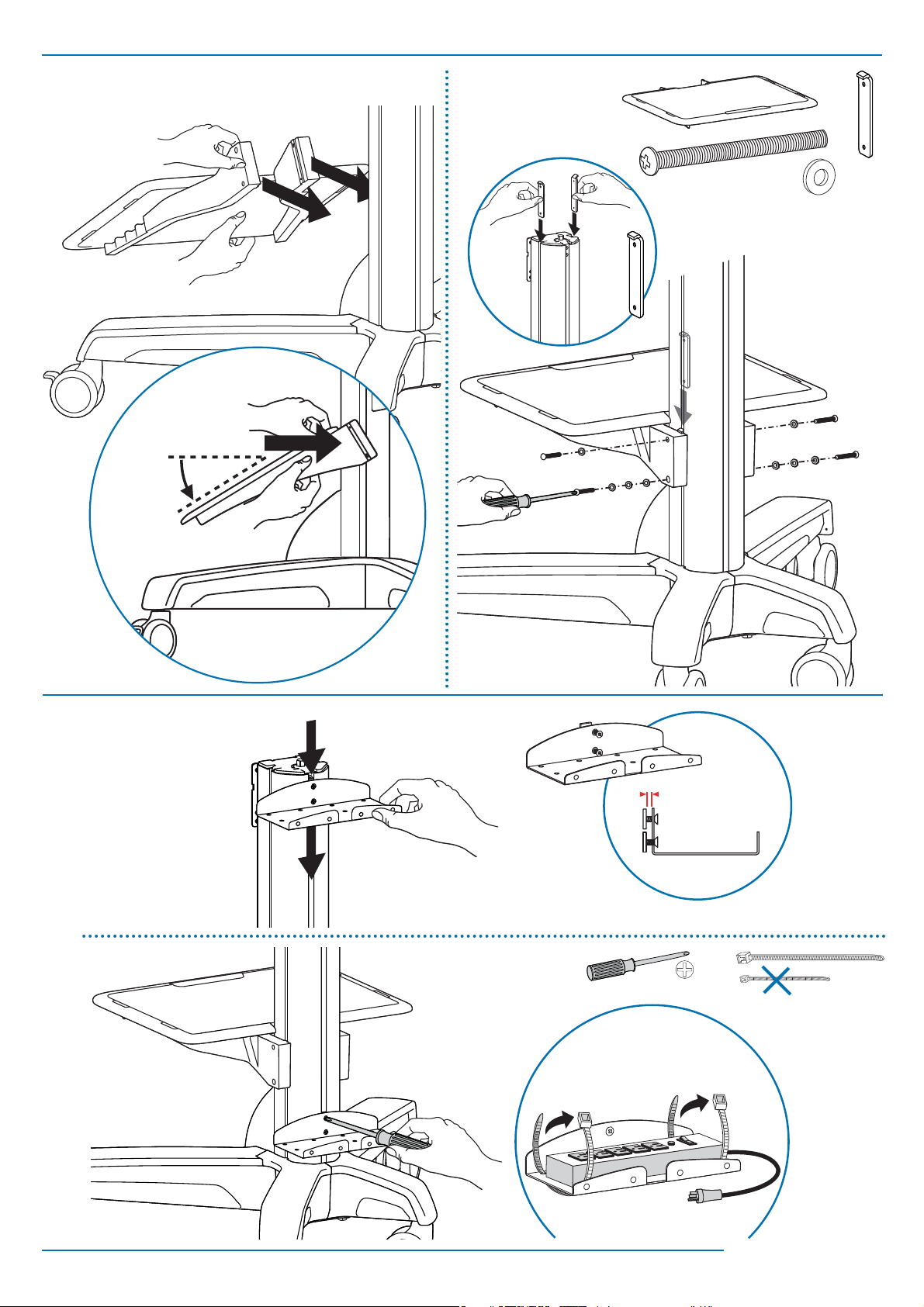
ab
5
4x
M6x8mm
4x
M6x14mm
4x2x
6
4x
M5 x 10mm
4x
200 mm
200 mm
400 mm
400 mm
888-24-064-M-00 rev. B • 12/08
600 mm
600 mm
5/14
Page 6

7
*
a
If a stand is already attached to your display,
*
remove it according to display manufacturer
directions. Place the display on a clean, fl at, padded
surface or, if you prefer, lean the display against a
stable, vertical surface.
Choosing Display Bracket Fasteners
Notice that several sizes of screws and spacers
have been provided for mounting the Tilt Mount
brackets to your large display. The instructions
and illustrations in this Reference Guide will help
you establish the appropriate combination of
fasteners based on the depth and diameter of
the mounting holes at the back of your display,
along with the design of the area surrounding
the mounting holes (Flat, Curved or Inset).
a Display Style
The design of the back of your display (fl at,
curved, inset) along with the diameter and depth
of the mounting holes at the back of your display
will determine which combination of hardware
you will use to attach the display bracket to your
display. Look at the back of your display to see
if the surface surrounding the mounting holes is
Flat, Curved or Inset.
Si el monitor incorpora una peana sobremesa,
*
extraiga la misma siguiendo las instrucciones de su
fabricante. Coloque el monitor sobre una superfi cie
plana, limpia y mullida con la pantalla hacia abajo
o, si lo prefi ere, apoye el monitor sobre una superfi cie vertical estable.
ESCOGIENDO LOS ELEMENTOS DE MONTAJE
PARA SU SOPORTE DE MONITOR
Se suministran diversos tamaños de tornillos
y espaciadores para el correcto montaje del
soporte a su monitor. Las instrucciones y dibujos
de esta Guía de referencia le ayudarán a elegir la
correcta combinación de tornillos, basada en la
profundidad y el diámetro de los huecos para el
montaje de la cubierta trasera de su monitor y en
el diseño del area que rodea a los orifi cios para
el montaje (plana, curva o con ranuras). Acuda a
la Instrucciones de Montaje para obtener información acerca del lugar dónde deben colocarse
los soportes en la parte posterior de su monitor,
una vez que haya elegido la correcta combinación de elementos para su situación.
a TIPO DE MONITOR
El diseño de la cubierta trasera de su monitor
(plano, curvo o con ranuras) junto al diámetro y
profundidad de los orifi cios para montaje en la
parte posterior de su monitor, determinarán la
correcta elección de elementos de montaje que
deberá utilizar para atornillar los soportes de
montaje a su monitor. Observe la cubierta trasera
de su monitor para comprobar si la superfi cie
que rodea los huecos para montaje es plana,
curva o con ranuras.
Si l’écran dispose déjà d’un pied, ôtez ce dernier
*
en suivant les recommandations du fabricant puis
posez le moniteur sur une surface plane, propre et
capitonnée ou appuyez le contre une paroi verticale parfaitement stable.
HOIX DES VIS DE FIXATION DES ETRIERS
Plusieurs tailles de vis et de séparateurs sont
fournies pour monter les étriers sur votre écran.
Les instructions et les illustrations de ce guide
vous aideront dans le choix de la vis adaptée au
diamètre et à la profondeur des trous de votre
écran et en fonction de son design arrière (plat,
bombé, évidé).
a STYLE DE L’ECRAN
Le design du dos de votre écran (plat, bombé,
évidé) ainsi que le diamètre et la profondeur
des trous détermineront le type de visserie que
vous utiliserez pour monter les étriers. Reportez
vous au Catalogue de Sélection du Kit d’Attaches
pour choisir la taille de vis adaptée à votre écran.
Regardez le dos de l’écran et vérifi ez si la surface
de celui-ci est plate, bombée ou évidée.
6/14
888-24-064-M-00 rev. B • 12/08
Page 7

7
b
Ø
b Hole Diameter
Four sets of display bracket screws have been
provided, each of a different diameter: 4mm,
5mm, 6mm, and 8mm. Compare the screws
with the diameter of the mounting holes at the
back of your display to fi nd the same size. NOTE:
Washer A is provided for use with the 4mm and
5mm screws while Washer B works with 6mm
and 8mm screws.
c
TOP
Arriba
Haut
b DIAMETRO DE LOS ORIFICIOS
Se incluyen 4 juegos de tornillos para el soporte
del monitor, con diferentes diámetros: 4mm,
5mm, 6mm. y 8mm. Compare los tornillos
suministrados con el diámetro de los huecos
para el montaje en la parte posterior de su
monitor para elegir el tamaño apropiado. NOTA:
Se incluye un juego de arandelas para su uso con
tornillos de 4 mm. y 5 mm. de diámetro y otro
modelo de arándelas para su uso con tornillos de
6 mm. y 8mm.
b DIAMETRE DES TROUS: 4 tailles de vis
sont fournies pour monter les étriers : 4mm,
5mm, 6mm et 8mm. Comparez les vis avec les
diamètres des trous au dos de l’écran. Note :
les rondelles A sont fournies pour les vis de
diamètre 4 et 5mm et les rondelles B pour les vis
de diamètre 6 et 8mm.
c Hole Depth
Lay the display bracket over the display mounting holes and measure the depth of the display
mounting holes with a slender stick.
888-24-064-M-00 rev. B • 12/08
c PROFUNDIDAD DE LOS ORIFICIOS
Coloque el soporte para monitor encima de los
orifi cios de montaje de su monitor y mida la
profundidad de estos huecos con un elemento
apropiado.
c PROFONDEUR DES TROUS: Posez les étriers
sur les trous et mesurez la profondeur des trous
avec un clou ou un trombone par exemple.
7/14
Page 8

7
d
Compare this measurement
Compare this measurement to the recommended screw (based on display back type and
diameter), taking into consideration the need for
a minimum amount of thread engagement (the
minimum thread engagement is the same as the
diameter of the screw, for instance, the minimum
thread engagement for an 8mm diameter screw
is 8mm).
If the screw is longer than your display’s mounting hole depth, you will need to compensate by
using one of the provided 6mm spacers - choose
Short Spacer A for 4mm and 5mm diameter
screws and Short Spacer B for 6mm and 8mm
screws*. If your display back design is Curved
or Inset, additional spacers have been provided
to compensate for variations in depth - choose
Long Spacer A for 4mm and 5mm diameter
screws and Long Spacer B for 6mm and 8mm
screws**.
Compare esta medida
Compare esta medida con el tornillo recomendado (basado en el tipo de cubierta trasera y
el diámetro de los orifi cios de montaje de su
monitor), teniendo en cuenta la necesidad de
una rosca mínima (la longitud mínima a enroscar
es la misma que el diámetro del tornillo, por
ejemplo, si el diámetro del tornillo es de 8 mm.,
la longitud mínima a enroscar es también de 8
mm.).
Si el tornillo es más largo que la profundidad
de los huecos para montaje de su monitor,
necesitará utilizar los espaciadores de 6 mm. que
se suministran: escoja un modelo de espaciador
corto para los tornillos de 4 mm. y 5 mm. de
diámetro y otro modelo de espaciador para los
tornillos de 6 mm. y 8 mm*. Si la cubierta posterior de su monitor es curva o con ranuras, emplee
los espaciadores suministrados para compensar las variaciones en profundidad : escoja un
modelo de espaciador largo para los tornillos
de 4 mm. y 5 mm. de diámetro y otro modelo de
espaciador para los tornillos de 6 mm. y 8 mm**.
Comparez cette mesure
Comparez cette mesure avec la taille des vis recommandée (en fonction du diamètre des trous
et de la forme de l’arrière de l’écran) et en tenant
compte de l’engagement minimum de la vis
dans l’écran (égale au diamètre de la vis). Si la vis
est plus longue que la profondeur du trou, vous
devrez utilisez un des séparateurs fournis : petit
séparateur A pour les vis de 4 et 5 mm et grand
séparateur B pour les vis de 6 et 8 mm*.
Si le dos de votre écran est bombé ou évidé
avec des glissières, vous disposez de séparateurs
supplémentaires pour compenser les différentes
profondeurs. Choisissez les grands séparateurs A
pour les vis de 4 et 5mm et les grands séparateurs B pour les vis de 6 et 8mm**.
8/14
888-24-064-M-00 rev. B • 12/08
Page 9

7
e
MM
MM
MM
Test Fasteners
It is important that you test the chosen fastener
combination to be sure it is the right size for
your display: partially thread the screw into the
display by hand with the correct combination of
washers and spacers (do not fully insert and do
not tighten screw at this time). If you feel resistance, remove the screw immediately and check
to see if a screw with a better matching size
has been provided. If you are unable to fi nd an
appropriate sized screw for your display, contact
Ergotron Customer Care. If the chosen combination of fasteners is correct for your situation,
mount the display brackets to your display as
instructed in the provided Tilt Mount Assembly
manual.
COMPRUEBE LOS CIERRES
Es importante que pruebe la combinación de
elementos elegidos para confi rmar que es del
tamaño adecuado para su monitor: enrosque
parcialmente con la mano el tornillo en el
monitor junto con la correcta combinación de
arandelas y espaciadores ( no lo inserte por
completo y no apriete el tornillo todavía). Si nota
resistencia, extraiga el tornillo y compruebe si
existe un tornillo más adecuado. Si no encuentra
un tamaño de tornillo apropiado para su
monitor, contacte con el Servicio de Atención
al Cliente de Ergotron. Si la combinación
de elementos elegida es apropiada para su
situación, instale los soportes en el monitor
siguiendo las instrucciones del Manual de
Montaje suministrado.
TESTEZ LES ATTACHES
il est important de tester la bonne combinaison
d’attaches pour être certain qu’elles sont de la
bonne taille : visser partiellement à la main les
vis avec les rondelles et les séparateurs. Si vous
sentez une résistance, ôtez la vis et choisissez
une autre vis à la bonne taille. Si aucune des
vis ne convient, contactez Ergotron. Si la
combinaison des attaches est bonne, montez les
étriers sur votre écran comme indiqué dans le
Manuel d’Installation.
888-24-064-M-00 rev. B • 12/08
9/14
Page 10

7
f
TOP
Arriba
Haut
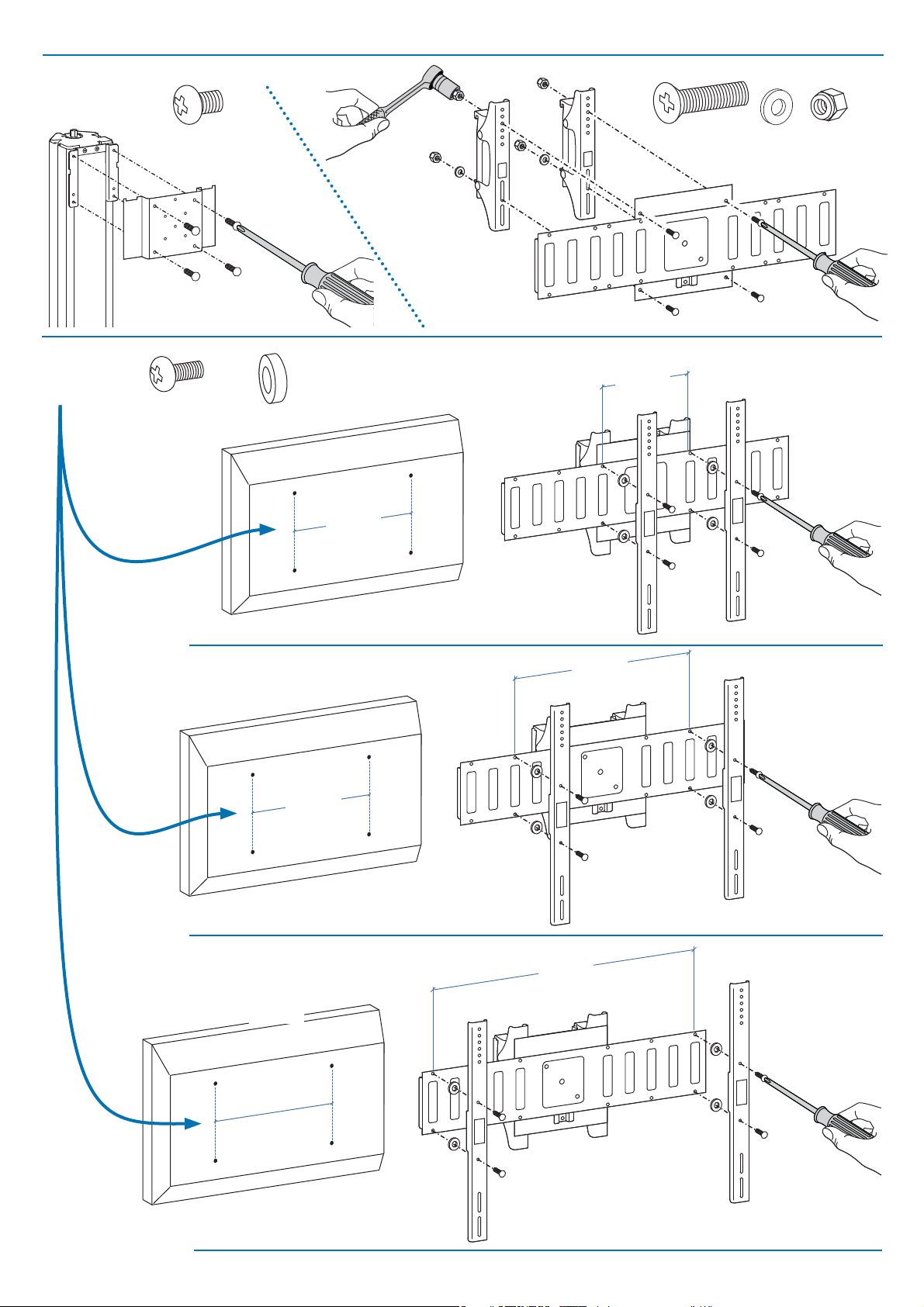
ATTACH BRACKETS TO DISPLAY
f Place Display Brackets (with pre-determined
fasteners) on back of display:
(y) The display brackets should be centered v erti-
cally on the back of the display - the distance
between the top of the bracket (y1) and the top
of the display should be the same as the distance
between the bottom of the bracket (y2) and the
bottom of the display.
(x) The display brackets should be mounted to
the outer-most hole sets or as wide as the rail
can support, not to exceed 600mm (23.6”) apart.
y1 = y
2
x < 600mm
ATORNILLE LOS SOPORTES
DE MONTAJE AL MONITOR
f Coloque los soportes de montaje en la cubi-
erta trasera del montor (con los elementos de
montaje seleccionados):
(y) Los soportes de montaje deben centrarse
verticalmente en la parte trasera del monitor .
La distancia entre el borde superior del soporte
(y1) y el borde superior del monitor debe ser la
misma que la distancia entre el borde inferior del
soporte (y2) y el borde inferior del monitor.
(x) Los soportes de montaje deben colocarse en
la parte exterior de los huecos de montaje o tan
separados como permita el ancho de la placa de
montaje, sin exceder de 600 mm. de separación.
FIXER LES ETRIERS A L’ECRAN
f Montez les étriers (avec les attaches adaptées)
au dos de l’écran.
(y) Le kit d’étriers doit être centré verticale-
ment au dos du moniteur : la distance entre le
haut de l’écran et le haut des étriers doit être
identique à celle entre le bas des étriers et le bas
du moniteur.
(x) Le kit d’étriers doit être installé dans les
trous les plus excentrés de l’écran dans la limite
toutefois d’un entraxe de 600 mm.
g
g Tighten screws with at least six, full, 360° revo-
lutions*, but do not over tighten; over tightening
may cause damage to display and/or brackets.
Six full turns will ensure a minimum thread
*
engagement roughly equal to the diameter of the
screw. For instance, if the screw diameter is 8mm,
the minimum thread engagement is also 8mm.)
MINIMUM THREAD ENGAGEMENT
LONGITUD MÍNIMA A ENROSCAR
ENGAGEMENT MINIMUM DES VIS
g Apriete los tornillos con al menos 6 giros
completos de 360º * , pero no los sobreapriete
pues podría dañar el monitor y/o los soportes de
montaje.
Seis giros completos aseguran una rosca mín-
*
ima del tornillo prácticamente igual al diámetro
del tornillo. Por ejemplo, si el diámetro del tornillo
es de 8 mm., la rosca mínima deberá ser también
de 8 mm.
g Serrez la vis en réalisant au moins 6 tours
complets* de 360°. Ne serrez pas trop car cela
pourrait endommager l’écran et/ou les étriers.
6 tours complets permettent d’engager la vis d’à
*
peu près la longueur de son diamètre. Par exemple,
si la vis a pour diamètre 8mm, la longueur engagée
sera également de 8 mm.
10/14
888-24-064-M-00 rev. B • 12/08
Page 11

8
9
2x
M4 x 16mm
ab
It is important that you adjust this product according to the weight of the mounted equipment as described in the following steps. Any time equipment
is added or removed from this product, resulting in a change in the weight of the mounted load, you should repeat these adjustment steps to ensure
safe and optimum operation.
Adjustments should move smoothly and easily through the full range of motion and stay where you set it. If adjustments are di cult and do not stay in the desired position, follow the
instructions to loosen or tighten the tension to create a smooth, easy adjustment motion. Depending on your product and the adjustment, it may take several turns to notice a di erence.
Los movimientos de ajuste deben poder realizarse de manera suave y rme dentro de la amplitud de movimiento permitida, y mantenerse donde usted los je. Si los ajustes son abruptos o
no permanecen en dicha posición, siga las instrucciones para a ojar o ajustar la tensión y suavizar así el movimiento. Dependiendo del producto y el ajuste, es posible que deba hacer varios
intentos hasta poder observar la diferencia .
Les réglages doivent s'e ectuer facilement et sans forcer dans toutes les positions et rester en place une fois réalisés. Si les réglages sont di ciles à e ectuer et ne restent pas en position, suivez
les instructions pour desserrer ou resserrer la tension a n que les mouvements soient plus aisés. Selon le produit que vous utilisez et le réglage, il faut parfois e ectuer plusieurs tours de vis
avant de remarquer une di érence.
Lift – Up and down
Elevación (arriba y abajo)
Ajustement en hauteur : bas et haut
14mm
Follow these instructions to tighten or loosen tension.
Siga estas instrucciones para ajustar o a ojar la tensión.
Suivez ces instructions pour desserrer ou resserrer la tension.
888-24-064-M-00 rev. B • 12/08
11/14
Page 12

10
1x
90˚
a
12/14
b
888-24-064-M-00 rev. B • 12/08
Page 13

11
1x
c
a
1x
M5x8mm
b
4x
2x
NOTE: Leave enough slack in cables to
allow full range of motion.
No deje el cable excesivamente tenso
Laisser du mou dans le câble
888-24-064-M-00 rev. B • 12/08
d
1x
13/14
Page 14

WARNING
STORED ENERGY HAZARD!
DO NOT OPEN TOWER OR REMOVE
SAFETY GUARD!
A primary mechanism within the
tower is under tension and can be
hazardous to people exposed to it
under certain extreme conditions. DO
NOT open the tower; DO NOT
attempt to service the cart/stand. DO
NOT remove safety guards or labels
designed to protect or inform of
possible hazards. Only
Ergotron-approved installers may
service or otherwise modify
cart/stand. Failure to heed this
Warning may result in serious
Personal Injury and Damage both to
the cart/stand and equipment.
WARNING
TIPPING HAZARD!
DO NOT allow children on Cart / Stand.
DO NOT route electric cords or
equipment cables within reach of
children. LOCK CASTERS when Cart is
stationary. Failure to comply with this
warning may result in Cart / Stand
instability leading to equipment damage
or personal injury.
WARNING
DO NOT load the Cart/Stand past
maximum weight capacity. DO NOT
mount a display larger than the
recommended size. Failure to comply
with warning may result in Cart/Stand
instability leading to equipment
damage or personal injury.
VHD: 50 - 90 lbs (22.7 - 40.8 kg)
kg
LD: 21-46 lbs (9.5 - 20.9 kg)
UHD: 90 - 120 lbs (41 - 54 kg)
30lbs
(15kg)
kg
kg
+30lbs
(15kg)
CAUTION
TIPPING HAZARD!
DO NOT move Cart with Display in highest
position. DO NOT push Cart from front or back
of Tower. DO NOT move Cart over cords or
uneven, dirty, soft or sloping surfaces. DO
NOT move Cart by pushing on Display. Failure
to comply with this caution may result in Cart
instability leading to equipment damage or
TO MOVE CART
1. Push Display down to lowest position on Cart.
2. Disconnect power cord and attach to Tower.
3.
4. Push Cart from side with hands on Tower.
personal injury.
Unlock casters; point casters in direction of travel.
820-982-00
14/14
888-24-064-M-00 rev. B • 12/08
 Loading...