


3x3 Template
Components
Command Post
8x
3x3
(76.2 mm)
8x
User's Guide
3/8" (9.5mm) -16 x 1"
(25.4mm) Hex Head Screws
for 2x2 Posts only
Tools Needed
8x
1" (25.4mm) Plastic Spacer
for 3x3 and 4x4 Posts only
9/16"
(14.3mm)
9/16"
(14.3mm)
3/8" (9.5mm)
Carbide drill bit
8x
3/8" (9.5mm)-16
Hex Nut
Floor application only
- optional Ergotron
Concrete Anchor Kit
3/8" (9.5mm) -16 x 2" (50.8mm)
Hex Head Screws
For 3x3 and 4x4 Posts only
8x
3/8" (9.5mm)
Flat Washer
8x
3/8" (9.5mm)
Split Lock Washer
4x
Ceiling application only 1/2" (12.7mm)
Anchor Rods
- customer
supplied
For the latest User Installation Guide please visit: www.ergotron.com
www.ergotron.com |
888-01-014-00 rev. F • 09/19
USA: 1-800-888-8458
|
Europe: +31 (0)33-45 45 600
|
China: 400-120-3051
|
Japan: japansupport@ergotron.com
1 of 6
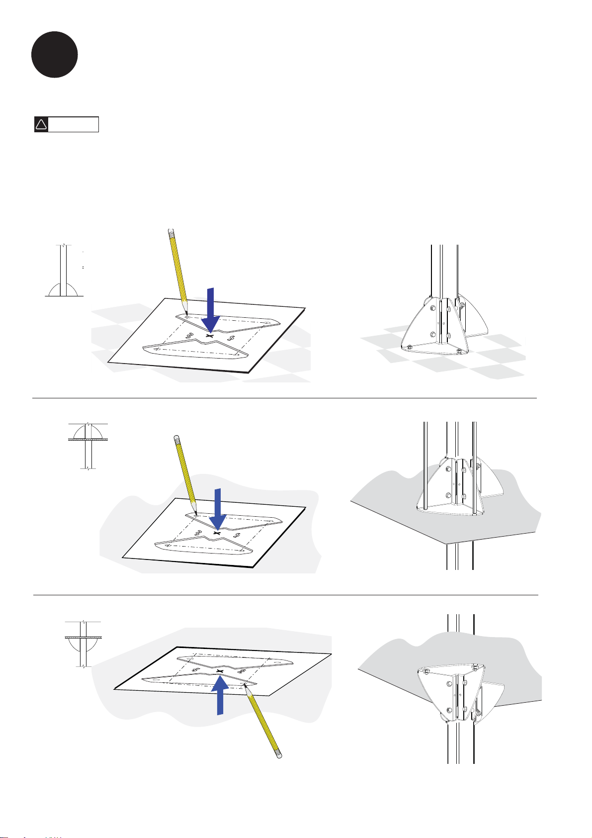
DETERMINE MOUNTING LOCATION
1
!
WARNING
The Support Base must be securely installed to ensure safety. Since Ergotron has no control over the type
of fl oor, ceiling, wall and/or ultimate mounting method, the user assumes all responsibility for this aspect of
the installation. If you have any questions in regard to your mounting system, see your building contractor.
Template
Mark four mounting holes
Floor
Above Ceiling
Below Ceiling
2 of 6
888-01-014-00 rev. F • 09/19

2
ASSEMBLE SUPPORT BASE
MOUNT BASE
3
Typical Floor Confi gurations
using optional Ergotron
Concrete Anchor Kit
-
Floor
888-01-014-00 rev. F • 09/19
3 of 6

3
MOUNT BASE
Below ceiling
- Ceiling
Below ceiling Above ceiling
4x
Typical Ceiling Confi gurations using customer
supplied 1/2" (12.7mm) Anchor Rods
Above ceiling
4 of 6
888-01-014-00 rev. F • 09/19

TIGHTEN BASE AROUND POST PLUMB UP THE POST
45
Floor Ceiling
400 lb force-inch
(33 lb force-foot)
(45 newton-meters)
SECURE BASE TO SURFACE
6
7
300 lb force-inch
(25 lb force-foot)
(34 newton-meters)
MOUNT EQUIPMENT AND ROUTE CABLES
Floor Ceiling
888-01-014-00 rev. F • 09/19
5 of 6

For Warranty visit: www.ergotron.com/warranty
For Service visit: www.ergotron.com
For local customer care phone numbers visit: http://contact.ergotron.com
www.ergotron.com |
© 2009 Ergotron, Inc. All rights reserved.
USA: 1-800-888-8458
6 of 6
|
Europe: +31 (0)33-45 45 600
|
China: 400-120-3051
|
Japan: japansupport@ergotron.com
888-01-014-00 rev. F • 09/19
 Loading...