

Page 1
1 of 15
888-83-080-G-00 rev. B • 01/19
www.ergotron.com |
USA: 1-800-888-8458
|
Europe: +31 (0)33-45 45 600
|
China: 400-120-3051
|
Japan: japansupport@ergotron.com
English, Español, Français, Deutsch, Nederlands, Italiano, Svenska, 日本語, 汉语
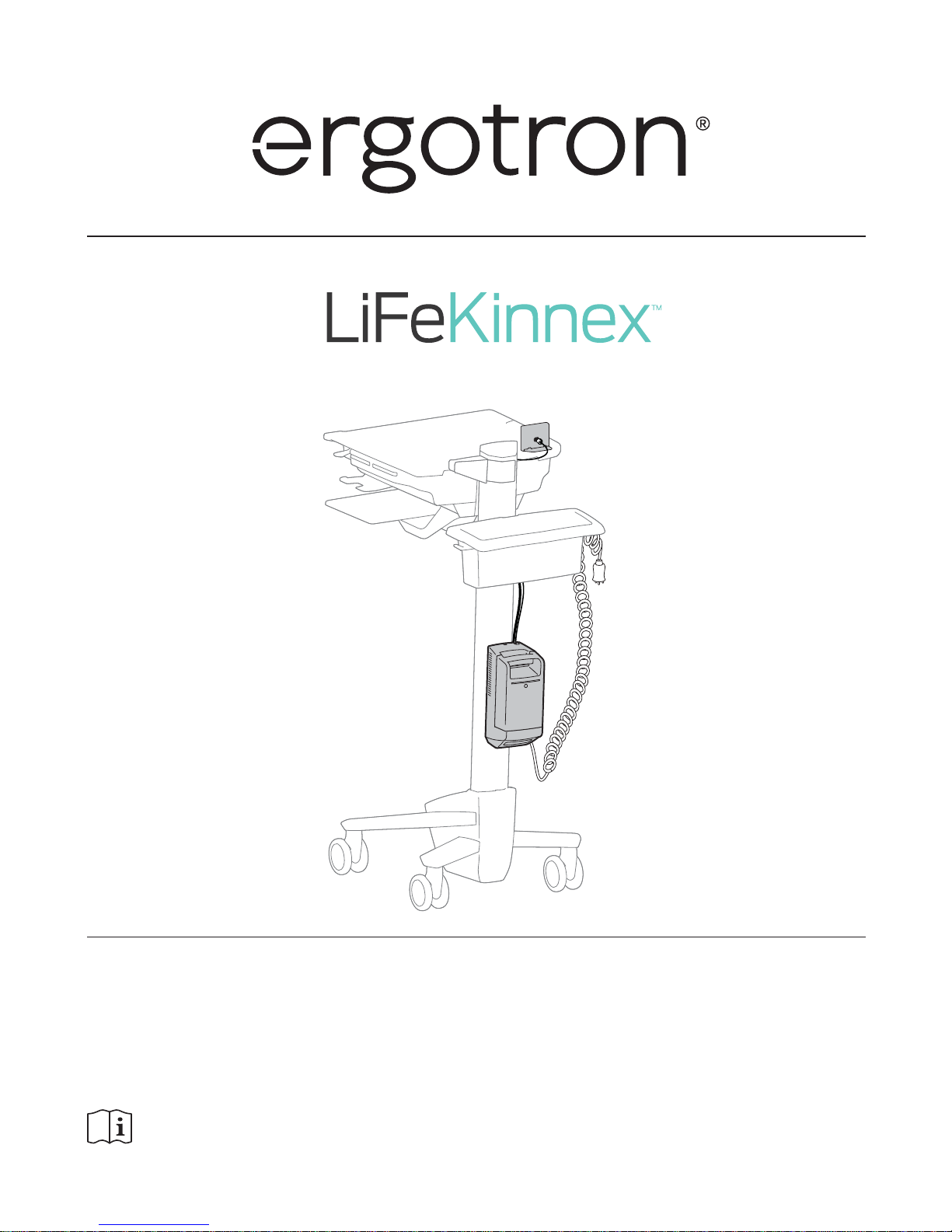
Power Module
User's Guide
English
For the latest User Installation Guide please visit: www.ergotron.com
The LiFeKinnex Power Module is intended to provide uninterrupted AC power to support AC powered computer equipment.
The Power Module is not intended to power medical products or devices.
Please review this manual before installing your equipment to learn how to use this product safely.
This product is a certifi ed medical power module according to IEC/EN 60601-1, as class I equipment. This power module is intended for use with IEC
60601-1 certifi ed equipment in the patient Environment and IEC 60601-1 and IEC 60950-1 certifi ed equipment outside of patient environment.
AC input: 100-240V~ 50/60-Hz. Max amps: 4.8 - 2.1A.
Manufactured for Ergotron by Green Cubes Technology www.greencubestech.com
Patents Ergotron.com/patents
Battery Sold Separately.
Page 2
2 of 15
888-83-080-G-00 rev. B • 01/19
CAUTION: To avoid the potential to pinch cables it is important to
follow the cable routing instructions in this manual. Failure to follow
these instructions may result in equipment damage or personal injury.
Equipment Electrical Safety
WARNING: Failure to observe the following Electrical Safety notices can result in fi re or death by electric shock.
Electrical cables can be hazardous. Misuse can result in fi re or death by electrical shock.
• Inspect power cables thoroughly before each use.
• Do not use cables that are damaged.
• Insert the plug completely into the outlet.
• Grasp the plug to remove from the outlet.
• Do not unplug by pulling on the cable.
• Do not use excessive force to make connections.
• Do not plug the cable into an extension cable.
• Do not remove, bend or modify any metal prongs or pins of cable.
• Do not drive, drag or place objects over the cable.
• Do not walk on the cable.
• Avoid overheating.
• Do not run cable through doorways, holes in ceilings, walls or fl oors.
Keep away from water.
• Do not use it when wet.
• Do not place in close proximity to fl ammable liquids or gases.
WARNING: Use of this equipment adjacent to or stacked with other equipment should be avoided because it could result in improper operation. If such use is
necessary, this equipment and the other equipment should be observed to verify that they are operating normally.
WARNING: Use of accessories, transducers and cables other than those specifi ed or provided by the manufacturer of this equipment could result in increased
electromagnetic emissions or decreased electromagnetic immunity of this equipment and result in improper operation.
CAUTION: The power disconnect for this equipment is the AC power cable.
Do not use this unit outdoors.
Never unplug this product from the outlet when your hands are wet.
Any modifi cations made to this device that are not approved, may void the authority granted to the user by the FCC to operate this equipment.
Ensure the product is connected to an outlet having the same confi guration as the plug. No adapter should be used with this product.
Ergotron does not accept any liability for damage if the unit is misused, incorrectly operated or inadequately repaired. Under these circumstances the warranty will be
void.
DANGER! Electrical cables can be hazardous.
Misuse can result in fi re or death by electrical shock.
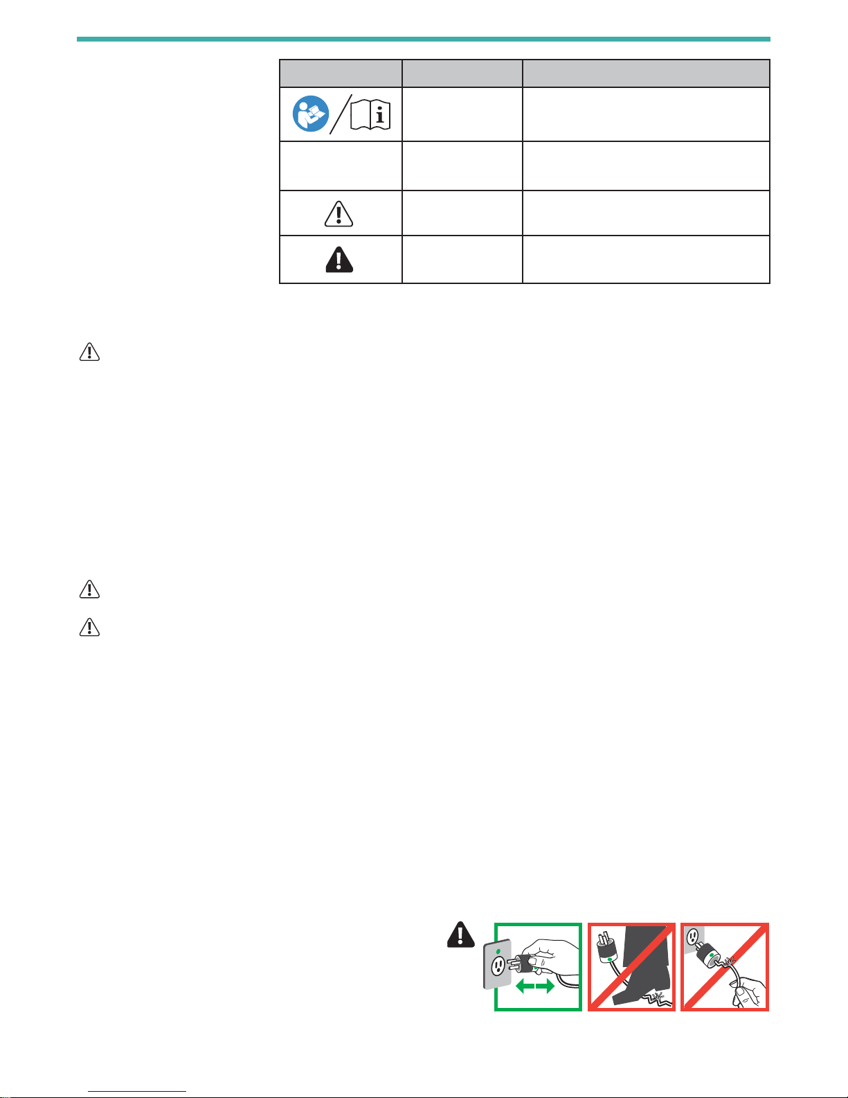
These symbols alert users of a safety
condition that demands attention. All users
should be able to recognize and understand
the signifi cance of the following Safety
Hazards if encountered on the product or
within the documentation. Children who
are not able to recognize and respond
appropriately to Safety Alerts should not use
this product without adult supervision!
Hazard Symbols Review
Safety
Symbol Signal Word Level of Hazard
INSTRUCTIONS
Refer to instruction manual/booklet.
Follow instructions for use.
CAUTION
A CAUTION indicates either potential damage to
hardware or loss of data and tells you how to avoid the
problem.
WARNING
A WARNING indicates either potential for property
damage, personal injury, or death.
DANGER
A DANGER indicates a hazardous situation that, if not
avoided, will result in death or serious injury.
Page 3

3 of 15
888-83-080-G-00 rev. B • 01/19
Do not attempt to connect the power modules in serial or parallel with any other power modules. This system was not designed to serve this purpose.
This power module shall be installed by qualifi ed personnel only. The system shall be always installed in the vertical direction as shown in the picture on cover page.
WARNING: DO NOT charge battery with any other charger.
WARNING: Battery contains magnets. Magnets may be harmful to persons with implanted medical devices. Keep battery at least 6" (152 mm) away from any
implanted medical devices.
WARNING: Keep battery and Power Module cool or at room temperature
Operating Temperature: 10°C to 40°C (50°F to 113°F)
Storage Temperature: -20°C to 45°C (-4°F to 113°F)
WARNING: Never attempt to open or service the battery.
WARNING: Never attempt to short circuit the battery or the Power Module intentionally.
WARNING: DO NOT drop, puncture or crush battery or expose to water.
WARNING: DO NOT dispose battery in fi re in any circumstances. Keep battery pack away from any hot source.
WARNING: DO NOT use battery if physical damage is evident.
WARNING: To avoid risk of electric shock, do not expose electrical component to water, cleaning solution or other potentially corrosive liquids or substances.
WARNING: To avoid risk of electric shock, this equipment must be connected to AC mains with protective earth.
WARNING: In rare case, if the power module and battery protection features fail, the battery may become overcharged and in some instances, it may become
extremely hot, possibly melting the plastics and releasing smoke.
If a battery begins to smoke or melts:
Unplug the cart, or if possible disconnect the battery from Power Module immediately.
Move the cart to a well-ventilated area.
Use a Carbon Dioxide, Dry Chemical, or appropriate foam fi re extinguisher to spray the hot battery. If a fi re extinguisher is not available, use copious amounts of
water, or cover the battery with sand. Exposure to vapor released from the battery is irritating to the eyes, skin, mucous membranes, and respiratory tract.
This may cause nausea, dizziness, and headache.
In case of direct contact to the battery's electrolyte:
Immediately fl ush eyes with water for at least 15 minutes.
Thoroughly rinse hands and other aff ected areas with water.
Promptly remove and wash any contaminated clothing.
In all cases, seek immediate medical attention!
Placement:
Do not expose the Power Module to direct sunlight or other heat source.
Ensure the operating environment is well ventilated to allow adequate dissipation of heat.
Ensure the Power Module surrounding area is clean and free from moisture.
Do not put heavy objects on the Power Module.
The socket outlet should be easily accessible and should be installed near the equipment.
AC Inlet power cords:
AC mains plug shall have the protective earth pin. By connecting the plug to the Power Module,
it shall have not more than 200mΩ to any part of the system metal case.
The connector shall be an IEC 60320 compliant C13 plug.
The power cords shall be IEC 60227 or HO5VV compliances.
AC Outlet power cords:
The connector shall be an IEC 60320 compliant C14 inlet.
The power cords shall be IEC 60227 or HO5VV compliant.
Safety
Page 4
4 of 15
888-83-080-G-00 rev. B • 01/19
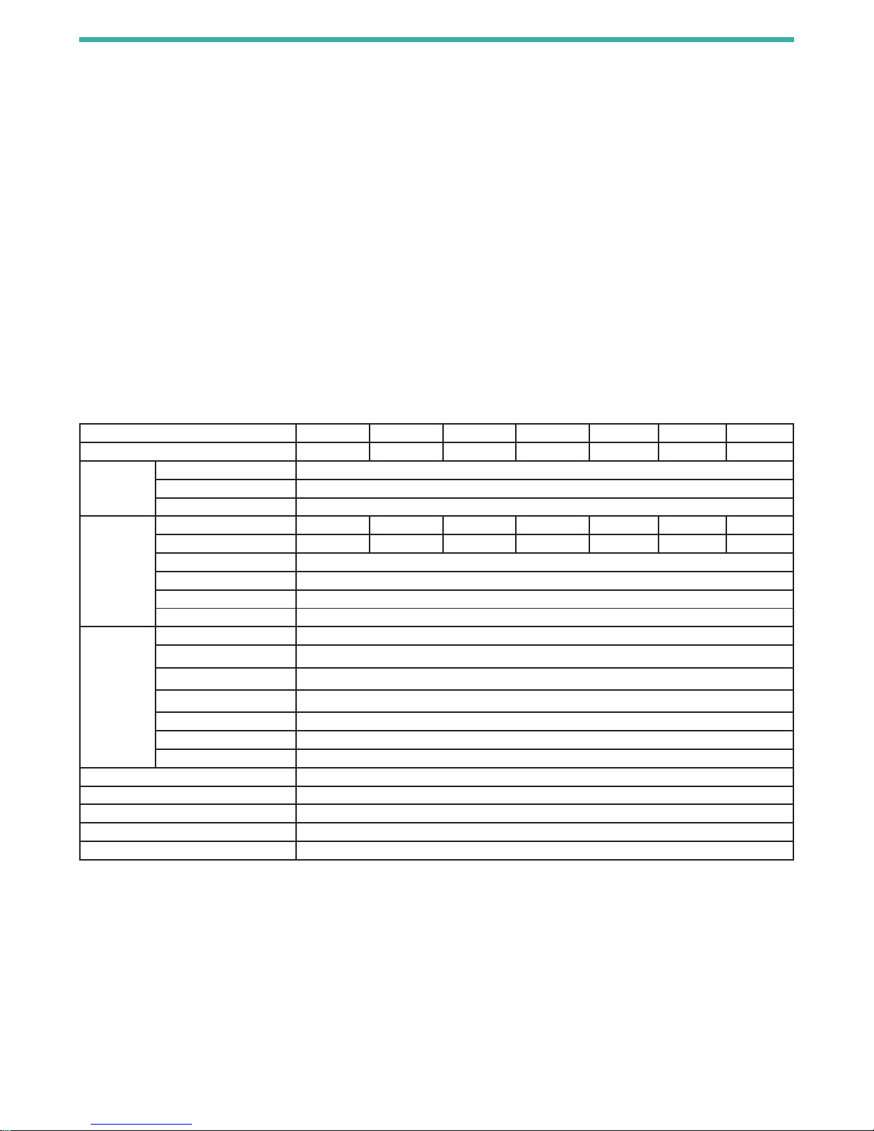
Features & Specifi cations
EMC levels are evaluated according to IEC60601-1-2/EN60601-1-2.
This power module was not designed to be water proof, therefore,
its classifi ed as IPX0 and also not evaluated as AP/APG equipment.
Certifi cation:
UL 60601-1 Safety of Medical Electrical Equipment
CAN/CSA C22.2 No. 601.1
IEC 60601-1
ICES-003 Issue 5, Class A
FCC Part 15 Class A
RoHS and REACH compliant material used.
This device complies with Part 15 of the FCC Rules. Operation is subject to the
following two conditions:
1) This device may not cause harmful interference.
2) This device must accept any interference received, including interference
that may cause undesired operation.
CAN ICES3(A)/NMB-3(A).
Changes or modifi cations not expressly approved by the Ergotron could void
the user's authority to operate the equipment.
Intended for institutional use.
Note: The emissions characteristics of this equipment make it suitable for use
in industrial areas and hospitals (CISPR 11 class A). If it is used in residential
environment (For which CISPR 11 class B is normally required) this equipment
might not off er adequate protection to radio-frequency communication services.
Mitigation measures, such as relocating or re-orienting the equipment may be
necessary.
Regulatory Model Number APB-1112G APB-1112H APB-1112B APB-1112 APB-1112C APB-1112D APB-1112F
Part Number 916-501-00 916-338-00 916-499-00 916-334-00 916-337-00 916-336-00 916-335-00
Input Voltage Range 100~ 240Vac
Frequency 50 / 60 Hz
Power Factor PF>0.94/230Vac PF>0,98/115Vac
Output Voltage Range (+/-3%) 100Vac 100Vac 120Vac 120Vac 127Vac 220Vac 230Vac
Frequency (+/-1 Hz) 50 60 50 60 60 60 50
Wave form Pure Sine Wave
Output Power (Continuous) 150VA
Output Power (Maximum) 180VA average up to 5 minutes
Output Power (Peak) 200VA average up to 1 second
Swappable
Battery
Lithium Iron
Phosphate
245Wh
916-333-00
Nominal Voltage 12.8V
Nominal Capacity 19.2Ah/245Wh
Charging Voltage 14.4V
Maximum Charging Current 15A
Maximum Discharge Current 21A
Approximate Weight 6.2lbs
Communication SMBUS
Operating Ambient Temperature 10° to 40°C
Transportation Temperature/Humidity -20° to +70°C/ 5% to 95%
Storage Temperature/Humidity -20° to +45°C/ 5% to 95%
Ambient Relative Humidity 20 to 90% Non-Condensing
Operating Altitude 4000 meters
Page 5
5 of 15
888-83-080-G-00 rev. B • 01/19
AB CD
1
2
3
4
mm
1x
1x
1x
4x
1x
1x
1x
1x
1x
1x
2x
1x
M3 x 8mm
5x
M5 x 10mm
4x
M4 x 8mm
1x
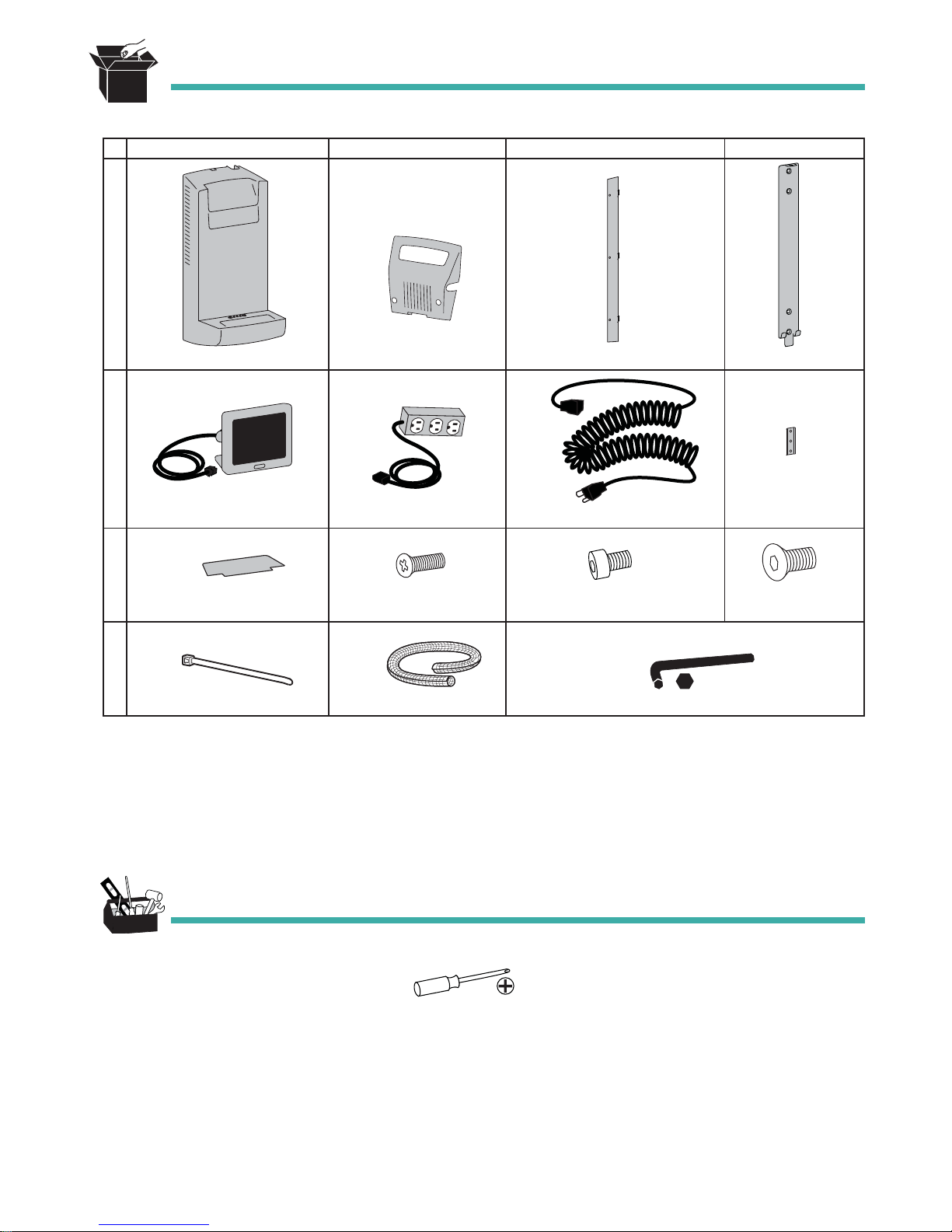
Battery Sold Separately.
Lithium Iron Phosphate 245Wh, 916-333-00
Tools Needed
Components
Power Module
Display
Cable Wrap
Cable Tie
Display Base
Hex Wrench
Bottom Cover
Power Strip
Screw
Back Cover
Coiled Cord
Screw
Mounting Bracket
T-Slot Bracket
Screw
Page 6

6 of 15
888-83-080-G-00 rev. B • 01/19
1
2
180˚
180˚
M5 x 10mm
4x
Remove any T-Slot mounted components from your cart that would interfere with the installation of the Power Module.
SV41 cart shown here.
Assemble the Mounting Bracket and T-Slot Brackets.
Top View
Page 7

7 of 15
888-83-080-G-00 rev. B • 01/19
mm
3
4
Attach the T-Slot Bracket to your cart's T-Slot.
Attach the Display to your desired location on your cart.
Page 8

8 of 15
888-83-080-G-00 rev. B • 01/19
5
6
Open your cart's storage area and place the Power Strip in there.
Route the Display and Power Strip cables down through storage area to the base of the cart.
Plug in all 3 cables to the Power Module.
WARNING: Connecting electrical equipment to the outlet
eff ectively leads to creating a medical system and the result can
be a reduced level of safety.
Page 9

9 of 15
888-83-080-G-00 rev. B • 01/19
7
8
8
M3 x 8mm
2x
4x
Attach Bottom Cover routing Coiled Cord out the side and routing Display and Power Strip cables up through the
back channel.
Page 10

10 of 15
888-83-080-G-00 rev. B • 01/19
9
10
M3 x 8mm
3x
M4 x 8mm
1x
mm
Attach Back Plate keeping Display and Power Strip cables in the Channel.
Attach Power Module to Mounting Bracket on Cart and secure with a screw.
The Power Module sets onto the bottom hooks and then lift slightly to align the upper tab on
the bracket with the hole where the screw is then secured
Page 11

11 of 15
888-83-080-G-00 rev. B • 01/19
11
Dock the Battery by placing on the Power Module. (Battery Sold Separately.)
Do not drop Battery on Power Module. When Battery is properly docked, the Battery's fuel gauge will light for 3
seconds. If Battery is not properly docked, do not push on Battery. Remove Battery and repeat docking.
To charge Battery: plug Power Module into wall outlet and turn on Display.
DISPLAY MUST BE TURNED ON FOR BATTERY TO CHARGE.
To Remove Battery, squeeze handle and pull off .
Once the Battery is removed, Power Module will
continue to supply power to devices for 2 minutes. To
avoid losing power to devices, ensure that a charged
battery is replaced on Power Module or unit is plugged
into AC power.
Page 12

12 of 15
888-83-080-G-00 rev. B • 01/19
The Display shows battery capacity both in percentage and operational time remaining. The time
remaining is calculated based on average actual load. This information is to be used to determine
when to swap with a charged battery or to plug in Power Module.
Push button to turn on.
Display will automatically dim after 1 min, press button once to brighten display.To turn off , push and
hold button until screen turns off .
DISPLAY MUST BE TURNED ON FOR BATTERY TO CHARGE.
RED plug: Not Charging and time to fully discharged is less than 5 minutes
RED Bar: State of charge is greater than 5% and less than or equal to 10%
RED Bars: State of charge is greater than 10% and less than or equal to 20%
GREEN Bars: State of charge is greater than 30% and less than or equal to 50%
GREEN Bars: State of charge is greater than 50% and less than or equal to 70%
YELLOW Bars: State of charge is greater than 20% and less than or equal to 30%
GREEN Bars: State of charge is greater than 70% and less than or equal to 90%
GREEN Bars: State of charge is greater than 90%
RED: Error status. Contact Ergotron Customer Care for assistance.
Wifi status. This symbol will blink to notify user that Wifi needs to be confi gured.
Instructions on connecting device to Wi-Fi network can be found at www.ergotron.com/lifekinnex
During charging, LCD shows charging symbol with time remaining on battery.
GREEN Bars: In battery mode, LCD shows time for battery run time
RED Battery: 2-minute countdown timer when battery is removed.
Power cord is plugged into an AC outlet and there is no battery on the unit.
Display
Page 13

13 of 15
888-83-080-G-00 rev. B • 01/19
SERVICE AND MAINTENANCE
The Power Module shall be installed and repaired by qualifi ed personnel only.
The cleaning and preventive inspection should be performed by individuals with previous training.
Prior to cleaning or storing the Power Module for extended periods, the system should be placed in shut down mode. To do this,
unplug the AC power source, remove battery, then power off the Power Module by holding the Display button for 3 seconds.
Cleaning methods include:
Use a vacuum to clean out the dust from the opening of the fan and contact pin of the power bay.
Dampen cloth with water or cidex solution to clean the surface.
Do not use any alcohol or ammonia based solution to clean the surface.
Avoid spilling liquid into or on the Power Module.
When not using the battery for long periods, battery should be fully charged before storage and charged regularly during storage.
Keep spring pin contacts free of dust and debris.
OPERATING MODE OPERATION DETAILS
AC supply mode By connecting to AC power source, the Power Module will use the AC power to support both charging
and output loading.
The swappable battery pack and the backup battery will be charged to full when AC power is connected.
The charging current depends upon the output loading. The remaining power will be used to charge the
battery.
Battery supply mode The Power Module will work as a battery to provide continuous AC output to varying loads.
The swappable battery pack will also charge the backup battery on the Power Module to make sure
backup battery capacity is enough to handle the swapping.
During the swapping, the display will show a 2 minute countdown and after 2 minutes, power will no
longer be provided to devices. In the event that battery fully depletes before AC power is supplied or
battery pack is replaced with a charged battery pack, the Power Module will shut down and power will no
longer be provided to devices.
Standby mode Power Module will enter standby mode when button on the display is pressed for more than 3 seconds.
No charging activity during this mode.
AC output / Inverter shuts down.
Power Module enters low power mode.
To return back to operating mode, simply press the display button.
Shut down mode For Power Module to enter shut down mode, both battery and AC power source must be removed.
To force the shut down mode, unplug the AC power source, remove the battery, then power off the
Power Module by holding the Display button for 3 seconds.
Alternatively, the Power Module will automatically enter shut down mode if the Battery is removed and
no new battery is placed on the Power Module. The Display will show a 2 minute count down, after
which power will no longer be provided to devices. The Display screen will then shut off and the system
will shut down.
To return back to operating mode, place a battery on the Power Module or connect AC power source to
the Power Module and press the display button.
EQUIPMENT & ACCESSORIES DISPOSAL
1. Please dispose of or recycle all batteries in accordance with local law
2. All Electronics should be recycled through an electronics recycler.
3. Remaining plastics and metals can be recycled through a commercial recycler.
Page 14

14 of 15
888-83-080-G-00 rev. B • 01/19
1
2
3
4
5
POWER MODULE INTERFACE:
1. RJ55: Connect Display Module (916-339) to this connector
2. Reset: Reset button to reset the whole system
3. USB : USB Connector for confi guration
4. AC IN 100V ~ 240V: Connect AC input coiled cord here
5. AC OUT: Connect AC output cable module here
ERGOTRON ELECTROMAGNETIC GUIDANCE AND MANUFACTURER’S DECLARATION
Guidance and Manufacturer’s Declaration – Electromagnetic Emissions
The Power Module is intended for use in the electromagnetic environment speci ed below. The customer or the user of the Power Module should assure that it is used in such
an environment.
Emissions Test Compliance Electromagnetic environment – guidance
RF Emissions
CISPR 11
Group 1 The Power Module uses RF energy only for its internal function. Therefore, its RF emissions are very low and unlikely to
cause any interference in nearby electronic equipment.
RF Emissions
CISPR 11
Class A The Power Module is suitable for use in all establishments other than domestic and those directly connected to the
public low-voltage power supply network that supplies buildings used for domestic purposes.
Harmonic Emissions
IEC 61000-3-2
Class A
Voltage uctuations/
icker emissions
IEC 61000-3-3
Complies
Guidance and Manufacturer’s Declaration – Electromagnetic Immunity
The Power Module is intended for use in the electromagnetic environment speci ed below. The customer or the user of the Power Module should assure that it is used in such
an environment.
Immunity Test IEC 60601
Test Level
Compliance
Level
Electromagnetic environment - guidance
Electrostatic Discharge (ESD)
IEC 61000-4-2
±8 kV contact
±15 kV air
Complies Floors should be wood, concrete, or ceramic tile. If oors are covered with synthetic
material, the relative humidity should be at least 30%
Radiated RF EM elds
IEC 61000-4-3
10V/m
80 MHz – 2.7 GHz
complies
Radiated RF EM elds: Proximity
elds from RF wireless
communications equipment
IEC 61000-4-3
IEC 60601-1-2:2014 table 9 complies WARNING: Portable RF communications equipment (including peripherals such as
antenna cables and external antennas) should
be used no closer than 30 cm (12 inches) to any part of LifeKinnex Power Module,
including cables speci ed by the manufacturer. Otherwise, degradation of the
performance of this equipment could result.
Electrical Fast Transient/Burst
IEC 61000-4-4
±2 kV for power supply lines Complies Mains power quality should be that of a typical commercial or hospital environment.
Surge
IEC 61000-4-5
±1 kV di erential mode
±2 kV common mode
Complies Mains power quality should be that of a typical commercial or hospital environment
Conducted Immunity
IEC 61000-4-6
3 V rms
0.15 MHz – 80 MHz
6 V rms (ISM)
80 % AM at 1 kHz
complies
Voltage Dips, short interruptions,
and voltage variations on power
supply input lines
IEC 61000-4-11
0% Ut for 0.5 cycle
70% Ut for 25 cycles
0% Ut for 5 seconds
Complies Mains power quality should be that of a typical commercial or hospital environment.
Power Frequency (50/60 Hz)
Magnetic Field
IEC 61000-4-8
30 A/m Complies Power frequency magnetic elds should be at levels characteristic of a typical
location in a typical commercial or hospital environment.
Note: U
T
is the AC mains voltage prior to application of the test level
Page 15

15 of 15
888-83-080-G-00 rev. B • 01/19
© 2018 Ergotron, Inc. All rights reserved. Manufactured for Ergotron by Green Cubes Technology www.greencubestech.com.
LiFeKinnex™ is a registered trademark of Ergotron, Inc.
www.ergotron.com |
USA: 1-800-888-8458
|
Europe: +31 (0)33-45 45 600
|
China: 400-120-3051
|
Japan: japansupport@ergotron.com
NOTE: When contacting customer service, reference the serial number.
For local customer care phone numbers visit: http://contact.ergotron.com
For Service visit: www.ergotron.com
For Warranty visit: www.ergotron.com/warranty
 Loading...