

Page 1
User's Guide
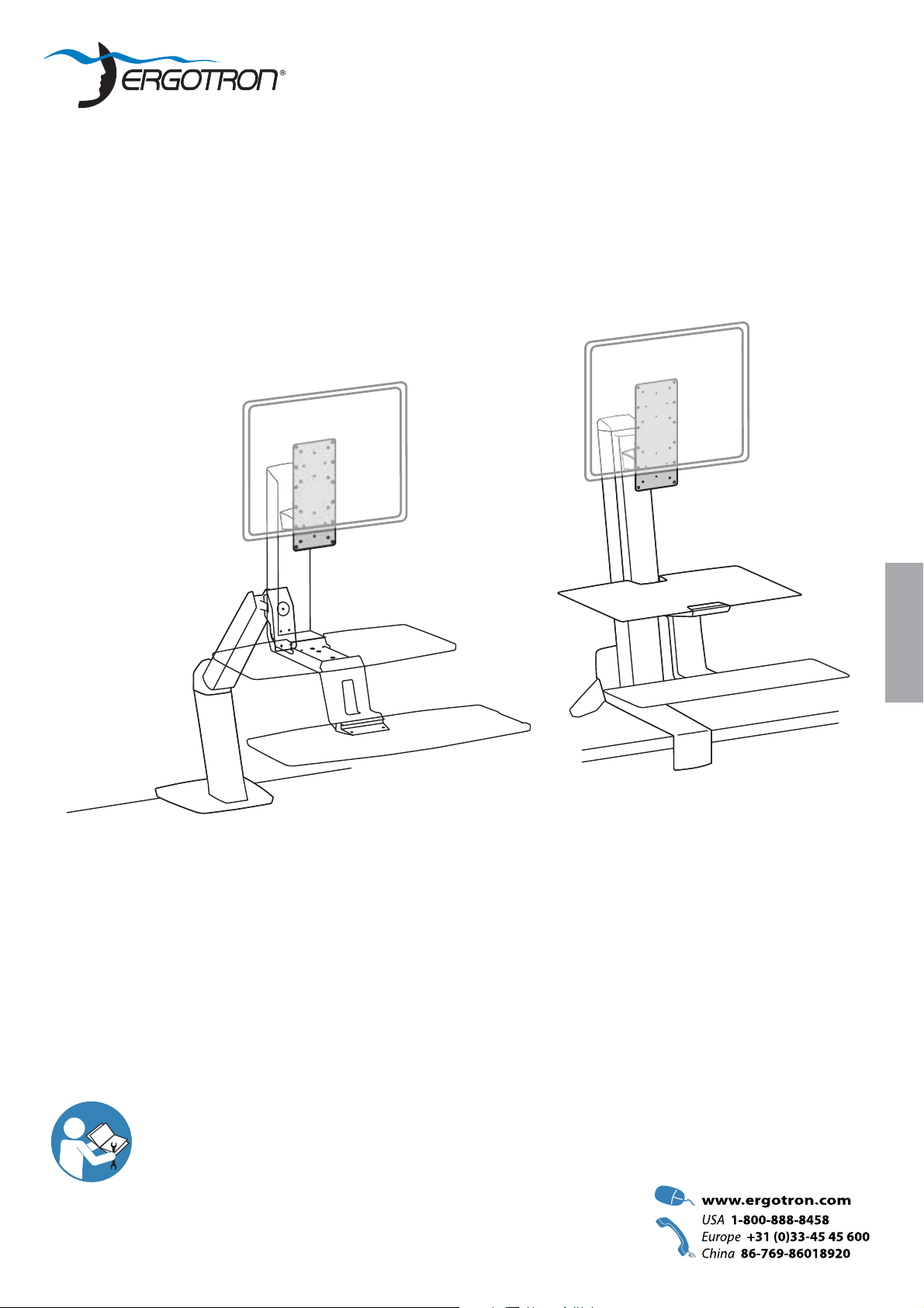
Single Monitor Tall User Kit
for WorkFit, A & S Products
ENGLISH
For the latest User Installation Guide please visit: www.ergotron.com
User's Guide - English
Guía del usuario - Español
Manuel de l’utilisateur - Français
Gebruikersgids - Deutsch
Benutzerhandbuch - Nederlands
Guida per l’utente - Italiano
Användarhandbok - svenska
ユーザーガイド:日本語
用户指南 : 汉语
888-97-352-G-00 rev. B • 05/14
1 of 7
Page 2
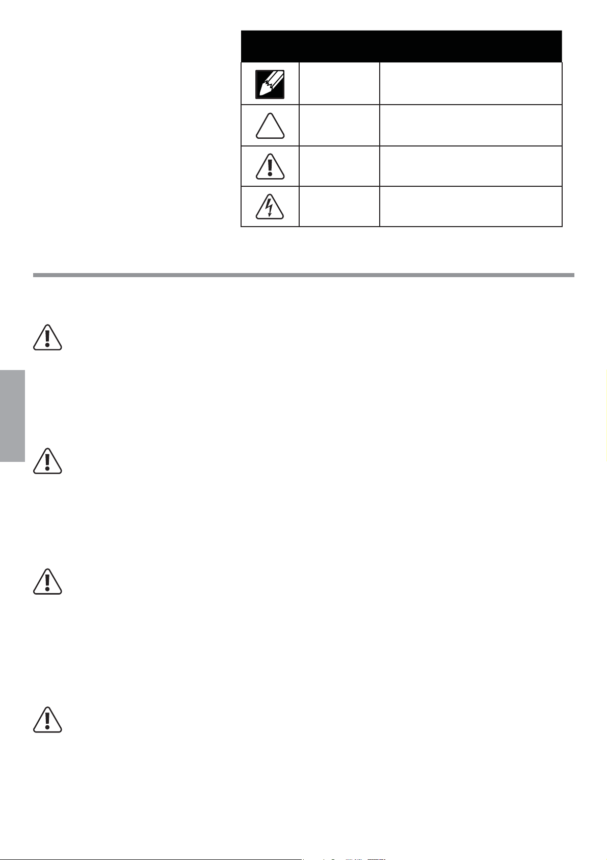
Hazard Symbols
Symbol Signal Word Level of Hazard
Review
These symbols alert users of a safety condition that demands attention. All users should
be able to recognize and understand the
signifi cance of the following Safety Hazards
if encountered on the product or within the
documentation. Children who are not able
to recognize and respond appropriately to
Safety Alerts should not use this product without adult supervision!
Safety
WARNING: Weight Capacity Restriction!
Make sure the total combined weight of Display and Single Monitor Tall User Kit is less than the specifi ed weight
capacity of the product you are attaching to. Failure to follow this warning will create an unstable situation that
may result in product damage and/or personal injury.
NOTE
CAUTION
WARNING
ELECTRICAL
A NOTE indicates important information that helps you
make better use of this product.
A CAUTION indicates either potential damage to
hardware or loss of data and tells you how to avoid the
problem.
A WARNING indicates either potential for property damage, personal injury, or death.
An Electrical indicates an impending electrical hazard
which, if not avoided, may result in personal injury, re
and/or death.
ENGLISH
WARNING: Portrait/Landscape Lock-out screw MUST be installed!
Make sure the P/L Lock-out screw is installed before attaching the Single Monitor Tall User Kit. Failure to follow
this warning will create an unstable situation where the display may rotate causing product damage and/or
personal injury.
WARNING: Make sure you use the specifi ed screws for each connection point. Using incorrect screws may
cause product damage or create an unstable situation that could lead to product damage and/or personal injury.
WARNING: Do not over tighten screws. Over tightening screws may cause product damage.
2 of 7
888-97-352-G-00 rev. B • 05/14
Page 3
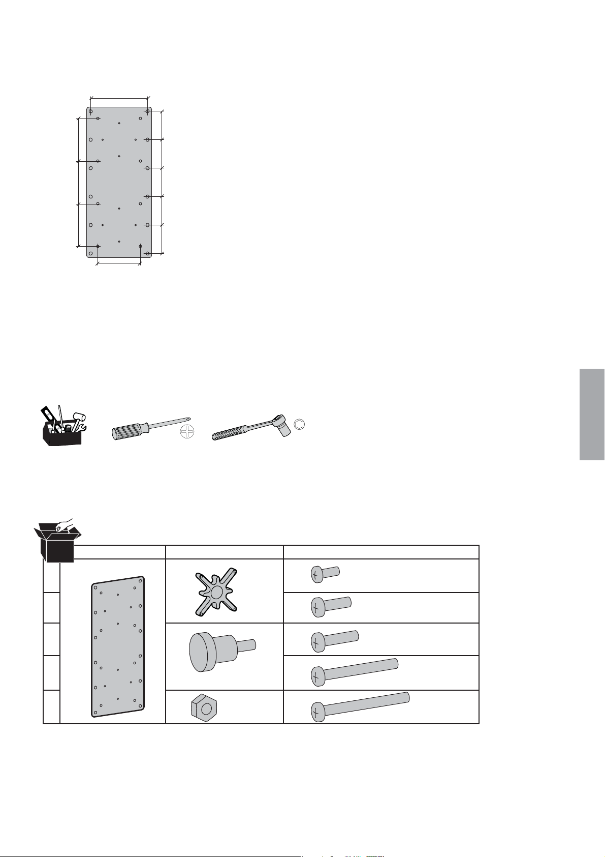
Features & Specifi cations
100mm
(3.94")
75mm
(2.95")
75mm
(2.95")
75mm
(2.95")
75mm
(2.95")
50mm (1.97")
50mm (1.97")
50mm (1.97")
50mm (1.97")
50mm (1.97")
Tools Needed
ENGLISH
Components
AB C
1
1x
2
3
4
5
1x
4x
4x
M4x10mm
M4
1x
8x
2x
4x
2x
7mm
M3x6mm
M4x10mm
M4x12mm
M4x28mm
M4x30mm
888-97-352-G-00 rev. B • 05/14
3 of 7
Page 4

1
Attach Portrait/Landscape Lock-out screw.
2
0°
WARNING: Portrait/Landscape Lock-out screw
MUST be installed!
Make sure the P/L Lock-out screw is installed
before attaching the Single Monitor Tall User
Kit. Failure to follow this warning will create an
unstable situation where the display may rotate
causing product damage and/or personal injury.
Attach plate.
NOTE: You can raise your monitor 150mm or 100mm.
1x
M3x6mm
ENGLISH
4x
4x
7mm
WARNING: Make sure you use the specifi ed screws for each connection point. Using incorrect screws may
cause product damage or create an unstable situation that could lead to product damage and/or personal injury.
150mm
(5.91")
M4x10mm
M4
100mm
(3.94")
2x
2x
M4x10mm
M4
4 of 7
7mm
888-97-352-G-00 rev. B • 05/14
Page 5

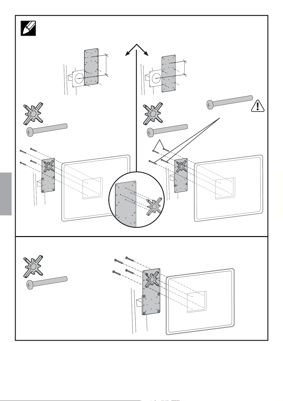
3
Attach display.
WARNING: Make sure you use the specifi ed screws for each connection point. Using incorrect screws may
cause product damage or create an unstable situation that could lead to product damage and/or personal injury.
WARNING: Do not over tighten screws. Over tightening screws may cause product damage.
100x100mm Mounting Holes
4x
M4x10mm
4x
M4x10mm
150mm
(5.91")
2x
M4x10mm
100mm
(3.94")
2x
M4x10mm
2x
M4x12mm
CAUTION: Use
these longer screws
only when going
through 2 plate
thickness.
ENGLISH
75x75mm Mounting Holes
4x
4x
M4x10mm
NOTE: For displays with recessed mounting holes, see instructions on next page.
888-97-352-G-00 rev. B • 05/14
M4x10mm
5 of 7
Page 6
NOTE: User spacer and specifi ed screws if your display has recessed mounting holes.
100x100mm Recessed Mounting Holes
4x
M4x28mm
150mm
(5.91")
2x
M4x28mm
100mm
(3.94")
2x
M4x30mm
CAUTION: Use
these longer screws
only when going
through 2 plate
thickness.
ENGLISH
75x75mm Recessed Mounting Holes
4x
M4x28mm
6 of 7
888-97-352-G-00 rev. B • 05/14
Page 7

4
Adjust your mounting solution to handle the added weight.
Adjustments should move smoothly and easily through the full range of motion and stay where you set it. If adjustments
are diffi cult and do not stay in the desired position, follow the instructions to loosen or tighten the tension to create a
smooth, easy adjustment motion. Depending on your product and the adjustment, it may take several turns to notice a
difference.
Set Your Workstation to Work For YOU!
Adjustment Step
Learn more about ergonomic computer use at:
www.computingcomfort.org
Height Position top of screen slightly below eye level.
Position keyboard at about elbow height with wrists fl at.
Distance Position screen an arm's length from face—at least 20” (508mm).
Position keyboard close enough to create a 90˚ angle in elbow.
Angle Tilt screen to eliminate glare.
Tilt the keyboard back 10° so that your wrists remain fl at.
To Reduce Fatigue
Breathe - Breathe deeply through your nose.
Blink - Blink often to avoid dry eyes.
Break • 2 to 3 minutes every 20 minutes
• 15 to 20 minutes every 2 hours.
Service and Warranty
For local customer care phone numbers visit: http://contact.ergotron.com
NOTE: When contacting customer
service, reference the serial number.
ENGLISH
888-97-352-G-00 rev. B • 05/14
7 of 7
 Loading...