

Page 1
www.ergotron.com
User's Guide - English
Guía del usuario - Español
Manuel de l’utilisateur - Français
Gebruikersgids - Nederlands
Benutzerhandbuch - Deutsch
Guida per l’utente - Italiano
Användarhandbok - svenska
ユーザーガイド : 日本語
用户指南 : 汉语
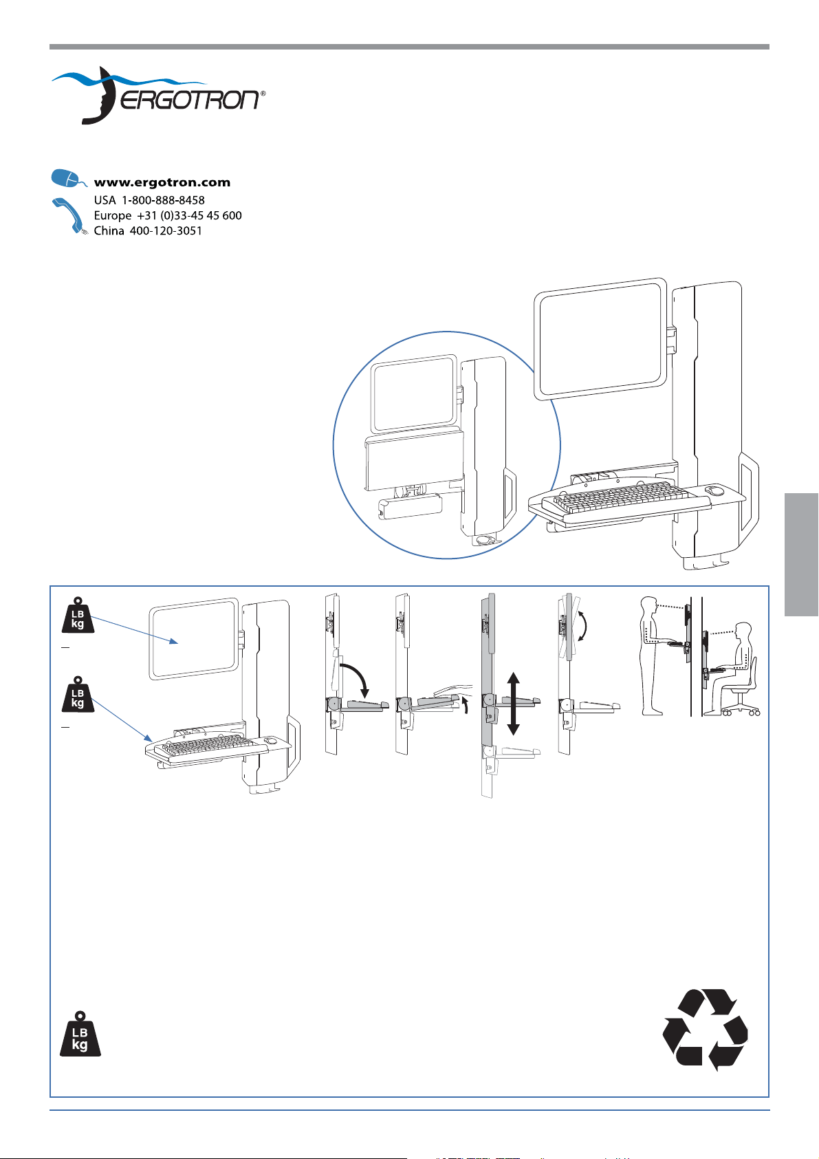
StyleView Sit-Stand VL
High Tra c Areas
< 25 lbs
(11.34 kg)
< 4 lbs
(1.8 kg)
Important! You will need to adjust this product after installation is complete. Make sure all your equipment is
properly installed on the product before attempting adjustments. This product should move smoothly and easily
through the full range of motion and stay where you set it. If movements are too easy or di cult or if product
does not stay in desired positions, follow the adjustment instructions to create smooth and easy movements.
Depending on your product and the adjustment, it may take many turns to notice a di erence. Any time
equipment is added or removed from this product, resulting in a change in the weight of the mounted load, you
should repeat these adjustment steps to ensure safe and optimum operation.
ENGLISH
Max weight 29 lbs (13.2 kg)
CAUTION: DO NOT EXCEED MAXIMUM LISTED
WEIGHT CAPACITY. SERIOUS INJURY OR
PROPERTY DAMAGE MAY OCCUR!
888-61-042-G-01 rev. E • 08/16
Reduce.Reuse.Recycle
1 of 15
Page 2
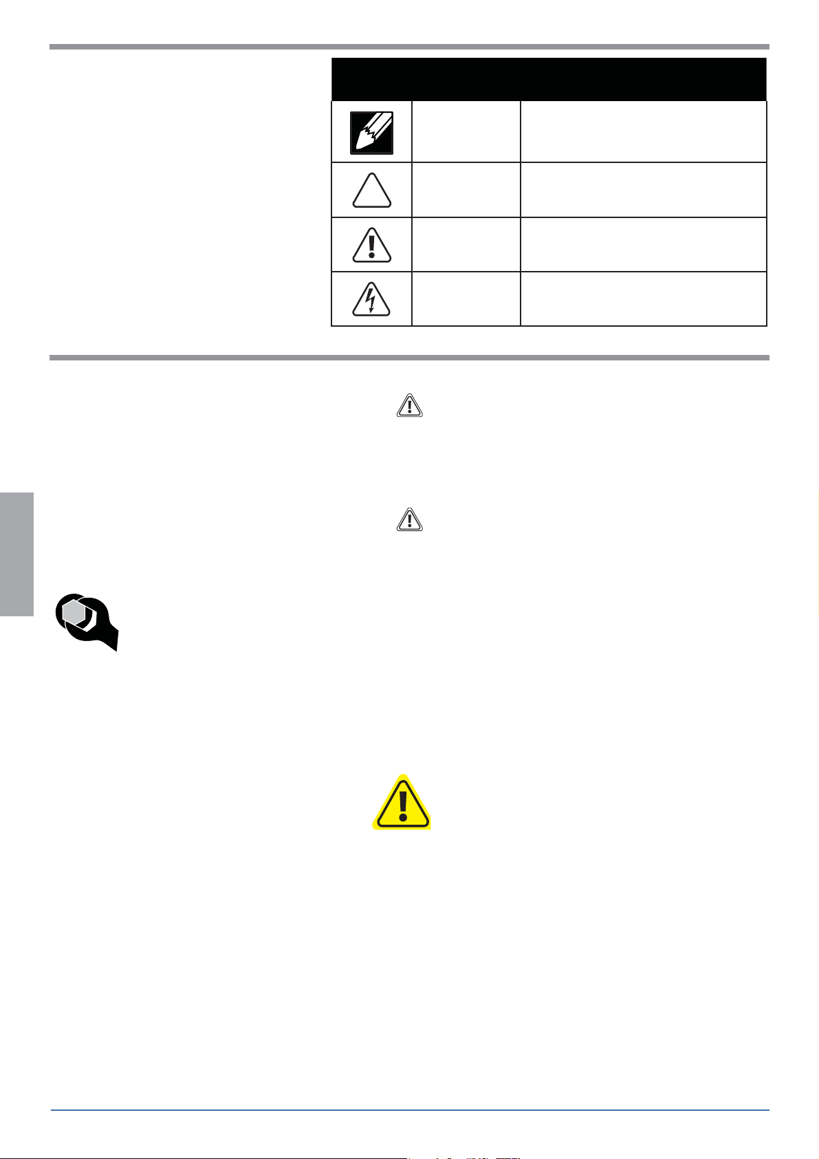
Hazard Symbols Review
Symbol Signal Word Level of Hazard
These symbols alert users of a safety condition that
demands attention. All users should be able to
recognize and understand the signi cance of the following Safety Hazards if encountered on the product
or within the documentation. Children who are not
able to recognize and respond appropriately to Safety
Alerts should not use this product without adult
supervision!
NOTE
CAUTION
WARNING
ELECTRICAL
A NOTE indicates important information that helps you
make better use of this product.
A CAUTION indicates either potential damage to
hardware or loss of data and tells you how to avoid the
problem.
A WARNING indicates either potential for property damage, personal injury, or death.
An Electrical indicates an impending electrical hazard
which, if not avoided, may result in personal injury, re
and/or death.
Safety
WARNING: Because surfaces vary widely and the ultimate mounting method is out of Ergotron’s control, it is imperative that you consult
with appropriate engineering, architectural or construction professional to ensure that your Ergotron mounting solution is mounted
properly to handle applied loads.
CAUTION: Make sure the wall mount bracket is level, ush and snug to the wall surface. DO NOT OVERTIGHTEN THE BOLTS.
ENGLISH
Important! You will need to adjust this product after installation is complete. Make sure all your equipment is properly
installed on the product before attempting adjustments. This product should move smoothly and easily through the full
range of motion and stay where you set it. If movements are too easy or di cult or if product does not stay in desired
positions, follow the adjustment instructions to create smooth and easy movements. Depending on your product and the
adjustment, it may take many turns to notice a di erence. Any time equipment is added or removed from this product,
resulting in a change in the weight of the mounted load, you should repeat these adjustment steps to ensure safe and
optimum operation.
CAUTION:
Product is shipped with a stop screw
that MUST be removed before use.
DO NOT REMOVE STOP SCREW BEFORE ATTACHING KEYBOARD TRAY.
Failure too follow these instructions will cause equipment damage.
2 of 15
888-61-042-G-01 rev. E • 08/15
Page 3
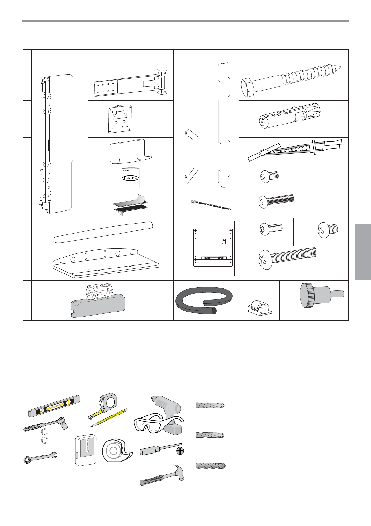
Components
AB C D
1x
1
2x 1x
4x
M8 x 80mm
1x
2
1x
3
4
5
1x
6
2x
4x
1x
4x
1x
WALL MOUNTING TEMPLATE
4x
4x
10x
2x
4x
M8
M4 x 8mm
M4 x 22mm
M4 x 12mm
10x
ENGLISH
M6 x 8mm
1x
7
1x
8
Tools Needed
13mm
1/2”
4x
1/4-20 x 1.5”
2x
4x
1x
M4 x 10mm
HOLLOW WALL
Ø 1/2” (13 mm)
2
1
WOOD
Ø 7.32" (5.5 mm)
Ø 1/2" (13 mm)
1/2"
Stud Finder
888-61-042-G-01 rev. E • 08/16
CONCRETE
Ø 3/8" (9.5 mm)
3 of 15
Page 4
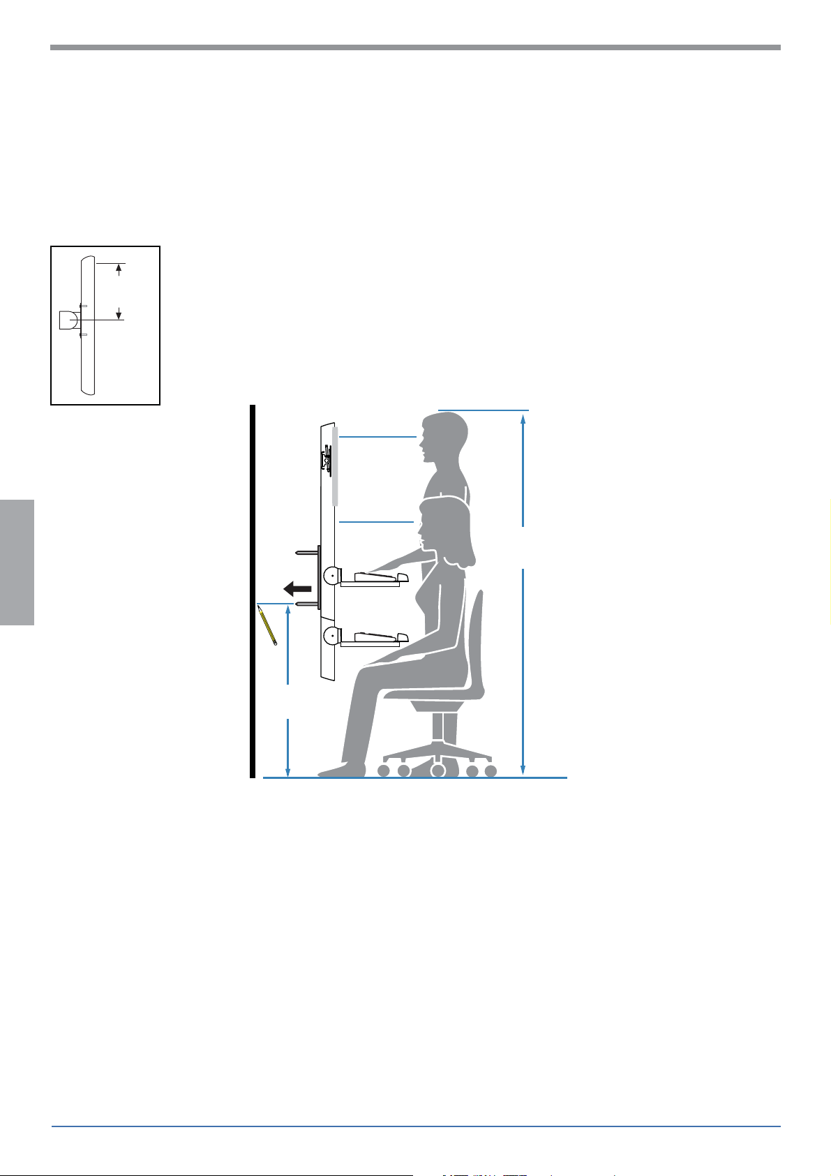
Mounting Height for Ergonomic Workstation
This mounting height is a recommendation for an ergonomic workstation that accommodates user heights of
5’10”-5’11” (178-180cm).
If user heights are di erent than this, you should change mounting height to accommodate user heights.
(Change mounting height one inch for every one inch di erence in user heights).
Mounting height assumes there is a 6” (152 mm) distance between the center of your monitor
mounting holes and the top of the screen. If your distance is smaller, you should increase mounting
6”
(152 mm)
height accordingly, if your distance is larger, you should decrease your mounting height accordingly.
ENGLISH
5’10” - 5’11”
(178-180cm)
42”
(1066mm)
4 of 15
888-61-042-G-01 rev. E • 08/15
Page 5
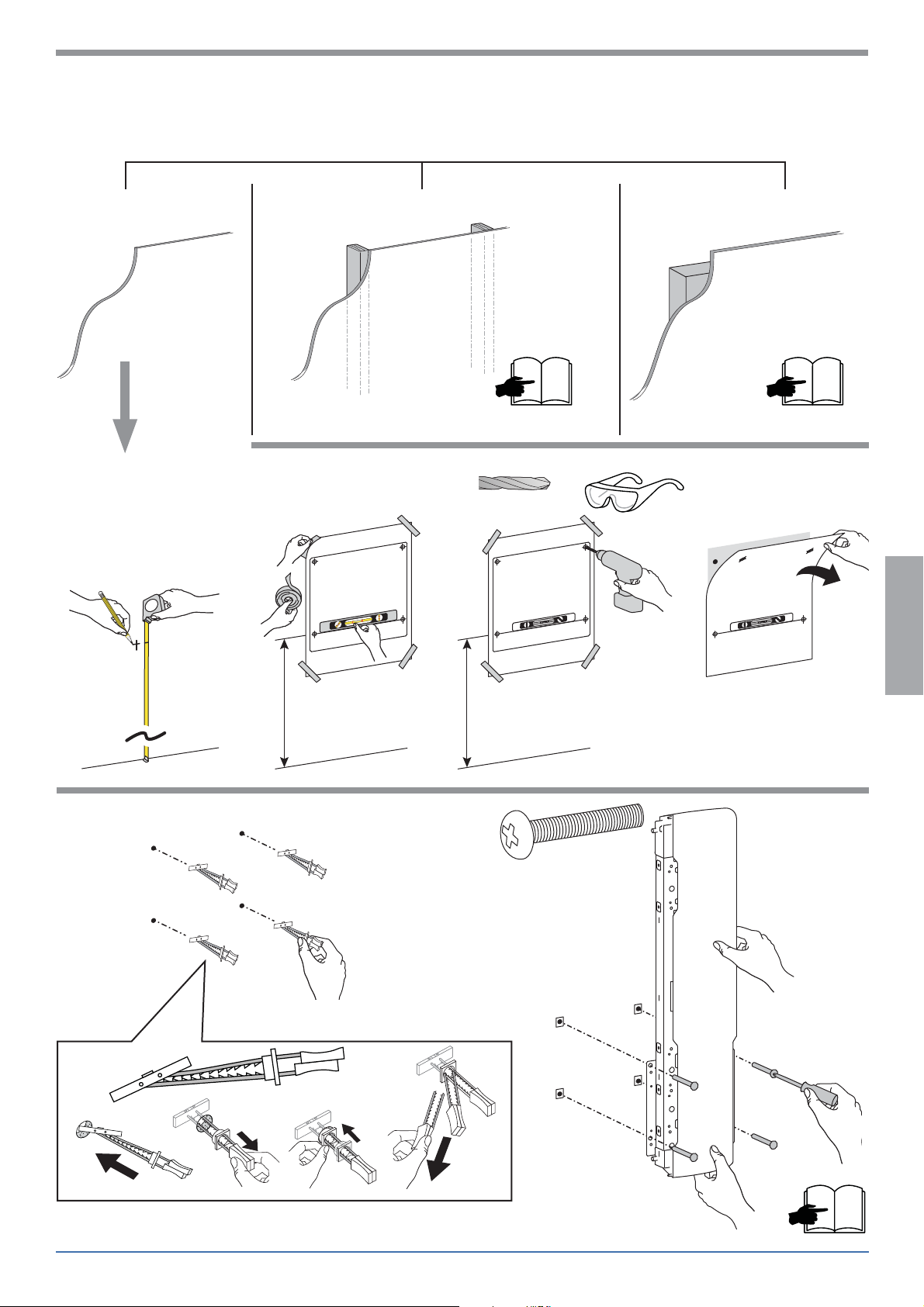
Set-up Steps
3 Mounting Options
Hollow Wall
abc d
1
WALL MOUNTING TEMPLATE
Wood Stud Concrete
Ø 1/2" (13 mm)
WALL MOUNTING TEMPLATE
76
ENGLISH
42”
(1066 mm)
2
a
4x
12 3 4
(1066 mm)
42”
(1066 mm)
b
42”
4x
1/4-20 x 1.5”
888-61-042-G-01 rev. E • 08/16
8
5 of 15
Page 6

Set-up Steps
Wood Stud
1
ENGLISH
bacde
WALL MOUNTING TEMPLATE
42”
(1066 mm)
42”
(1066 mm)
WALL MOUNTING TEMPLATE
7/32”
5.5mm
3-1/8”
80mm
Ø 1/2" (13 mm)Ø 7/32" (5.5 mm)
WALL MOUNTING TEMPLATE
2
a
2x
12 3 4
2x
13mm
b
2x
1/4-20 x 1.5”
6 of 15
M8 x 80mm
8
888-61-042-G-01 rev. E • 08/15
Page 7

Set-up Steps
Concrete
abc
1
42”
(1066 mm)
2
a
42”
(1066 mm)
WALL MOUNTING TEMPLATE
42”
(1066 mm)
b
Ø 3/8" (9.5 mm)
WALL MOUNTING TEMPLATE
e
4x
Mounting holes must be at least 3-1/8”
(80mm) deep and must be located within
solid concrete, not mortar or covering ma-
terial. If you drill into an area of concrete
that is not solid, reposition mounting
holes until both anchors can be fully
9.5-10mm
13mm
M8 x 80mm
WARNING:
inserted into solid concrete!
3/8”
3-1/8”
80mm
ENGLISH
c
d
WARNING:
Anchors that are not fully set in solid concrete
will not support the applied load resulting in
an unstable, unsafe condition which could lead
to personal injury and/or property damage.
Consult a construction professional if you have
any doubt about what this means in regard to
your particular situation.
8
888-61-042-G-01 rev. E • 08/16
7 of 15
Page 8

Set-up Steps
3
4
2x
M6 x 8mm
ab
4x
M6 x 8mm
ENGLISH
4x
M6 x 8mm
A B
< 10.8”
(274 mm)
A
< 18.4”
(467 mm)
8 of 15
B
888-61-042-G-01 rev. E • 08/15
Page 9

Set-up Steps
5
a
b
c
2x
M4 x 8mm
d
ENGLISH
e
2x
M4 x 8mm
4x
M4 x 12mm
888-61-042-G-01 rev. E • 08/16
9 of 15
Page 10

REMOVE STOP SCREW BEFORE USE.
f
CAUTION:
Product is shipped with a stop screw
that MUST be removed before use.
DO NOT REMOVE STOP SCREW BEFORE ATTACHING
KEYBOARD TRAY.
Failure too follow these instructions will cause
equipment damage.
ENGLISH
6
a
d
bc
4x
10 of 15
888-61-042-G-01 rev. E • 08/15
Page 11

Set-up Steps
7
8
4x
M4 x 8mm
4x
M4 x 10mm
ENGLISH
9
1
WARNING: The monitor will not be securely attached until the Locking Pin passes through the tab on the
Quick Release Bracket. Do not leave the monitor unsupported until you are certain the Locking Pin is in place.
888-61-042-G-01 rev. E • 08/16
2
34
11 of 15
Page 12

Set-up Steps
10
2x
ENGLISH
M4 x 22mm
Leave enough slack in cable to allow full
range of up-down motion.
11
2x
M4 x 8mm
12 of 15
888-61-042-G-01 rev. E • 08/15
Page 13

12
Important! You will need to adjust this product after installation is complete. Make sure all your equipment is
properly installed on the product before attempting adjustments. This product should move smoothly and easily
through the full range of motion and stay where you set it. If movements are too easy or di cult or if product does
not stay in desired positions, follow the adjustment instructions to create smooth and easy movements. Depending
on your product and the adjustment, it may take many turns to notice a di erence. Any time equipment is added
or removed from this product, resulting in a change in the weight of the mounted load, you should repeat these
adjustment steps to ensure safe and optimum operation.
Adjustment Step
a
13mm
b
ENGLISH
Increase Lift Strength
If the mounted weight is too heavy or this product does not stay up
when raised, then you'll need to increase Lift Strength:
Decrease Lift Strength
If the mounted weight is too light or this product does not stay
down when lowered, then you'll need to decrease Lift Strength:
888-61-042-G-01 rev. E • 08/16
13 of 15
Page 14

c
Adjustment Step
ENGLISH
d
1
2
1/2”
1/2"
Increase Friction
If this product moves too easily, then
you'll need to increase friction:
Decrease Friction
If this product is too diffi cult to move,
then you'll need to decrease friction:
3
14 of 15
888-61-042-G-01 rev. E • 08/15
Page 15

Set Your Workstation to Work For YOU!
Learn more about ergonomic computer use at:
www.computingcomfort.org
Height Position top of screen slightly below eye level.
Position keyboard at about elbow height with wrists fl at.
Distance Position screen an arm's length from face—at least 20” (508mm).
Position keyboard close enough to create a 90˚ angle in elbow.
Angle Tilt screen to eliminate glare.
Tilt the keyboard back 10° so that your wrists remain fl at.
To Reduce Fatigue
Breathe - Breathe deeply through your nose.
Blink - Blink often to avoid dry eyes.
Break • 2 to 3 minutes every 20 minutes
• 15 to 20 minutes every 2 hours.
For local customer care phone numbers visit: http://contact.ergotron.com
ENGLISH
888-61-042-G-01 rev. E • 08/16
15 of 15
 Loading...