

Ergosana Sana comfort 150 REHA, Sana comfort 250 REHA User Giude
Seat ergometer Sana comfort 150/250/REHA
User Guide
Article no.: 2.520064 rev.: b

Sana comfort 150 and 250 REHA
CE Conformity Declaration
ergosana GmbH herein declare that the products of the ergometer system Sana comfort 150/250/REHA
have been designed and manufactured in accordance with the relevant requirements of the EC directive
93/42/EEC.
This declaration loses its validity if the above devices are modified without ergosana‘s consent.
The medical products are checked by the notified body DEKRA and they bear the CE
mark CE 0124.
0124
Manufactured by:
ergosana GmbH
Truchtelfinger Str. 17
D-72475 Bitz
Harald Neukirchner
Quality manager
Article no.: 2.520064 rev.: b Page 2 of 24

Sana comfort 150 and 250 REHA
Table of Contents
1 General......................................................................................................4
1.1 Intended use ....................................................................................... 4
1.2 Contra-indication.................................................................................. 4
1.3 Features .............................................................................................4
1.4 Instruction ..........................................................................................4
1.5 Maintenance........................................................................................4
2 Product description ...................................................................................5
2.1 Unit Components.................................................................................. 5
2.2 Accessories..........................................................................................5
2.3 Potential equalisation............................................................................ 5
2.4 Technical data......................................................................................6
2.5 Signs and symbols................................................................................ 6
2.6 Safety notes........................................................................................7
2.7 Eliminating electromagnetic interferences ................................................ 7
3 Installation................................................................................................8
3.1 Location.............................................................................................. 8
3.2 Assembly instructions ........................................................................... 8
3.2.1 Unpacking and assembling ......................................................... 8
3.2.2 Seat adjustment ....................................................................... 8
3.2.3 Connecting the blood pressure cuff..............................................8
3.2.4 Mains connection.......................................................................8
4 Unit components .......................................................................................9
4.1 Control panel....................................................................................... 9
4.2 Rotational speed display on the control panel ........................................... 9
4.2.1 Panel interfaces for 250 ............................................................. 9
4.2.2 Keys and display..................................................................... 10
4.2.3 Setting the language ............................................................... 11
4.3 Blood pressure cuff for 250.................................................................. 11
5 Safety notes ............................................................................................12
5.1 Precautions during operation................................................................ 12
5.2 Safety precautions when operating with other devices ............................. 12
5.3 Maintenance safety precautions............................................................ 12
5.4 Interference ...................................................................................... 12
6 Start-up and initial preparation ...............................................................13
6.1 Blood pressure recorder for 250 ........................................................... 13
6.2 Applying the cuff for 250 ..................................................................... 13
7 Ergometry................................................................................................14
7.1 Defining the automatic load programs ................................................... 14
7.2 Recommended settings ....................................................................... 16
7.3 Remote operation............................................................................... 17
7.3.1 Explanation............................................................................ 17
7.3.2 Prerequisites .......................................................................... 17
7.4 Training program (option).................................................................... 18
7.4.1 Training with constant heart rate (Pulse-Steady-State)................. 18
7.4.2 Configuring a training program on the ergometer......................... 18
7.5 Rehabilitation version.......................................................................... 20
7.5.1 Additional control elements....................................................... 20
7.5.2 Options for the data transfer..................................................... 21
8 Maintenance and fault clearing................................................................22
8.1 Checking the measuring technology...................................................... 22
8.2 Cleaning the device ............................................................................ 22
8.3 Cleaning the blood pressure cuff for 250................................................ 22
8.4 Checking and setting the supply voltage................................................ 22
8.5 Changing a mains fuse........................................................................ 23
8.6 Disposal information........................................................................... 23
9 Appendix .................................................................................................24
9.1 Technical Customer Service and Sales Locations ..................................... 24
Article no.: 2.520064 rev.: b Page 3 of 24

Sana comfort 150 and 250 REHA
1 General
The Sana comfort 15/ 250/REHAa seat ergometers are high-performance, state-of-the-art ergometers.
Sana comfort 250 is equipped with a blood pressure measurement module, located in the ergometer's
control console.
The devices meet the highest quality standards for accurate physical exertion tests to conduct measurements in cardiovascular and pulmonary function diagnostics. Thanks to the comfortable seat and the special sitting position allowing comfortable pedalling, this ergometer is suitable for long-term training as
well as adipose patients.
1.1 Intended use
Ergometer Sana bikes are bicycle ergometers that are intended for defined exercise ergometry during a
patient's examination and therapy. These products are used in practices, clinics, therapy and rehabilitation centres. The ergometers are operated by physicians and medical personnel.
1.2 Contra-indication
In the event of the following contra-indications, NO exercise test must be performed:
in the case of acute cardiac infarction or unstable angina pectoris, serious hypertonia at rest, carditis,
insufficiency of the heart, serious valvular heart defect, serious cardiac arrhythmia at rest, aortic aneurysm or other manifest cardiovascular diseases.
1.3 Features
The following characteristics make the unit exceptional:
• Attractive design
• Comfortable mounting and dismounting
• Stable steel construction, compact drive unit
• Stable clamps on saddle and handle bars
• Impact- and scratch-resistant casing, easy to clean
• New, high-performance control electronics
• Graphic display featuring visual representation of ergometry data
• Easy operation via menu mode
• Remote operation – personalised programs – training programs
• Disturbance-free blood pressure measurement
• Performance range from 1 to 999 watts
• Guaranteed accuracy (error factor < 3% in the independent rpm range)
• Nearly noiseless drive unit
• Pleasant pedalling sensation due to large gyrating mass
• Galvanically isolated RS 232 interface, secure data transfer
• Reha version with USB bus
• Reha version with ECG amplifier and suction electrode system
1.4 Instruction
Before the initial operation, carefully read through this user guide, paying special attention to the warnings and safety instructions.
1.5 Maintenance
This is a low-maintenance device. You will find detailed maintenance instructions in section 8.
Article no.: 2.520064 rev.: b Page 4 of 24
Sana comfort 150 and 250 REHA
2 Product description
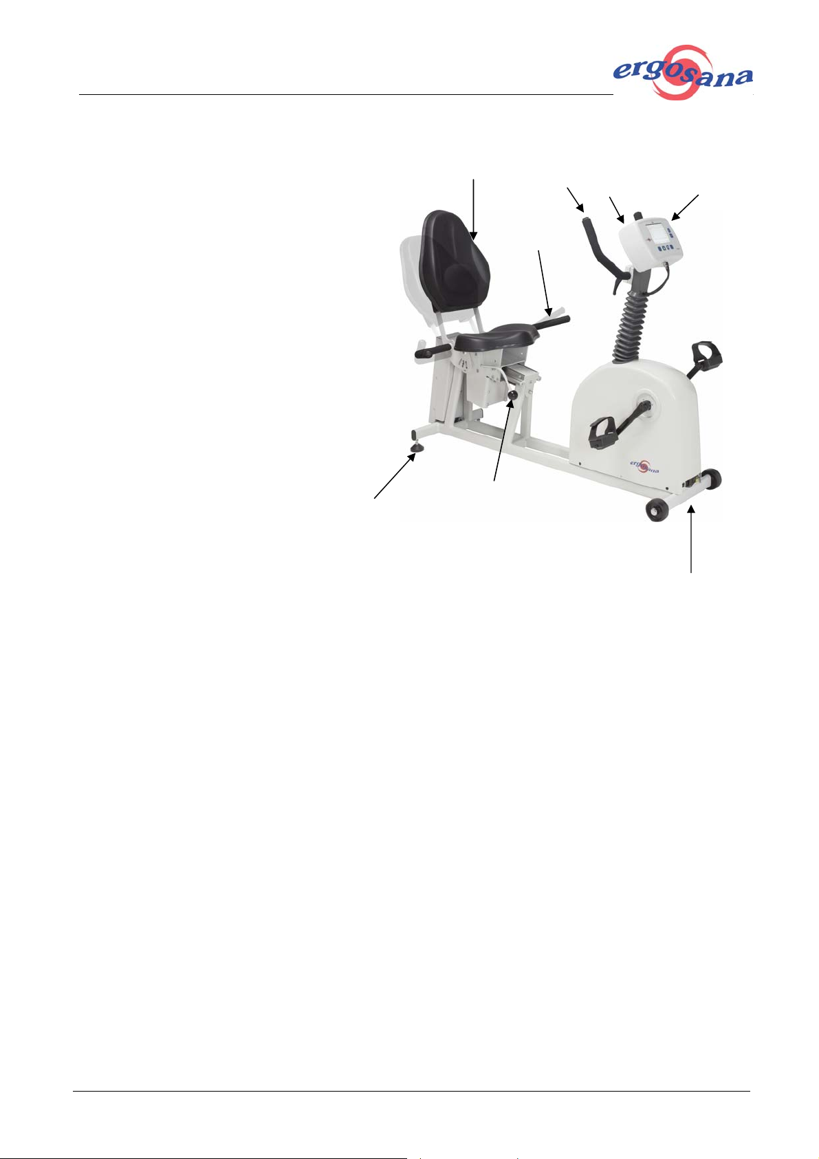
2.1 Unit Components
1. Handlebar
2. Control console
3. Locking lever to adjust the back rest
4. Handlebar on the seat
5. Arrow keys for horizontal seat adjustment
6. Back rest
7. Base adjuster for height adjustment
8. Mains connector, potential equalisation,
RS-232 interface
7
2.2 Accessories
6
1
5
2
4
3
Every device comes with:
Power cable with European plug
Blood pressure cuff for 250
User guide
Inspection report
8
2.3 Potential equalisation
A standard potential equalisation stud is located on the rear panel, next to the power connection unit. It
is marked with a green/yellow information sign. Using an earth cable, the ergometer can be connected
with the potential equalisation of the examining room, which serves as a common earth point for all other
mains-operated devices in the room to ensure that all devices have the same earth potential.
Article no.: 2.520064 rev.: b Page 5 of 24
Sana comfort 150 and 250 REHA
2.4 Technical data
Bicycle ergometer with blood pressure measurement in accordance with DIN 13405 /DIN VDE 0750-238.
Braking principle Computer-controlled brakes with permanent measurement of
torque. Braking performance is independent of revolutions per minute.
Power range 1 to 999 watts
Load range independent rpm range 20 till 999 Watts
Range of revolutions 30 to 130 rpm for pedals
Load precision 3%, not less than 3 watts (in the independent rpm range)
Load parameters 1. In keeping with set internal load program
2. Parameters from external master unit over interface, in 1 watt
steps.
3. Manual in 5-watt and 25-watt steps
Load software 5 freely programmable ergometry programs
1 automatically controlled pulse-steady-state program
Time intervals 1 min to 99 min
Display Graphic LCD with 320 x 240 pixels, CCFT background lighting
Blood pressure measure-
ment for 250
Pulse measurement With a blood pressure unit or an optional Polar pulse monitoring
Horizontal seat adjustment Continuously variable on a slope, special seat for heights between
Maximal permissible
patient weight
Long-term accuracy Torque equalisation at any time with weight
Power supply 230 VAC 50–60 Hz, 115 VAC 50–60 Hz
Electric inputs/outputs RS-232 (galvanically isolated)
Base dimensions 40 x 130 cm
Weight 74 kg
Indirectly, with a specific, modified measuring system based on R-R,
and computer analysis including maximal suppression of artefacts
during ergometry. Automatic deflation rate of 3 mmHg/pulse. Measuring range 40 - 300 mmHg.
system; pulse rate 35 - 240
150 and 210 cm, electric drive.
250 kg
The unit is suitable for use in networks according to CISPR 11,
group 1, class B.
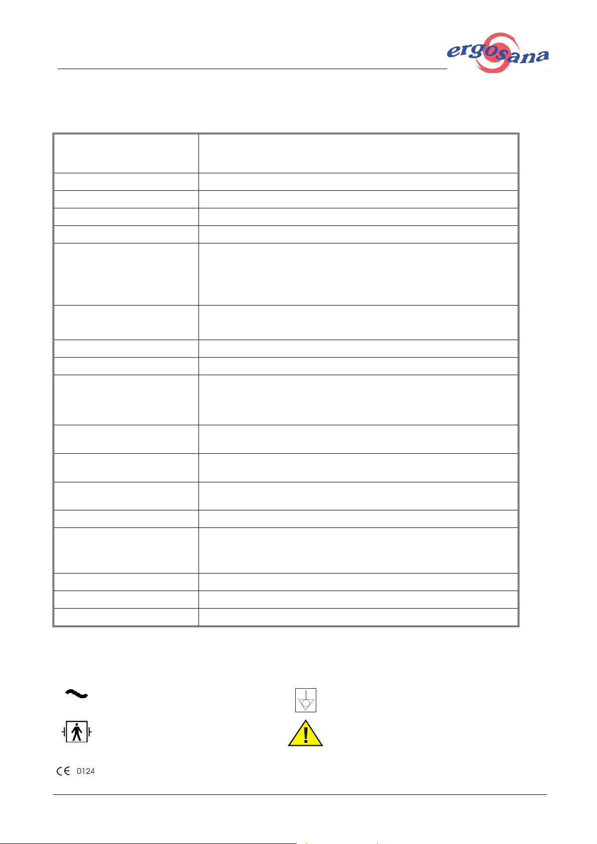
2.5 Signs and symbols
In this section, the signs and symbols used in connection with this device are explained:
Mains operated, alternating current
BF classified component
93/42/EEC for medical products 0124
DEKRA
Article no.: 2.520064 rev.: b Page 6 of 24
IPX0
Potential equalisation connection (earth)
Warning! Follow the instructions in the documentation.
Protection class of the casing: IPX0
Sana comfort 150 and 250 REHA
2.6 Safety notes
Safety precautions when operating with other devices
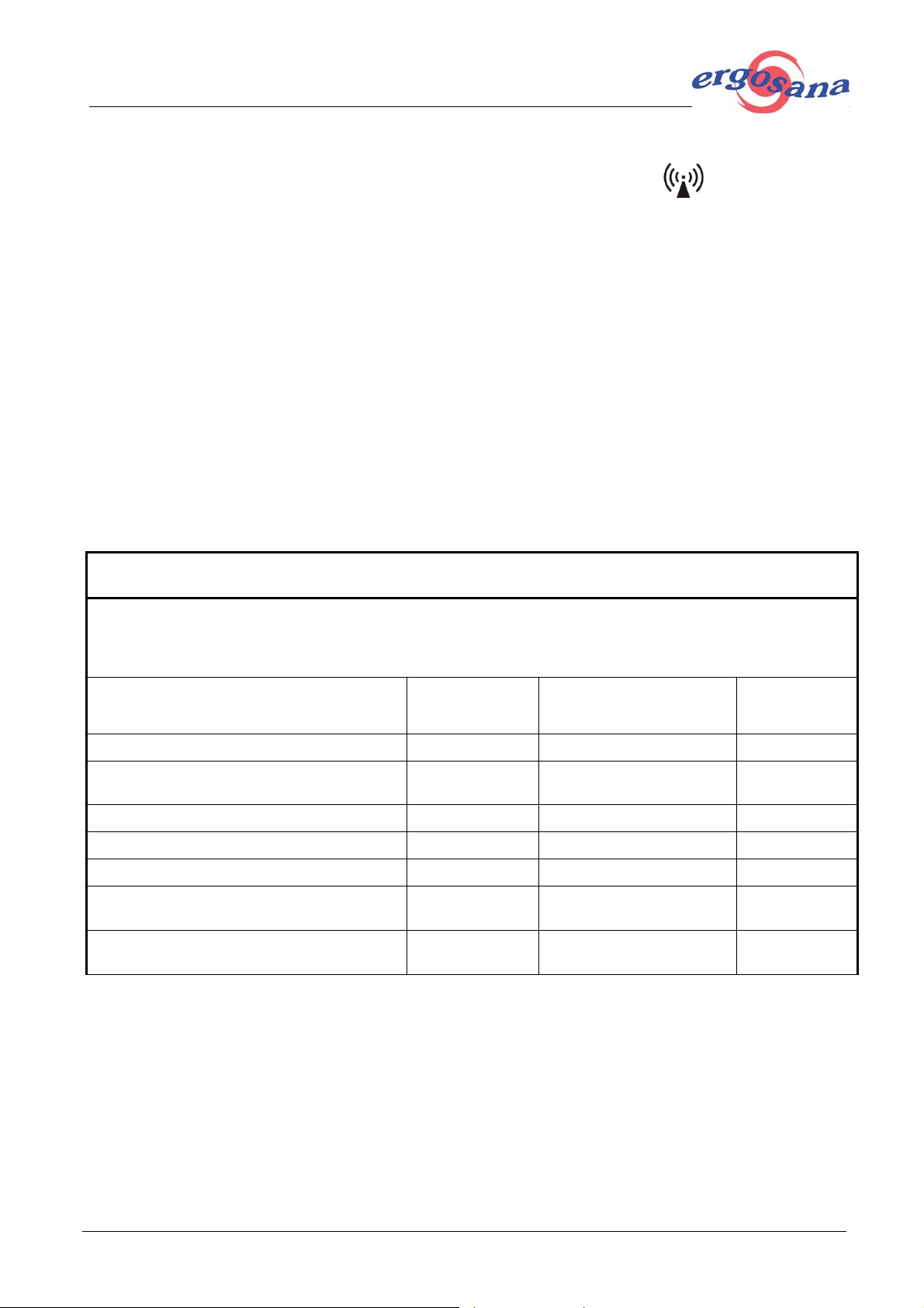
Portable communication devices, HF radios and devices labelled with the symbol (non-ionic electromagnetic radiation) can affect the operation of this device (see section 2.7).
2.7 Eliminating electromagnetic interferences
1. The unit is only designed for operation in the following electromagnetic environment: Radio frequency emission according to CISPR 11, group 1, class B.
2. Group 1 means that the ergometer exclusively uses HF energy for its internal function. The HF emission is therefore very low and unlikely to disturb electronic devices in the vicinity.
3. Class B means that the ergometer is suitable for use in any facilities including residential areas, even
if it is directly connected to the public mains that also supplies residential buildings.
4. The general electromagnetic environment with regard to the device's electromagnetic immunity is
defined as follows: the voltage corresponds to the typical business or hospital environment, and the
humidity is at least 30%, especially if the floors are synthetic.
5. If disorders should nevertheless occur, especially in the vicinity of devices labelled with the symbol
"non-ionic electromagnetic radiation", check the recommended minimal distance according to the following table. More information is given in the service manual.
Recommended safety distances between portable and mobile HF telecommunication device s and
the ergometer
The ergometer is designed for operation in an electromagnetic environment with controlled HF disturbance.
The user can help avoid electromagnetic interferences by keeping the minimum distance between portable
and mobile HF telecommunication devices (senders) and the ergometer, depending on the output performance of the communication device a s ind icated below.
HF source Rate
[MHz]
Microcellular phone CT1+, CT2, CT3 885–887 MHz 0,01 0,23
Cordless DECT telephone, WL AN, UM T S mo-
bile phone
Mobile pho n e, U S A 850/1900 1,2 1.8
Mobile pho n e, G S M8 5 0 , NMT 9 0 0 , D C S 1 80 0 850/900/1800 1 2.3
Mobile pho n e, G S M 90 0 900 2 3.3
Walkie-talkie (rescue services , po lice, fire
brigade, maintenance serv ices )
Mobile radio system (rescue se rv ices , police ,
fire brigade)
1880-2500 0.25 1.17
81-470 5 2.6
81-470 100 11.7
Rated power P of the
sender [W]
Distance
[m]
Article no.: 2.520064 rev.: b Page 7 of 24

Sana comfort 150 and 250 REHA
3 Installation
3.1 Location
Install the device in a suitable position (refer to safety instructions in section 5).
The unit should not be stored or operated in wet, moist or dusty surroundings. Nor should the unit be
exposed to direct sunlight or other sources of warmth.
The unit should not come into contact with acidic vapours or fluids.
The unit should not be placed near X-ray units, large transformers or electrical motors. There must be a
distance of at least one meter between the unit and the mains network.
3.2 Assembly instructions
3.2.1 Unpacking and assembling
Install the control panel after unpacking the unit. In order to do so, insert the two tabs on the back of the
control panel into the handle bar pipe and press them downward to their stop. The operator's side should
usually face the front so that the display can be seen by the person operating the machine. Connect the
potential equalisation cable to the flat plug at the back of the control panel.
Connect the main plug with the connecting socket. Fasten the rear cover with 4 screws.
Remove the seat's transport protection.
With the help of the base adjustor on the rear lower side of the ergometer, adjust the device so that it is
flush with the floor. The ergometer is then fully stabilised.
3.2.2 Seat adjustment
Mechanical seat adjustment
The seat is infinitely variable horizontally in order to accurately adjust the distance to the pedals. The
seat can be adjusted for persons between 150 cm and 210 cm in height. The handle next to the control
console ensures safe grip while positioning the feet on the pedals.
A ball-grip lever is used to adjust the sitting position. This lever is located on the right hand side, underneath the seat, and is easily accessible. Press the ball handle downwards to unlock the seat break, and
adjust the seat until the correct sitting position has been found. Pull the lever upwards as far as it will go
to lock the seat.
The seat construction is designed for patients weighing up to 250 kg.
Motorised seat adjustment
Adjust the seat by use of the arrow buttons.
3.2.3 Connecting the blood pressure cuff
The interfaces for the air tube and the microphone are located underneath the seat's guiding rail. Connect the blood pressure cuff by screwing the hose connection onto the joining nipple and inserting the
microphone plug in the socket next to it.
3.2.4 Mains connection
Establish potential equalisation (see section 2.3) and plug the supplied power cable into an earthed
socket. As the device is preset to the local mains voltage (refer to section 8.4), you can switch it on using
the main switch at the front.
Article no.: 2.520064 rev.: b Page 8 of 24
 Loading...