

ErgoPack 700X, 713X, 745X, 726X Original Operating Instructions

EN
For ErgoPack 700X/713X/726X/745X
serial no.___________________
Original Operating Instructions
V9

Declaration of conformity
EU declaration of conformity
(for the purposes of the EU machine directive 2006/42/EG)
We, ErgoPack Deutschland GmbH
Hanns-Martin-Schleyer Str. 21
89415 Lauingen
hereby declare, that the Ergonomic Pallet Strapping Systems type "ErgoPack 700X, 713X, 726X, 745X“,
to which this declaration refers, complies with the respective relevant and basic health and safety
requirements of the EU directives because of their concept, type of construction and the model we
have brought on to the market.
This declaration loses its validity if a change is made to the system without our permission.
Respective
EU directives: EU Machine directive (2006/42/EG)
EU Guideline on electromagnetic compatibility
(2014/30/EU)
Applied standards EN 12100: 2010
EN 415-8: 2016
EN 61000-6-2:2005
EN 55011: 2018-05
EN 60 204-1: 2006
Since strapping system: 0319GTQLR/10050
Since year of manufacture: 2019
Lauingen, 14th of June, 2018
______________________
Andreas Kimmerle
CEO
Authorised representative for publishing technical documentation:
ErgoPack Deutschland GmbH
Hanns-Martin-Schleyer-Str. 21
89415 Lauingen
-2-

Table of contents
1. Validity of the operating instructions 5
2. General 6
2.1 Moving the strapping system 6
2.2 Parking the strapping system 6
2.3 Work area space requirements 7
2.4 Environmental conditions 7
2.5 Energy supply charger/battery 8
2.6 Notes on environmental protection 9
2.7 Meaning of warning symbols, usage conventions 10
3. Recommendations for protective measures 11
3.1 Safety regulations for battery and charger 12
4. Description 13
4.1 Construction 13
4.2 Operating panel strapping unit 14
4.3 Touch display strapping unit 14
4.4 Touch display sealing head 15
4.5 Indication and commissioning of the 36V charger 16-17
5. Technical data 18
5.1 Strapping unit 18-19
5.2 Sealing head 19-20
6. Intended use 21
7. Commissioning 22
7.1 Battery charger 22
7.2 Charging the battery 22-25
7.3 Setting strap width at the sealing head 26
7.4 Switching on the strapping system 27
7.5 Setting strap tension range at the sealing head 28
7.6 Setting tension force at the sealing head 29-30
7.7 Setting mode of operation at the sealing head 31-32
7.8 Select favorite 32
-3-

7. 9 Setting welding time 33
7.10 Changing strap coil 34-42
7.11 Setting pallet width 43
8. Operation 44
8.1 Strapping 44-48
8.2 Tensioning and sealing of pallets above 70cm height 49-52
8.3 Sealing control 53
8.4 Tensioning and sealing of pallets below 70cm height 54-56
9. Risks 57-59
10. Service and repair 60
10.1 Cleaning the ChainLance 60
10.2 Replacing the ChainLance 61-65
10.3 Replacing the reversing sledge ´ 66-68
10.4 Replacing individual chain links 69
10.5 Replacing the length adjusting belt 70-71
10.6 Changing the sealing head 72-73
10.7 Changing the control box joystick unit 74-76
10.8 Changing the control box display unit 77-78
10.9 Changing the motor 79-81
10.10 Cleaning/replacing the tension wheel at the sealing head 82-83
10.11 Cleaning/replacing the tooth plate at the sealing head 83
10.12 Replacing the cutter at the sealing head 84
11. Software updates 85-87
12. Spare parts list 88
13. Personal protective equipment 89
14. General safety warnings for power tools 90-93
-4-

1. Validity of the operating instructions
The operation in these instructions is explained by using the
ErgoPack 726X as an example.
All points in these instructions referring to the operation of the
sealing head are not applicable as far as the “ErgoPack 700X” is
concerned.
These operating instructions are valid for the following models:
ErgoPack 700X
Strapping system with electrical drive, electronically controlled via
joystick, without sealing head
ErgoPack 713X
Strapping system with electrical drive, electronically controlled via
joystick, with a sealing head for strap width of
9-13mm and a maximum tension force of 1200N
ErgoPack 726X
Strapping system with electrical drive, electronically controlled via
joystick, with a sealing head for strap width of
12-16mm and a maximum tension force of 2500N
ErgoPack 745X
Strapping system with electrical drive, electronically controlled via
joystick, with a sealing head for strap width of
15-19mm and a maximum tension force of 4500N
-5-
2. General
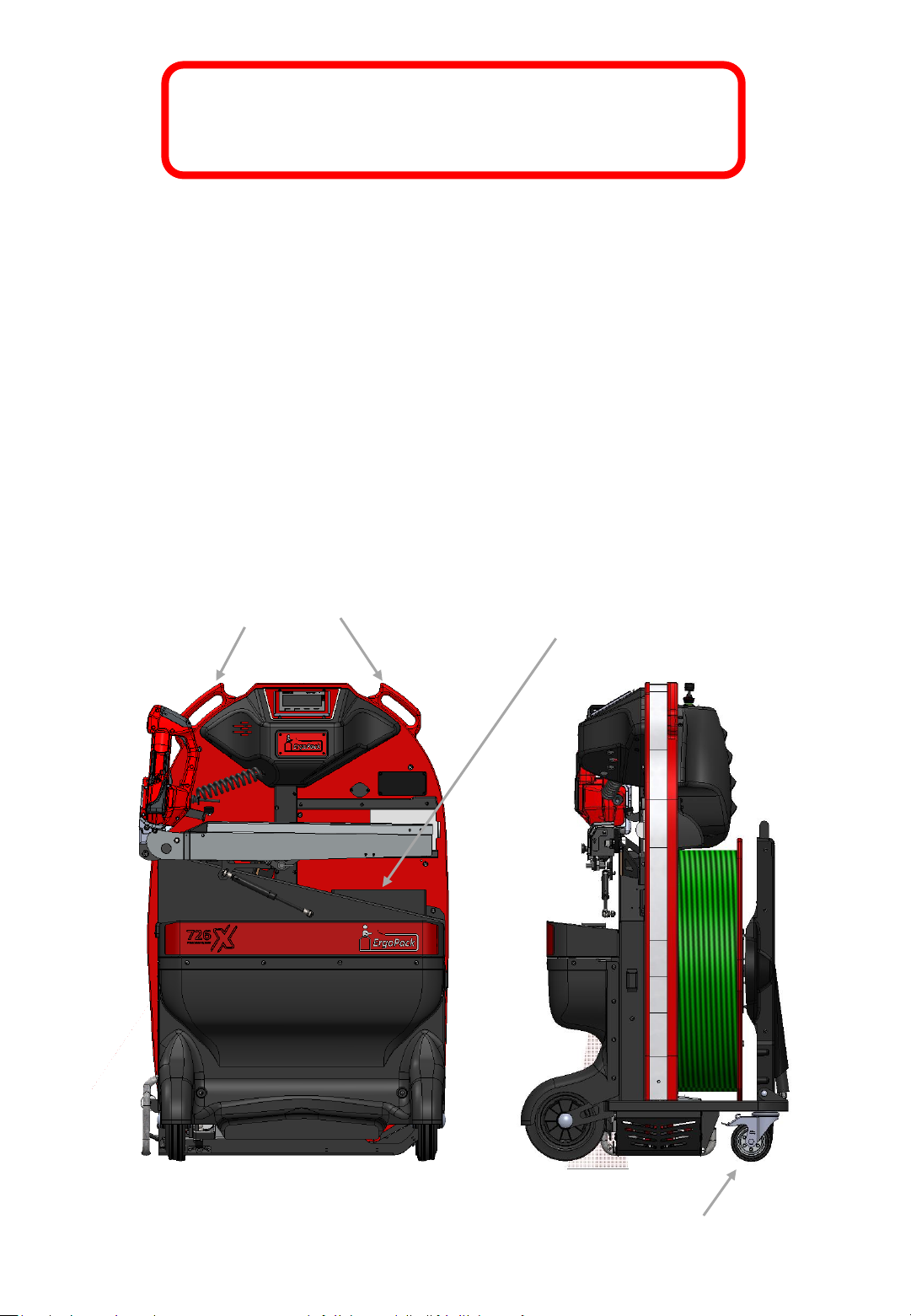
2.1 Moving the strapping system
The strapping system can be pushed in an upright position with the two hand
grips (Fig.1). For pushing it you must release the brakes of the two guide rolls
on the strap side (Fig.1a).
2.2 Parking the strapping system
After having parked the strapping system you have to lock up the brakes of
the two guide rolls (Fig.1a) on the strap side to avoid that the system is rolling
away accidentally.
Handles
Operating instructions
Fig. 1
Fig. 1a
Guide roll with
parking brake
-6-
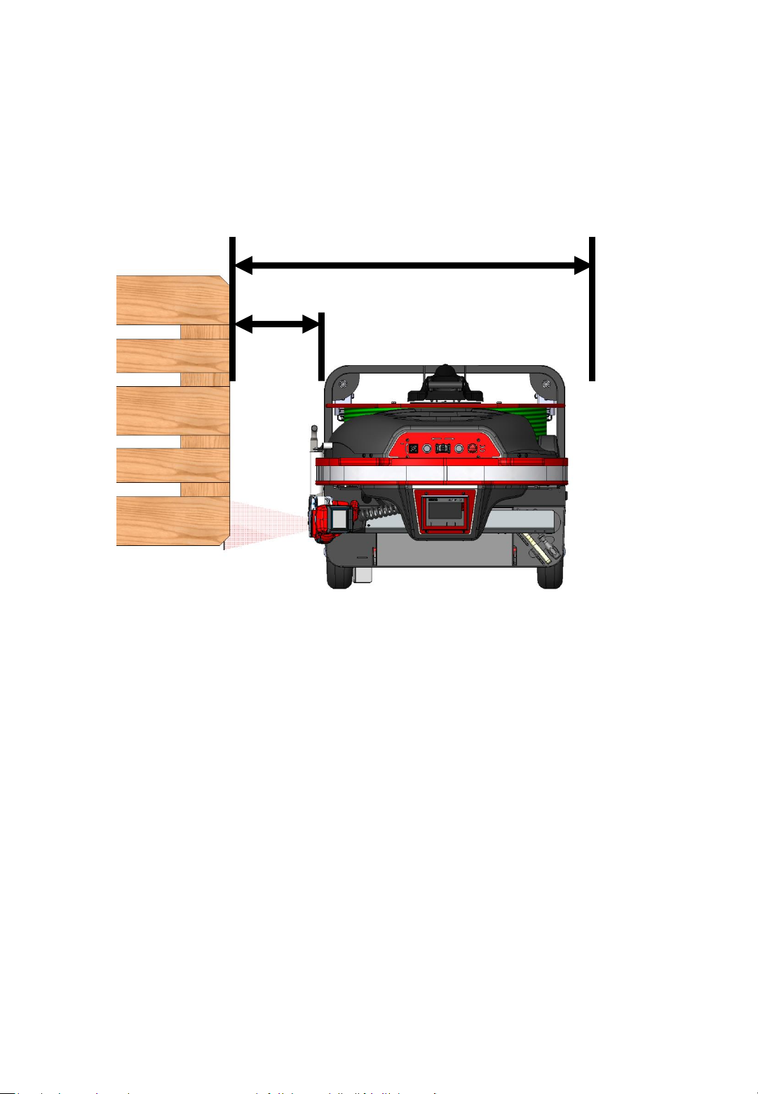
2.3 Work area space requirement
For a safe operation while strapping, the system has to be positioned correctly
in front of the pallet. Therefore, a free area of at least 1,10 m width in front of
the pallet to be strapped is required.
1,10 m
0,30 m
Fig. 2
2.4 Environmental conditions
The strapping system is only to be used in a covered dry area, otherwise the
risk of an electric shock can not be ruled out.
The ambient temperature during operation must not exceed 50°C and not fall
below 0°C.
For the strapping system, an electrically conductive floor is recommended.
-7-

2.5 Energy supply charger/battery
Charger 3 stage charger
Prim.: 198-264 VAC 50/60 Hz max. 2,0A
Sec.: 44,5V DC/4,5A
Max. power 200W
Battery pack 3 x 12V AGM battery
Weight: 19,5 kg
Charging time: approx. 10 hours
Operating temperature range: 5°C - 40°C
Number of strappings : Up to 650 standard strappings* per charge
Life span: approx. 300 - 500 charges
*standard strapping:
Battery pack: 100 charging and discharging cycles
Tape: 13mm PET (full strap coil)
Sealing head: 726X, tension force 900N without setting the SOFT tension
mode, welding time 2nd range
Pallet: pallet width 0,8 m, pallet height 1,15 m
Strapping speed: fast
Room temperature: 20°C
-8-
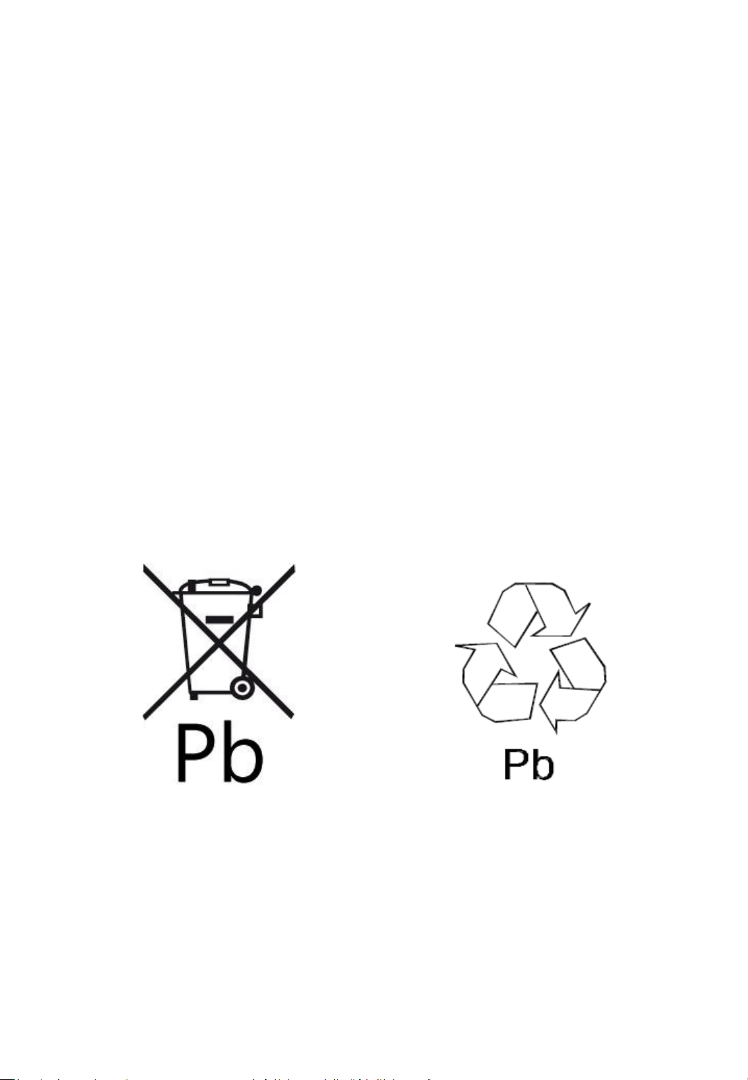
2.6 Notes on environmental protection
Physical or chemical materials injurious to health have not been used for
manufacturing the strapping system.
Concerning the waste disposal, valid national rules and regulations have to be
considered. Take care about disposing packaging, the product itself and parts
accordingly.
The specialist dealer offers disposal according to proper environmental
protection.
- Do not open the battery
- Do not throw the used battery into the domestic waste bin, into fire or
into water.
Fig. 3
-9-
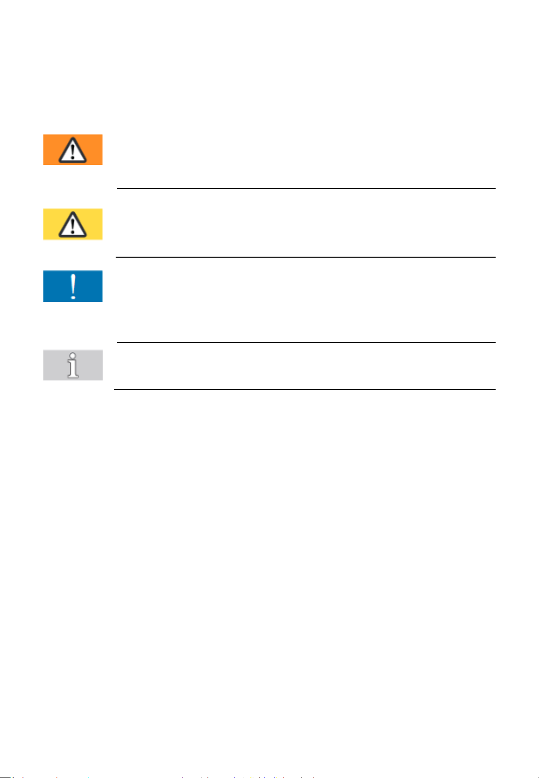
2.7 Meaning of warning symbols, usage
conventions
Warning!
Marks a hazard with moderate risk.
If not avoided, it can result in death or serious injury.
Caution!
Marks a hazard with a minor risk.
If not avoided, it can result in a minor or moderate injury.
Attention!
Marks a situation to be considered.
If not considered, it can lead to material damage or poor
operating results.
Note!
Marks useful, additional information.
-10-
3. Recommendations for protective measures
These operating instructions will help you to understand the strapping system
and how to use it according to regulations. The operating instructions contain
important notes on how to use the strapping system safely, properly and
economically.
Adhering to the notes helps you to avoid dangers, repairs and down times and
also increases the reliability and life span of the strapping system.
Note!
The operating instructions must be available at the place where the strapping
system is used (below the sliding window, see Fig. 1).
Before using the strapping system for the first time, the operating instructions
have to be read, understood and used by everybody who works with the
system. These works include operation, maintenance and repair!
See chapter 13 and chapter 14.
In addition to the operating instructions and the rules in the country and
place of use for the prevention of accidents, the recognized special rules for
working safely and according to proper and professional standards also have
to be respected.
In order to protect the strapping system against unauthorized access, it is
recommended to remove the key from the main switch and disconnect the
power supply from the battery pack.
The key should be kept safe from unauthorized access.
-11-

3.1 Safety regulations for battery and charger
• Check the plug and the cable before each use and have them replaced by
a specialist if they are damaged.
• The charger is intended only for the batteries supplied with the strapping
system. Do not charge any batteries from other manufacturers, use
original spare parts only.
• Protect the charger and battery against moisture; operate them in dry
rooms only.
• Do not open the battery and protect it from shock, heat and fire. Danger
of explosion!
• Store batteries in a dry frost-proof place. The ambient temperature must
not exceed 50°C and must not fall below -5°C.
• Damaged batteries may not be reused and must be disposed of properly.
Note!
• Keep the connection plug of the charger and the ErgoPack system away
from non-related objects and dirt.
• Plug and socket of battery, charger and power cable have a magnetic
connection. There is a risk that metallic particles, such as e.g. filing or
drilling chips or similar, adhere and may lead to damage of the contacts.
• Plug and socket should therefore be kept away from metallic particles and
regularly checked for the adhesion of such particles. For cleaning, it is best
to use compressed air in conjunction with a brush with synthetic bristles.
-12-

4.1 Design
4. Description
Fig. 5
Control panel
Safety cutter
Fig. 4
Strap brake
Control display
Fig. 7
Sealing head
Sliding window with safety switch
Operating instructions
Fig. 6
Tool-Lift
Covering of battery box
-13-
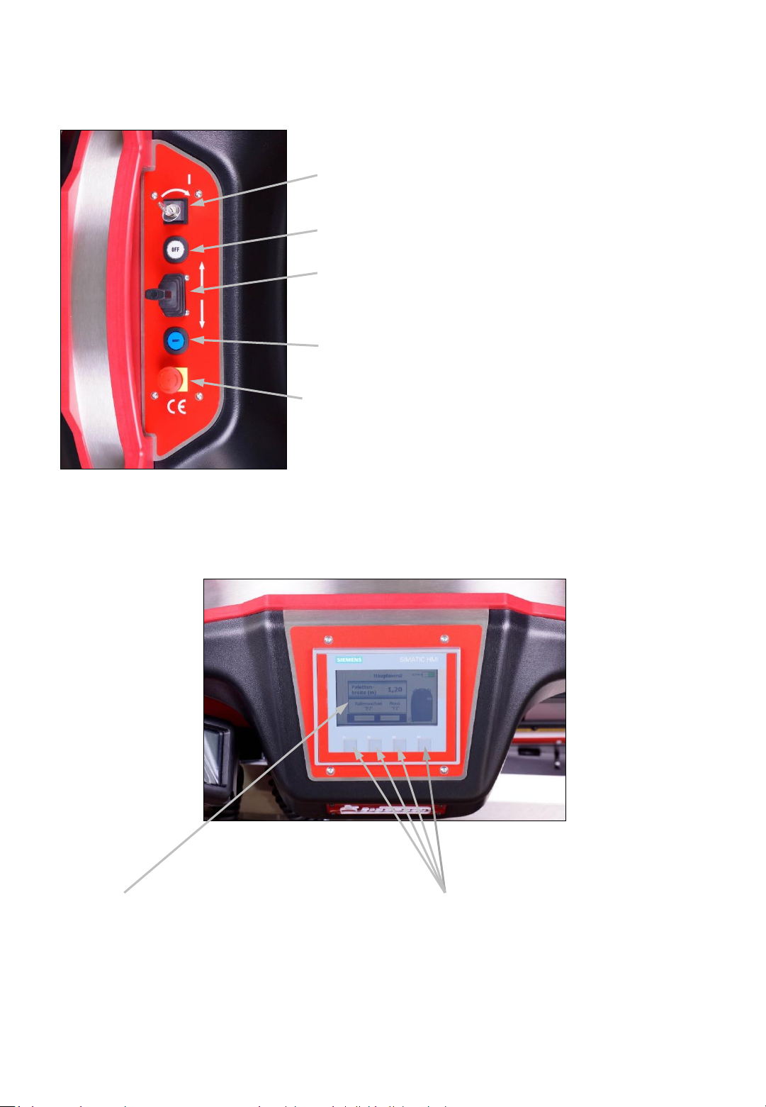
4.2 Control panel strapping system
Main switch (power supply 0/1)
OFF switch (disconnects the power supply)
Joystick (moving the ChainLance in and out with
precision speed control)
Reset switch (function check while switching on
and acknowledging of malfunctions)
EMERGENCY STOP switch (stops the strapping
system)
Fig. 8
4.3 Touch display strapping system
Fig. 9
Touch display for setting all parameters
at the strapping system, such as pallet
width.
Function key F1 – F4:
• F2 Strap coil changing mode
• F3 Menu
-14-
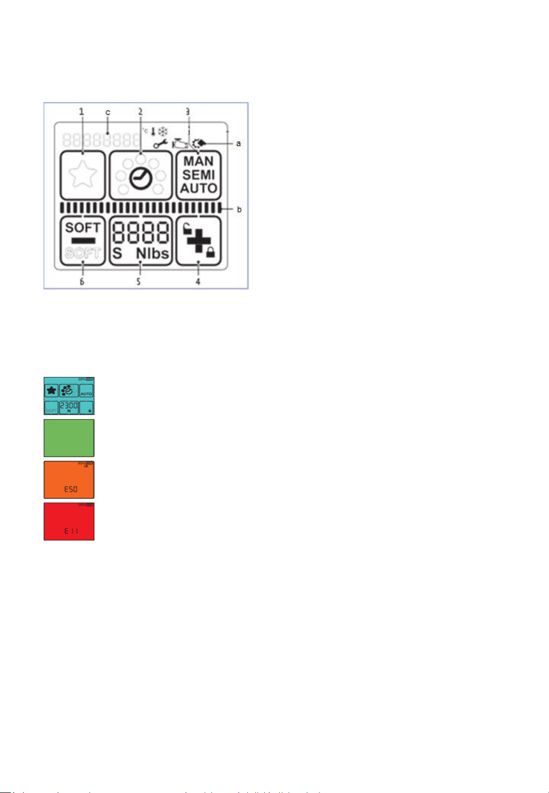
4.4 Control panel sealing head
1 „Favourite“
2 „Welding time“
3 „Operating mode“
4 „Plus & Keylock“
5 „Tension force“
6 „Minus & Soft tension“
a „Information symbols“
Fig. 10
b Status indicator bar „Tensioning/Welding“
c Display „Messages“
Display activated.
Welding process is finished, tool can be removed.
Application error: Temporary system error, can be rectified by the
operator.
Tool fault: static system error, rectify error. If the error cannot
be rectified -> ErgoPack service partner
-15-

4.5 Indication and commissioning of the
36V charger
Inside the red battery housing there are 3 x 12V AGM batteries installed and
connected in series. The ErgoPack 36V charger charges these batteries.
The green or yellow shining LED indication light on the 36V charger indicates
different operating states of the charger as well as the charging status of the
battery pack.
1.) Once the charger is plugged into the main power supply, the charging
process starts immediately, which will be indicated by a yellow shining LED
indication light, regardless of whether a battery pack is connected or not.
2.) You can now connect the battery pack to the charger. The charging process
starts again, thereby the yellow LED indication light remains yellow. The
batteries will be charged.
3.) As soon the LED indication light shines green, the charging process is
finished, the batteries are fully charged and the charger switches into
preserving mode. An overcharging of the batteries is not possible.
4.) By disconnecting the battery pack from the charger, the LED indication
light remains green and indicates then the operational readiness of the
charger.
5.) A new charging process starts when the battery pack will be connected
again, the LED indication light shines yellow again until the batteries are fully
charged and switches afterwards to green as well.
6.) As long as the charger remains plugged in the main power supply, the
steps described in point 5.) are performed. If the charger will be removed
from the main power supply and plugged in again, firstly the steps described
in point 1.) and afterwards the next steps will follow.
Do not remove the battery pack from the charger during the charging
process!
-16-

Attention!
The charging time is approx. 10 hours. The battery pack is only fully charged
when the LED indication light on the charger is permanently shining green!
LED indication
light
Automotive flat fuse
10A/32V
Fig. 11
-17-
5. Technical data
5.1 Strapping system
Dimensions (all types)
Length 665 mm
Width 770 mm
Height 1200 mm
Weight (without optional equipment):
ErgoPack 700X (incl. battery) 106 kg
ErgoPack 713X (incl. battery) 114 kg
ErgoPack 726X/745X (incl. battery) 115 kg
Maximum chain speeds:
Slow, strapping
Moving out horizontally: 27 m/min
Moving out vertically: 53 m/min
Moving in vertically: 52 m/min
Moving in horizontally: 39 m/min
Medium, strapping
Moving out horizontally: 29 m/min
Moving out vertically: 58 m/min
Moving in vertically: 57 m/min
Moving in horizontally: 45 m/min
Fast, strapping
Moving out horizontally: 66 m/min
Moving out vertically: 78 m/min
Moving in vertically: 76 m/min
Moving in horizontally: 65 m/min
Strap changing: setting up/threading in strap
Moving out: 10 m/min
Moving in: 8 m/min
Max. Chain thrust: 310 N
-18-

Plastic strap
Strap materials Polypropylene (PP)
Polyester (PET)
Strap width
713X, adjustable to 9-10 mm / 12-13 mm
726X, adjustable to 12-13 mm / 15-16 mm
745X, adjustable to 15-16 mm / 18-19 mm
Strap thickness
713X 0,40-0,80 mm (PET)
0,50-0,80 mm (PP)
726X 0,50-1,00 mm (PET/PP)
745X 0,80-1,30 mm (PET/PP)
5.2 Sealing head
Weight: 3,8 – 4,3 kg
(incl. spiral cable)
Dimensions length 335 mm
(incl. spiral cable) width 140 mm
height 180 mm
Tension
713X 150-1200 N
726X 400-2500 N
745X 400-4500 N
Tensioning speed 290 mm/s (713X)
220 mm/s (726X)
120 mm/s (745X)
Sealing friction-weld sealing
-19-

Measured A-graded
noise emission level
(EN ISO 11202) (EN 60745-1/2:2009)
713X LpA 79 dB (A) L
726X LpA 78 dB (A) L
745X LpA 79 dB (A) L
Sound power level, on average
(EN 60745 -1/2:2009)
713X LW
726X LW
745X LW
Aeq
88 dB (A)
Aeq
93 dB (A)
Aeq
92 dB (A)
Measurement inaccuracy K
713X 3,0 dB (A)
726X 3,0 dB (A)
745X 3,0 dB (A)
pAeq
77 dB (A)
pAeq
82 dB (A)
pAeq
81 dB (A)
Hand arm vibrations without using a Tool-lift
(EN 60745-1/2:2009)
713X a 2,4 ms
726X a 2,4 ms
745X a 2,3 ms
-2
-2
-2
Measurement inaccuracy K
713X 1,5 ms
726X 1,5 ms
745X 1,5 ms
-2
-2
-2
-20-

6. Intended use
This strapping system has been developed and constructed for an ergonomic
and safe strapping of pallets with plastic straps.
The strapping system is only to be used for strapping with plastic straps
(polypropylene and polyester). Strapping with steel strap is not possible with
this strapping system.
The strapping system is not designed to strap open and unpacked aliments.
The set tension force must correspond to the packaged goods to be strapped.
Constructing the strapping system there was not considered any risk due to
damaging of dangerous products or their package.
-21-

7. Commissioning
Attention!
Before using the strapping system for the first time, a visual inspection for
exterior damages has to be done.
7.1 Battery charger
The main voltage must comply with the details on the type plate.
The charger is only suitable for charging the delivered 36V battery pack.
7.2 Charging the battery pack
1.) Connect charger to the main voltage
2.) Open cover of battery case (by pulling at the outer corners
as shown below).
Fig. 12
-22-
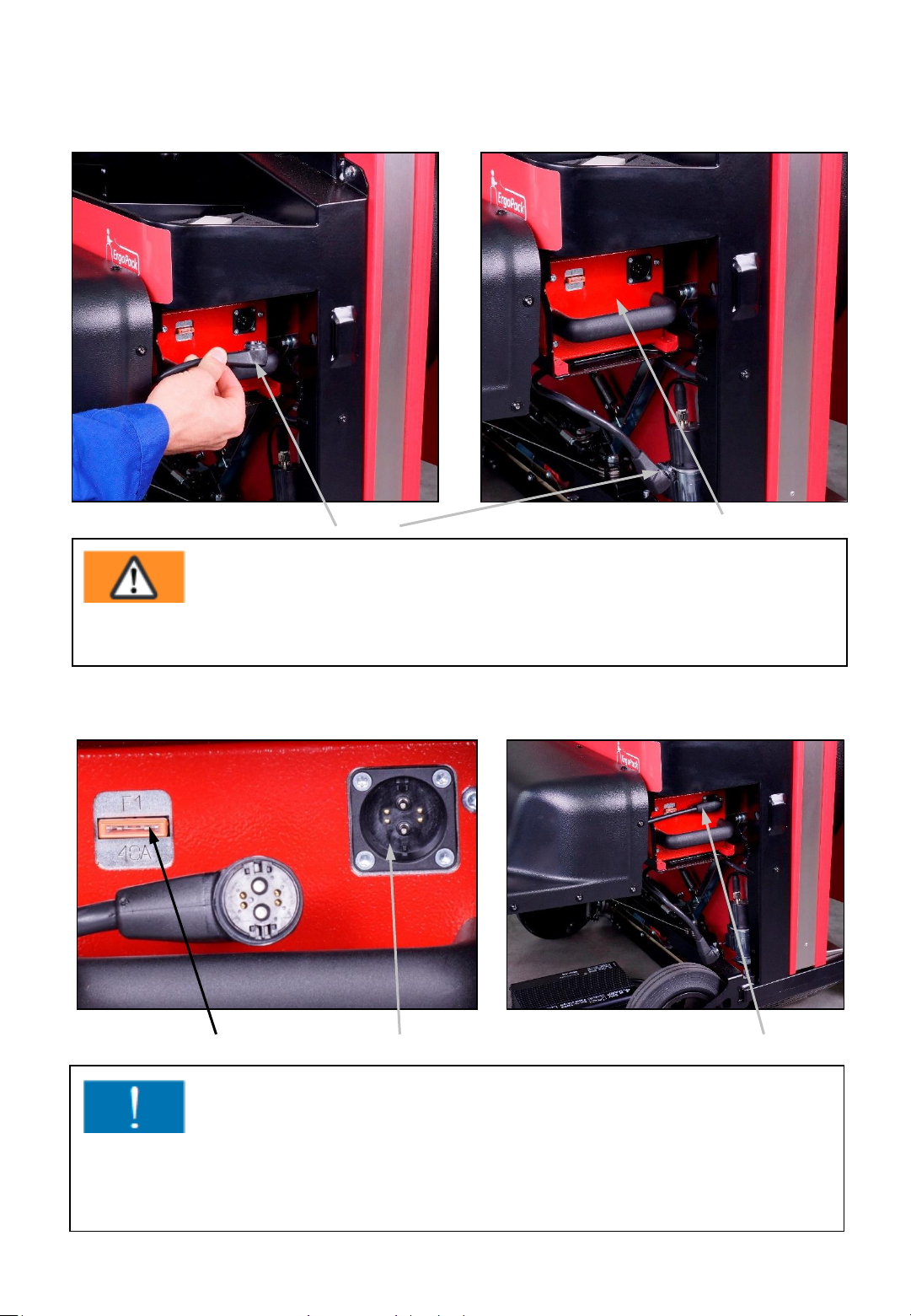
3.) Disconnect the plug (13a) from the battery pack (14a) and let the cable
hang freely down.
Fig. 13 Fig. 14
13a
14a
Warning!
Charge the battery pack only with the ErgoPack 36V charger through the
charging socket!
4.) Insert the plug of the 36V charger (16a) into the socket (15a) of the battery
pack.
Fig. 15
Fig. 16
15a 16a 15b
Attention!
Replace always defective flat fuses (15b) of the battery pack (see Fig.15) by a
new one of the same type (vehicle blade fuse 30A / 80V).
If necessary, contact your ErgoPack service partner.
-23-
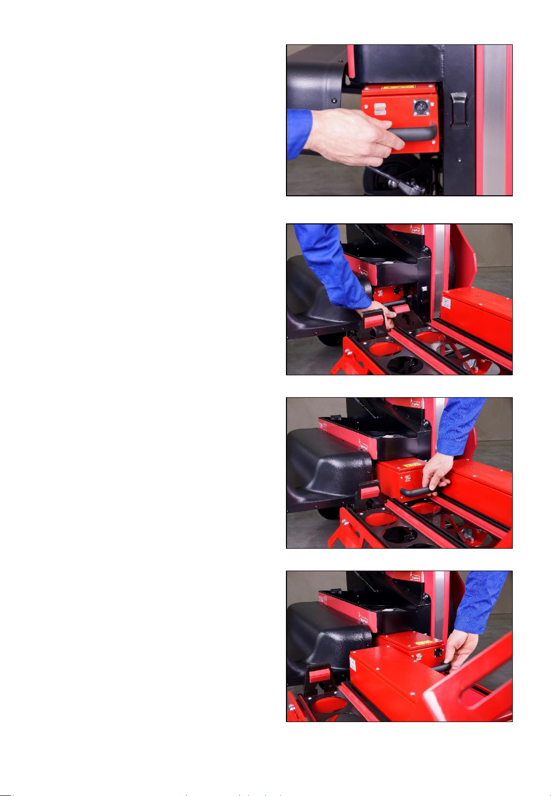
5.) Alternatively, the battery pack
can be also removed from the
strapping system ...
Fig. 17
… or be comfortably pulled out
to the battery trolley (optional
equipment)...
... and be replaced by a
previously charged battery pack.
Fig. 18
Fig. 19
-24-
Fig. 20
Attention!
The charging time is approximately 10 hours. The battery pack is only fully
charged when the LED indication light on the charger is permanently shining
green!
The maximum charging current flows if the temperature of the battery is
between 5°C and 40°C. Avoid battery temperatures below 0°C while charging.
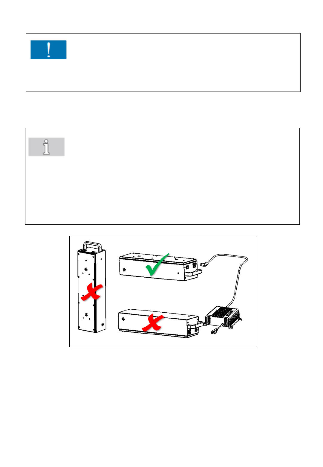
Note!
During charging, the battery pack always has to be in a horizontal position
(cover always upside). Never place the battery pack in lateral or upright
position.
You achieve the longest life span, if the battery pack is always charged
immediately after it was used and if it is only stored fully charged.
Fig. 21
-25-
7.3 Setting strap width at the sealing head
The sealing head can be used with different strap widths:
ErgoPack 713X 9-10 mm or 12-13 mm
ErgoPack 726X 12-13 mm or 15-16 mm
ErgoPack 745X 15-16 mm or 18-19 mm
The setting of the strap width is explained using the example of model 726X.
The setting of the strap width with the models 713X from 9-10 mm to 1213mm and 745X from 15-16mm to 18-19mm works accordingly.
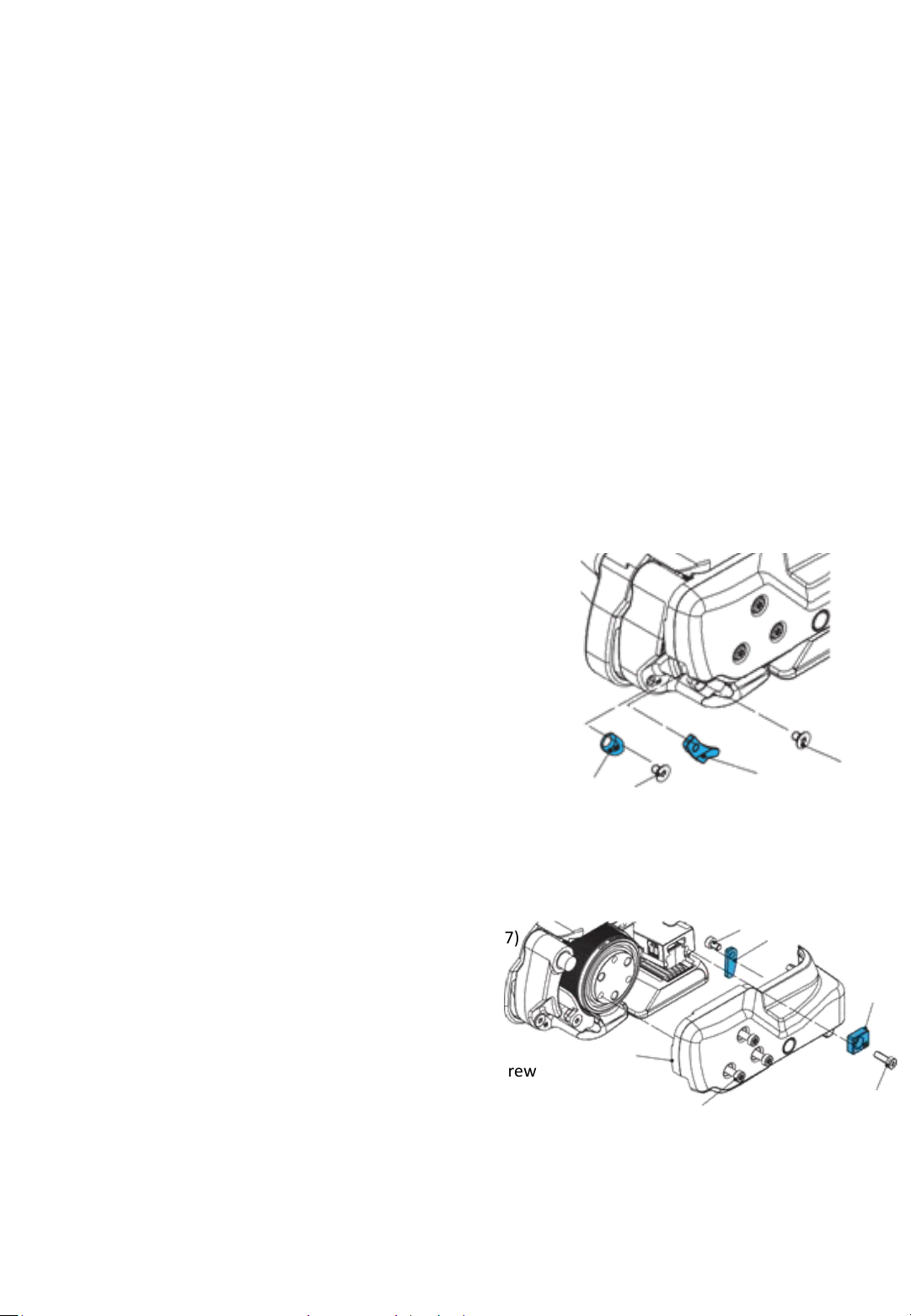
a) Change strap width from 12–13 mm to 15–16 mm
• Switch the strapping system off
• Release three cylinder screws Torx (6). Lift the rocker lever
towards the handle, release cylinder screw Torx (7) and
remove strap guide rear13mm (8).
• Remove side cover (5).
• Release counter-sunk screw Torx (2) and remove strap guide
front 13 mm (1).
• Release counter-sunk screw Torx (4) and remove strap guide
front 13 mm (3).
• Release cylinder screw Torx (10) and remove strap guide
rear 13 mm (9).
• Fit side cover (5) (secure cylinder screw with screw locking
varnish “medium-tight”. Install strap guide rear 16 mm (8).
b) Change strap width from 15-16mm to 12-13 mm
•Release three cylinder screws Torx (6). Lift the rocker
lever towards the handle, release cylinder screw Torx (7)
and remove trap guide rear 16 mm (8).
•Remove side cover (5).
•Fit strap guide front 13 mm (1) (secure counter-sunk
screw with screw locking varnish “medium-tight”).
•Fit strap guide front 13 mm (3) (secure counter-sunk screw
with screw locking varnish “medium-tight”).
•Fit strap guide rear 13 mm (9) (secure cylinder screw
with screw locking varnish “medium-tight”).
•Fit side cover (5) (secure cylinder screw with screw locking
varnish “medium-tight”). Install strap guide rear 13 mm (8).
1
2
Fig. 22
5
6
3
10
9
Fig. 23
4
8
7
-26-

7.4 Switching on the strapping system
Instructions:
Charge the battery pack as described under 7.2.
Plug in the connector of the power cable (24a) into the socket of the
battery pack (24b).
Close the cover of the battery case.
Make sure that the EMERGENCY STOP switch (25a) is not pressed. If
necessary, unlock it by turning.
Turn the main switch (25d) to the right to operating mode “1" and hold it
in this position for approximately 2 seconds.
Fig. 24 Fig. 25
24a 24b
25a
25b 25c
Follow the instructions on the display after the “ErgoPack” logo
disappeared (after approx. 45 seconds).
-27-
25d
7.5 Setting strap tension range at the sealing
head
Two strap tension ranges can be set at the sealing head:
NORMAL = Standard tension range for PET strap
713X = 400-1200 N
726X = 900-2500 N
745X = 1300-4500 N
SOFT = Soft tension range for PP strap
713X = 150-750 N
726X = 400-1360 N
745X = 400-1600 N
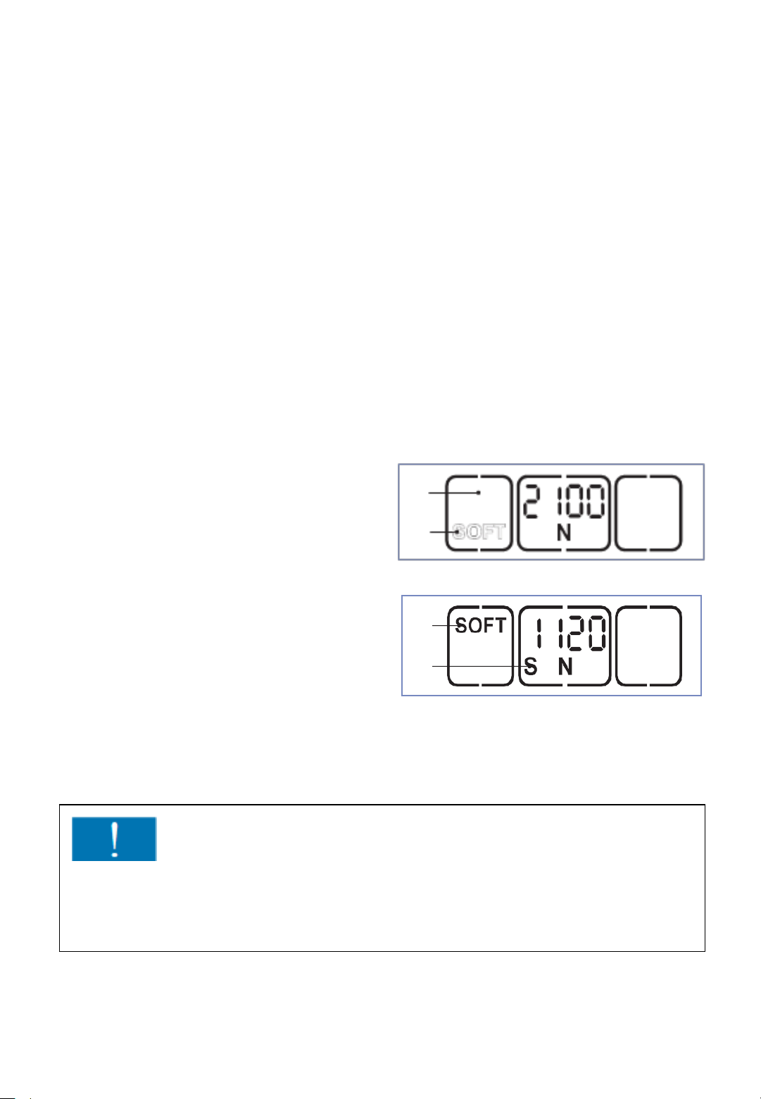
Press „Soft“ button (a).
The soft mode is deactivated when the
„SOFT“ display (b) changes position and
is shown outlined.
a
b
Press „Soft“ button (a).
The soft mode is activated when
the „SOFT“ display (c ) changes
position and is shown in bold.
The displayed tension force is
c
d
Fig. 26
reduced correspondingly.
On the left under the tension force
an "S" (d) also appears.
Attention!
Always use the SOFT tension mode when working with PP-strap!
By using the Soft mode, the tension wheel accelerates more slowly and avoids
excessive strap waste when sealing with PP strap.
-28-
 Loading...