

Page 1

EN
For ErgoPack
700/700E/713E/726E/745E
serial no.______________________
Original Operating Instructions
V3
Page 2

Declaration of conformity
EU declaration of conformity
for the purposes of the EU machine directive 2006/42/EG
ErgoPack Deutschland GmbH
Hanns-Martin-Schleyer-Str. 21
89415 Lauingen
We hereby declare that the strapping systems "ErgoPack 700, 700E, 713E, 726E, 745E",
to which this declaration refers complies with all the relevant and basic health and safety
requirements because of their concept, type of construction and the model we have
brought on to the market.
This declaration loses its validity if a change is made to the system without our permission.
Respective
EC directives: EC Machine directive (2006/42/EG)
EC Guideline on electromagnetic compatibility
(2014/30/EU)
Applied standards EN 12100: 2010
EN 415-8: 2008
EN 61000-6-2:2005
EN 55011: 2018-05
EN 60 204-1: 2006
Since strapping system: 0319XXXX/9000
Since year of manufacture: 2019
Lauingen, 03th May, 2018
______________________
Andreas Kimmerle
CEO
Authorised representative for publishing technical documentation:
ErgoPack Deutschland GmbH
Hanns-Martin-Schleyer Str. 21
89415 Lauingen
- 2 -
Page 3

Validity of the operating instructions
• The operation in these instructions is explained by using the
ErgoPack 726E as an example.
• As to ErgoPack 700, all the points in these instructions
referring to the operation of the sealing head and also all points
referring to the operation of the control box with the motor,
charger and rechargeable batteries are not applicable.
Also at all points in which the movement of the ChainLance is
described by using the joystick, at the ErgoPack 700 you
have to use the crank handle accordingly.
• All points in these instructions referring to the operation of
the sealing head are not applicable as far as the “ErgoPack
700E“ is concerned.
- 3 -
Page 4

These operating instructions are valid for the following models:
ErgoPack 700
Strapping system with manual drive via a hand crank,
without sealing head
ErgoPack 700E
Strapping system with electrical drive, electronically controlled via
a joystick, without a sealing head
ErgoPack 713E
Strapping system with electrical drive, electronically controlled via
a joystick, with a sealing head for strap width of
9-13 mm and a maximum tension of 1200 N
ErgoPack 726E
Strapping system with electrical drive, electronically controlled via
a joystick, with a sealing head for strap width of
12-16 mm and a maximum tension of 2500 N
ErgoPack 745E
Strapping system with electrical drive, electronically controlled via
a joystick with sealing head for strap width of
15-19 mm and a maximum tension of 4500 N
- 4 -
Page 5

Table of contents
Page
1 Technical data 6
1.1 Strapping system 6
1.2 Sealing head 7-8
1.3 Battery and charger 9
2 General 10-11
2.1 Notes on environmental protection 11
3 Safety regulations 12-15
3.1 Safety regulations for battery pack and charger 15
4 Description 16
4.1 Construction 16
4.2 Operating panel strapping system 17
4.3 Operating panel sealing head 17
4.4 Indications of the Dual-Charger 18
5 Commissioning 19
5.1 Battery charger 19
5.2 Charging the battery pack 19-21
6 Operation 22
6.1 Setting strap width at the sealing head 22
6.2 Switching on the control unit 23
6.3 Setting strap tension range at the sealing head 24
6.4 Setting strap tension at the sealing head 25
6.5 Setting mode of operation at the sealing head 26
6.6 Select favorite 27
6.7 Changing strap coil 28-41
6.8 Strapping 42-46
6.9 Tensioning and sealing pallets above 70 cm height 47-50
6.10 Sealing control 51
6.11 Setting welding time 52
6.12 Tensioning and sealing of pallets
below 70 cm height 52-54
7 Service and repair 55
7.1 Cleaning the ChainLance 55
7.2 Replacing the ChainLance 56
7.3 Replacing individual chain links 57
7.4 Replacing the reversing sledge 58-59
7.5 Replacing the length adjusting belt 60-61
- 5 -
Page 6
7.6 Changing the sealing head 62-63
7.7 Changing the control box with the motor 64-65
7.8 Cleaning/replacing the tension wheel at the sealing head 66
7.9 Cleaning/replacing the tooth plate at the sealing head 67
7.10 Replacing the cutter at the sealing head 68
8 Save moving and parking 69
9 Spare parts lists 69
10 General safety warnings for power tools 70-73
1. Technical Data
1.1 Strapping system
Weight:
ErgoPack 700 64,4 kg
ErgoPack 700E (incl. battery pack) 88,1 kg
ErgoPack 713E (incl. battery pack) 92,1 kg
ErgoPack 726E/745E (incl. battery pack) 92,9 kg
Dimensions (all types) Length 630 mm
Width 770 mm
Height 1200 mm
Maximum chain speeds
Mode A, strapping
Moving out horizontally: 40 m/min
Moving out vertically: 60 m/min
Moving in vertically: 44 m/min
Moving in horizontally: 54 m/min
Mode B: setting up/threading strap
Moving out 20 m/min
Moving in: 16 m/min
Max. chain thrust: 310 N
Measured A-graded
noise emission level L pa 79 dB (A)
(EN ISO 11202)
- 6 -
Page 7

1.2 Sealing head
Weight: 3,8 – 4,3 kg
(incl. spiral cable)
Dimensions length 335 mm
(incl. spiral cable) width 140 mm
height 180 mm
Tension
713E 150-1200 N
726E 400-2500 N
745E 400-4500 N
Tensioning speed 290 mm/s (713E)
220 mm/s (726E)
120 mm/s (745E)
Sealing friction welding
Measured A-graded
noise emission level
(EN ISO 11202) (EN 60745-1/2:2009)
713E L pa 79 dB (A) L paeq 77 dB (A)
726E L pa 78 dB (A) L paeq 82 dB (A)
745E L pa 79 dB (A) L paeq 81 dB (A)
Sound power level, on average
(EN 60745 -1/2:2009)
713E L waeq 88 dB (A)
726E L waeq 93 dB (A)
745E L waeq 92 dB (A)
Measuring inaccuracy K
713E 3,0 dB (A)
726E 3,0 dB (A)
745E 3,0 dB (A)
- 7 -
Page 8

Hand arm vibrations without using a Tool-Lift
(EN 60745-1/2:2009)
713E a 2,4 ms
726E a 2,4 ms
745E a 2,3 ms
-2
-2
-2
Measuring inaccuracy K
713E 1,5 ms
726E 1,5 ms
745E 1,5 ms
-2
-2
-2
Plastic strap
Strap materials Polypropylene (PP)
Polyester (PET)
Strap width
713E, adjustable to 9-10 mm
12-13 mm
726E, adjustable to 12-13 mm
15-16 mm
745E, adjustable to 15-16 mm
18-19 mm
Strap thickness
713E 0,40 - 0,80 mm (PET)
0,50 - 0,80 mm (PP)
726E 0,50-1,00 mm (PET/PP)
745E 0,80-1,30 mm (PET/PP)
- 8 -
Page 9

1.3 Battery and Charger
Charger 3 stage lead charger
Prim.: 100-240 VAC 50/60Hz max. 1,2A
Sec.: 2x 12V DC/2A
Total max. power 60W
Battery pack 24V lead AGM battery
Weight: 12.3 kg
Charging time: approx. 8 hours
Temperature range: 5 °C – 40 °C
Number of strappings: 150 to 400 per charge, depending on pallet size,
tension, welding time and age of battery
Life span: approx. 300-500 charges
- 9 -
Page 10

2. General
These operating instructions will help you to understand the strapping
system and how to use it according to regulations. The operating instructions
contain important notes on how to use the strapping system safely, properly
and economically.
Adhering to the notes helps you to avoid dangers, repairs and down times
and also increases the reliability and life span of the strapping system.
The operating instructions must be available where the strapping system is
used. It has to be read, understood and used by everybody who works with
the strapping system.
These works include operation, maintenance and repair.
In addition to the operating instructions and the rules in the country and
place of use for the prevention of accidents, the recognized special rules for
working safely and according to proper and professional standards also have
to be respected.
- 10 -
Page 11
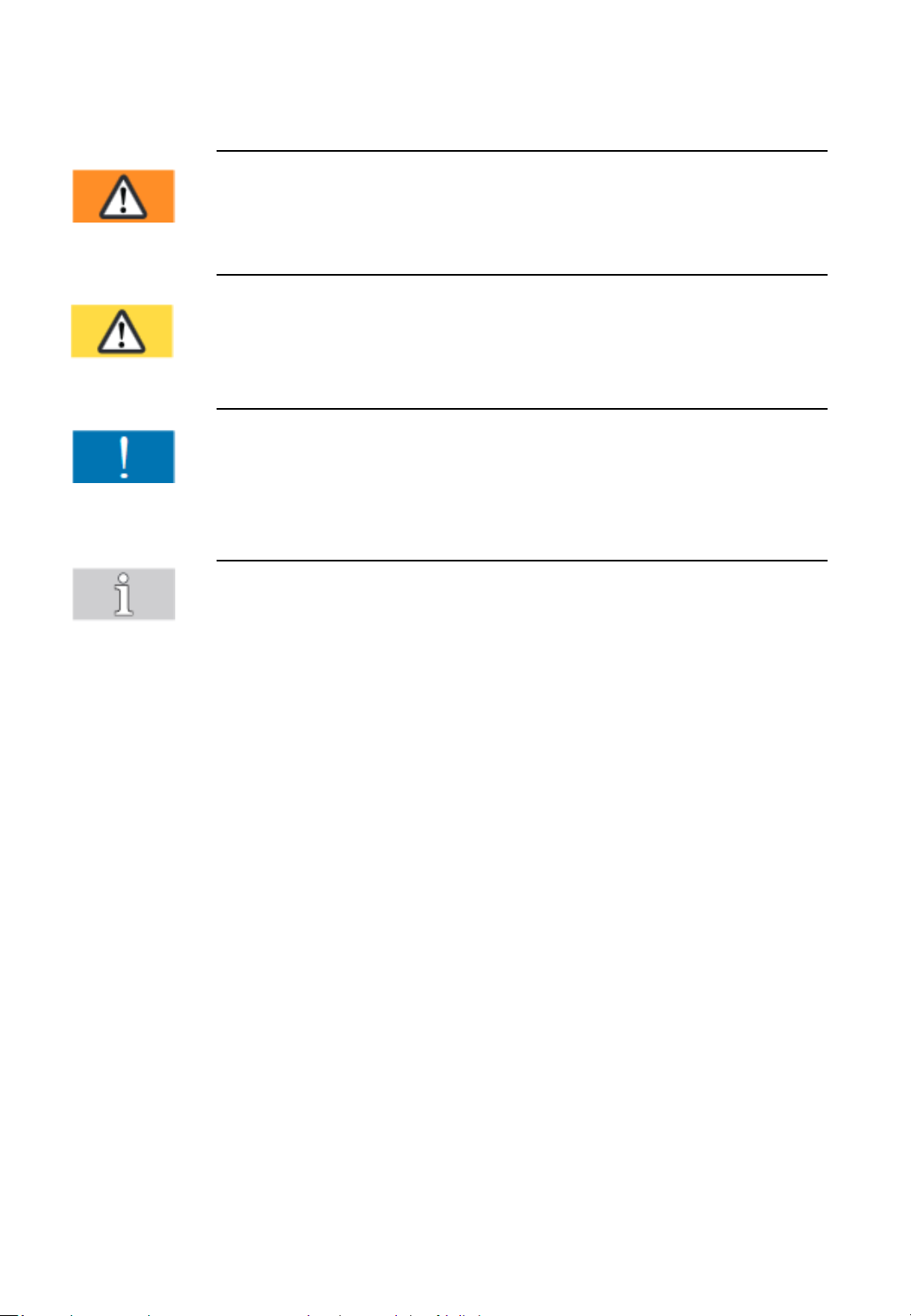
Meaning of warning symbols, usage conventions
Warning
Marks a hazard with moderate risk.
If not avoided, it can result in death or serious injury.
Caution
Marks a hazard with a minor risk.
If not avoided, it can result in a minor or moderate injury.
Attention
Marks a situation to be considered.
If not considered, it can lead to material damage or poor
operating results.
Marks useful, additional information.
2.1 Notes an environmental protection
Physical or chemical materials dangerous to health have not been used
for manufacturing the strapping system.
Concerning waste disposal, valid national rules and regulations have to
be considered. Take care about disposing packaging, the product itself
and parts accordingly.
Special dealers offer disposal according to proper environmental
protection.
- Do not open the battery
- Do not throw the used battery into the domestic waste bin, into fire or
into water.
- 11 -
Page 12
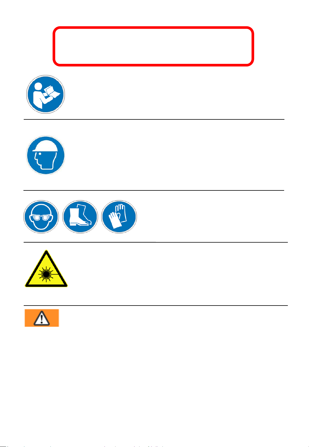
3. Safety regulations
Inform yourself!
Before usage, the manual has to be read and understood.
Service and maintenance has to be done by trained staff only.
Wear a safety helmet!
Wear a safety helmet, when strapping pallets higher than 1.20m.
The duty wearing a helmet, can be avoided, if the user was taught
about the risk of injury by the plastic chain falling.
This instruction has to be recorded in writing.
Protect yourself!
Wear eye and hand protection (cut proof
gloves) and also safety shoes.
Attention: Laser beam!
Direct eye contact with the laser beam or reflecting radiation
may result in permanent eye injuries. Never look direct in the
laser.
Laser category 2 Power: 10 mW
DIN EN 60825-1:2015-07 Wavelength: 635 nm
Warning:
Strap tensioning or strapping, danger of jamming and crushing.
Do not place hands or other body parts between the strap and
the packaged goods during the strapping process. Ensure that
there are no other persons in the hazardous zone..
For an emergency stop in the case of danger (trapped person):
• To release tension (before welding), open the rocker lever.
• After welding, cut the strap with a suitable tool (strap cutter)
- 12 -
Page 13
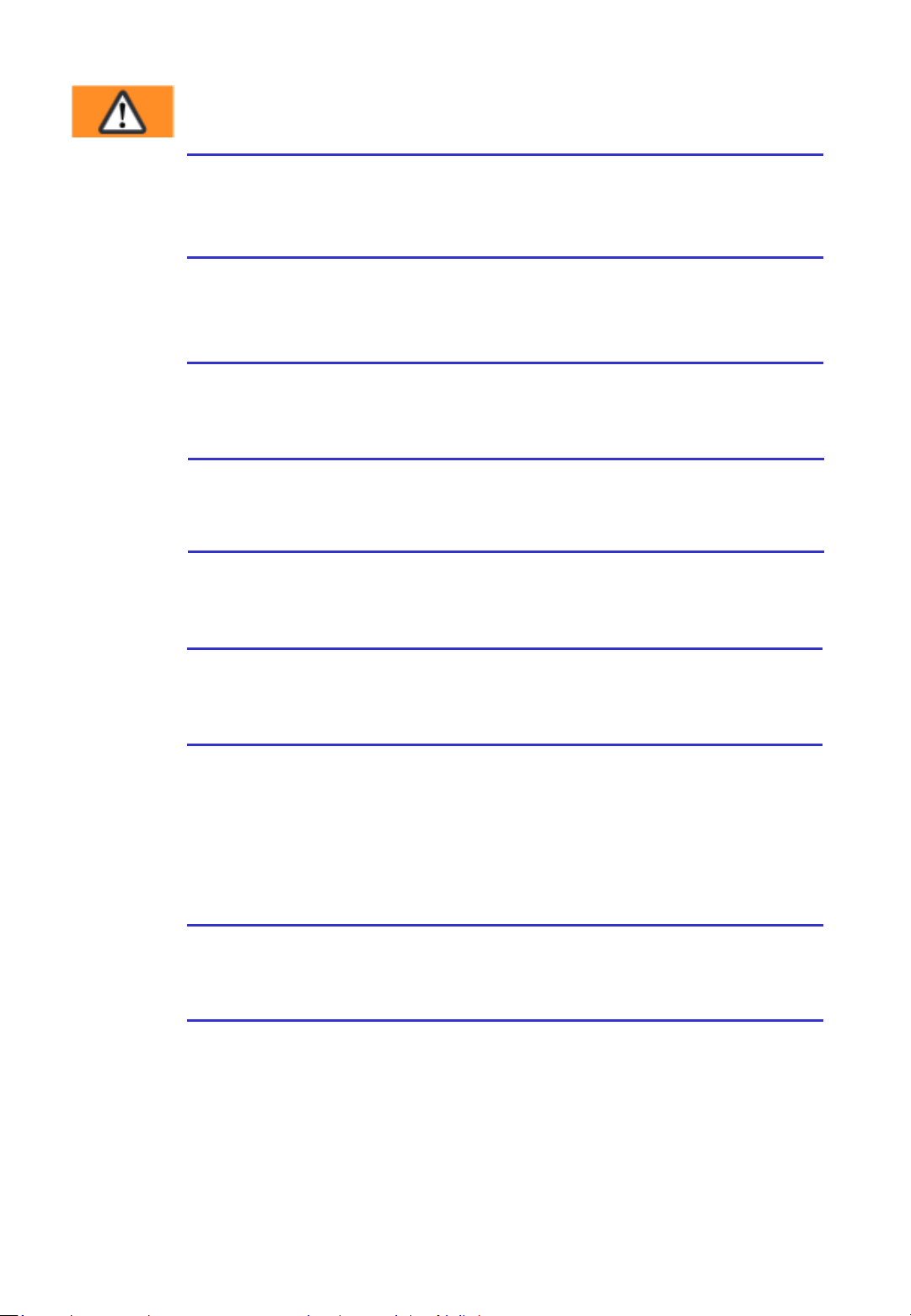
Warning:
Following hazards can result in serious injuries:
Breaking strap, risk of injury
When being tensioned, the strap may break and rip. Do not stand in
line with the strap and wear eye protection.
Strap ends snapping back, risk of injury
When cutting strap, hold the upper portion and stand aside. Do not
stand in line with the strap and wear eye protection.
ChainLance, risk of tripping
When parking the strapping system, the ChainLance must be fully
inside the strapping system. The sledge must not stick out.
Strap waste, risk of tripping
Make sure any strap waste, which possibly appeared, will be removed
from the floor quickly.
Sealing head and ChainLance, risk of crushing
Do not put your fingers into the area of the tension wheel of the
sealing head and into the ChainLance.
Reversing sledge, risk of crushing
Especially around the entire surroundings of the reversing sledge,
there is a risk of squeezing.
Hazardous area, risk of crushing and risk of injury
Make sure before each strapping cycle, there is no person in the
hazardous area (especially of the ChainLance) and nobody can enter
that area. This is due, especially for the limited or bad visible area, on
the opposite site of the pallet (users view). During strapping, there
must not be any hands or body parts between strap and goods.
Power source, risk of injury
Before maintenance or repair works: Switch main switch to “0” and
unplug the cable from the battery.
EX Areas, risk of explosion
The system must not be used in areas with explosive atmospheres.
- 13 -
Page 14
Warning:
Following hazards can cause serious injuries:
ChainLance, risk of injury
After the ChainLance moved up on the opposite side of the pallet, it
falls towards the user with its own weight.
Used without paying attention, the ChainLance can fall on the head
of the user and cause injuries. When using the system, watch out
and be concentrated and catch the ChainLance, when it falls over.
Loose and falling goods
Check the weld. Never transport or move strapped goods with an
improper welded strap.
Caution:
Following hazards can result in minor or moderate injuries:
Strap roll, risk of injury
If the strap roll is 20 kg or heavier, 2 persons need to lift it.
Tilting danger
Strapping pallets should, whenever possible, take place in areas with
an even surface. When using the strapping system on inclined
surfaces, after positioning and before strapping, the brakes of the
castor wheels on the strap side of the strapping system have to be
Attention:
Avoid damages:
Water damages
For cleaning do not use water or steam.
Visual inspection
Before using the strapping system the first time, a visual inspection
has to be done.
Only use original ErgoPack spare parts!
Warranty and liability become invalid if other parts are used.
- 14 -
Page 15

Intended use
This strapping system is designed for strapping pallets/ loading carriers. The
strapping system has been developed and constructed for safe operation
when strapping.
The system is only to be used for strapping with plastic straps
(polypropylene and polyester). Strapping with a steel strap is not possible
with this strapping system.
The system is not designed to strap aliments which are not packaged.
The set up tension force must correspond to the packaged goods to be
strapped. The construction of the strapping system does not consider any
risk to damage goods, because of the strapping itself and/ or improper set
tension force.
3.1 Safety regulations for battery pack and
charger
• Check the plug and the cable before each use and have them replaced
by a specialist if they are damaged
• Do not use any batteries from other manufacturers, use original spare
parts only.
• Keep the connection plug to the battery pack away from non-related
objects and dirt.
• Protect the charger from moisture; operate it in dry rooms only.
• Do not open the battery and protect it from shock, heat and fire.
Danger of explosion!
• Store batteries in a dry frost-proof place. The ambient temperature
must not exceed 50°C and must not fall below -5°C.
• Damaged batteries may not be reused.
- 15 -
Page 16

4. Description
4.1 Construction
Fig. 3
Control unit with drive
Cutter
Strap brake
Fig. 1
Fig. 2
Fig. 4
Sealing head
Sliding window with safety switch
Tool-Lift
Cover of battery pack
- 16 -
Page 17
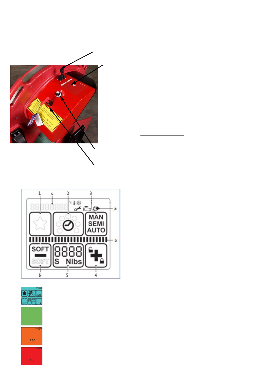
4.2 Operating panel strapping system
Joystick to move “ChainLance“ in and out
with precision speed control.
LED display
Permanent light green = battery full
Permanent light
green + yellow = battery will soon be empty
permanent yellow light = battery empty, control unit
switches off
(Control unit switches off when battery voltage ≤ 23,7V)
Flashing green + yellow = teaching mode
Flashing light green or yellow = setup mode
Quickly flashing red = sliding window open
Fig. 5
Rotary switch: A = strapping mode
B = setup mode
Main switch “power supply 1/0“
4.3 Operating panel sealing head
1 "Favorite"
2 "Welding time"
3 "Operating mode"
4 "Plus & Keylock"
5 "Tensioning force"
6 "Minus & Soft tension"
a Display "Information symbols„
b Status indicator bar “Tensioning/Welding“
c Display "Messages"
Fig. 6
Display activated.
Welding process is finished, tool can be removed
Application error: temporary system error, can be rectified by the operator
Tool fault: static system error, rectify error.If the error cannot be rectified
-> Service department ErgoPack
- 17-
Page 18
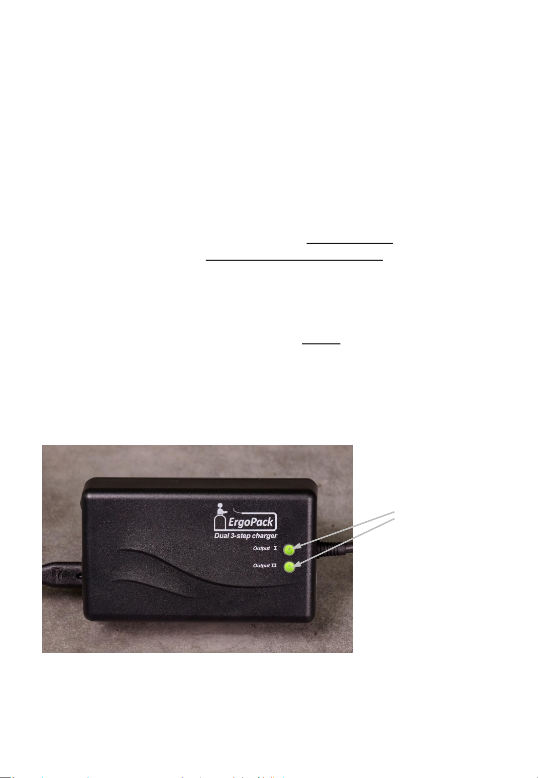
4.4 Indications of the Dual-Charger
Inside the red battery housing there are two 12V batteries installed.
The dual charger charges each of the two batteries separately.
The dual charger has one LED- indication for each of the two 12V
batteries. (Output I and Output II), indicating the charging status of
each battery.
LED permanent yellow = Charging battery. Do not remove
battery pack from the charger!
LED permanent green = Battery fully charged, charger witches
into preserving mode.
Note: The battery pack only is fully charged, if both LED indication
lights are permanent green!
Fig. 7
LED indication
- 18-
Page 19

5. Commissioning
Attention!
Before using the strapping system for the first time, a visual inspection for
exterior damages has to be done.
5.1 Battery charger
The main voltage must comply with the details on the type plate.
The charger is only suitable for charging the delivered 24V lead battery.
5.2 Charging the battery pack
1.) Connect charger to the main voltage.
2.) Open cover of battery case (by pulling at
the outer corners as shown below.)
Fig. 8
- 19 -
Page 20
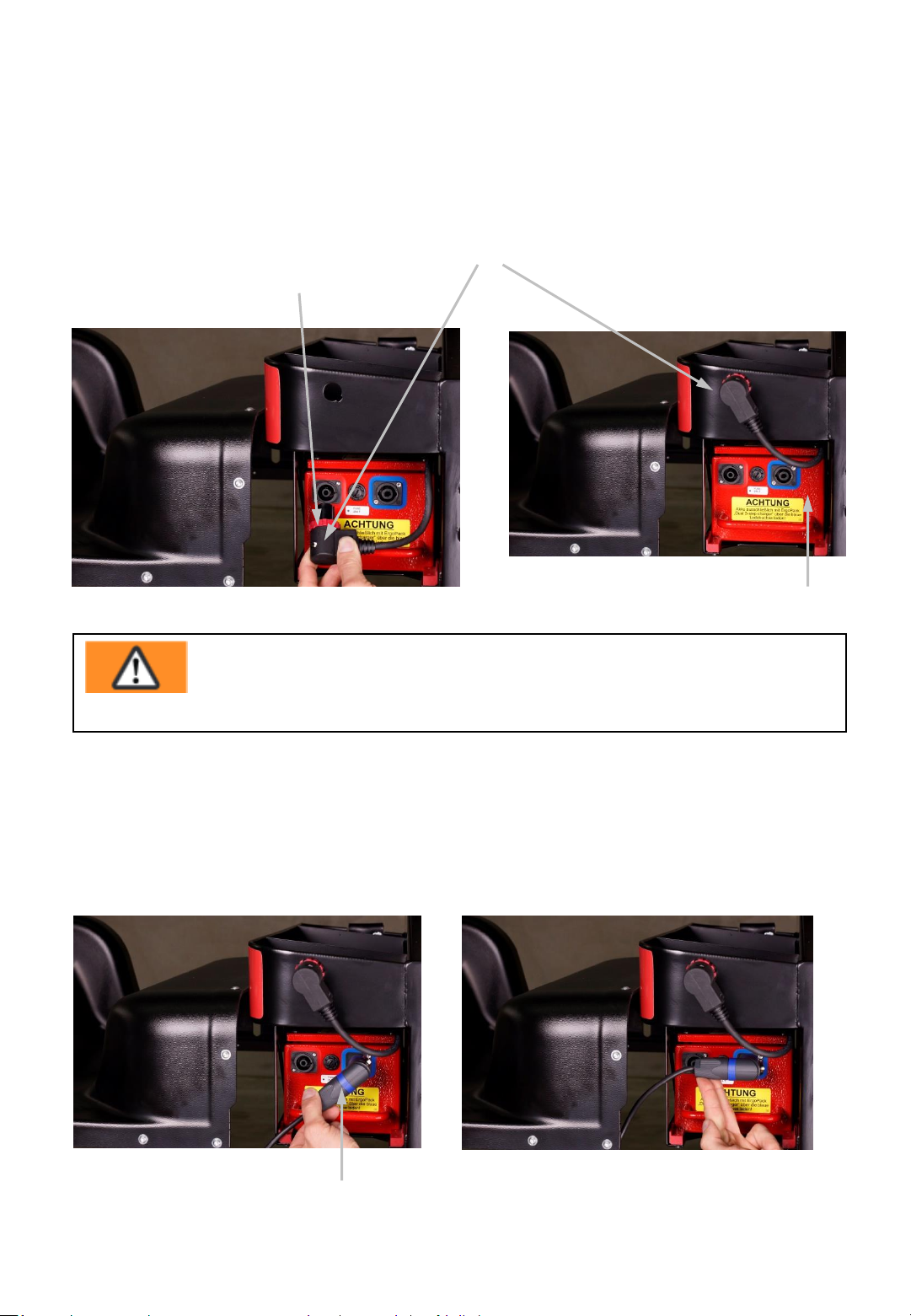
3.) Turn the red ring (12) of the plug (13)
on the battery pack (7) counter clockwise.
4.) Disconnect the plug (13) from the battery pack and
put it into the hole of the storage box above.
13
12
Fig. 10a
Fig. 9
7
Warning!
Charge the battery pack only with the ErgoPack Dual-3-step
charger through the blue socket!
5.) Put the plug (14) of the charger into the blue charging socket of the battery
pack (7) as shown in Fig 10b by slanting to the lower left corner. Thereafter turn
the plug clockwise by 45°as shown in Fig. 10c until final snap in
Fig. 10b
Fig. 10c
14
- 20-
Page 21
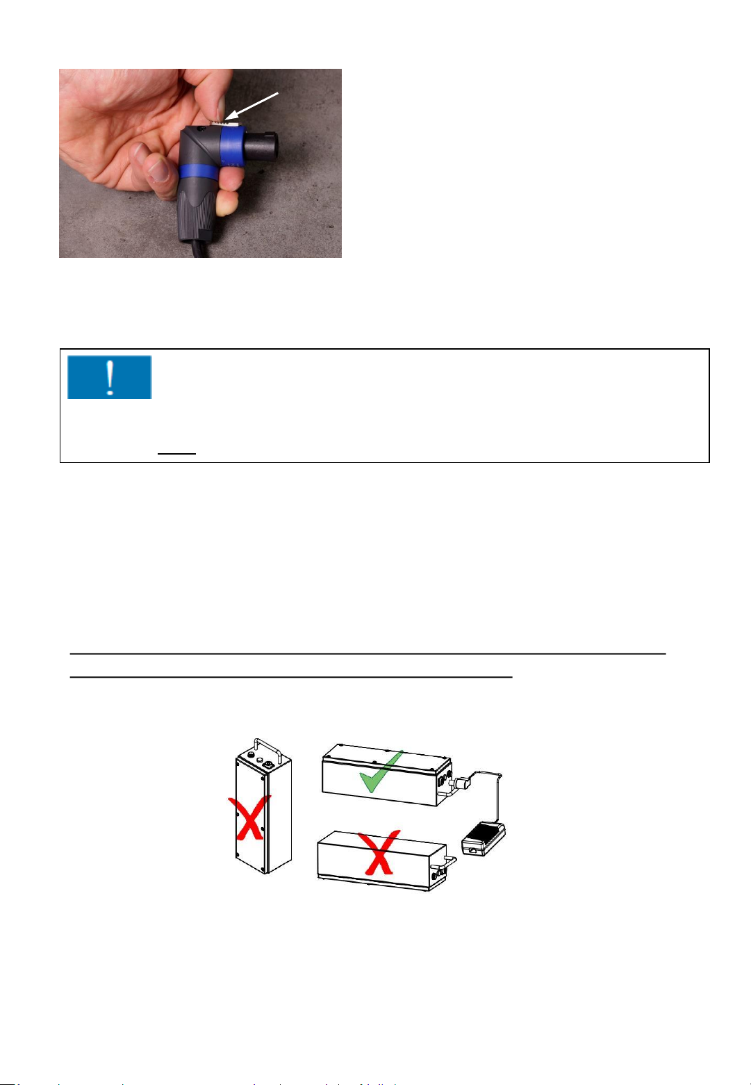
15
6.) To remove the blue charging plug after
charging is completed please proceed
as follows:
a) pull the silver locking bar (15)
backwards
b) turn the plug by 45° counter clockwise
c) remove the plug
Fig. 10d
Attention!
The charging time is approximately 8 hours. The battery pack is fully charged
not before both LED indication lights on the charger are shining green!
The maximum charging current flows if the temperature of the battery pack
is between 5 - 40°C. Avoid battery temperatures below 0°C when charging.
You achieve the longest life span, if the battery pack is charged daily
and is not being operated until the control unit switches off.
(only the yellow LED light is shining on the control box).
During charging, the battery pack always has to be in a horizontal position
(cover upside, battery must not be in upright position).
Fig. 11
- 21 -
Page 22
6. Operation
6.1 Setting strap width at the sealing head
The sealing head can be used with different strap widths:
ErgoPack 713E: 9-10mm or 11-13mm
ErgoPack 726E: 12-13mm or 15-16mm
ErgoPack 745E: 15-16mm or 18-19mm
The setting of the strap width is explained using the example of model 726E.
The setting of the strap width with the models 713E from 9-10 mm to 11-13 mm
and 745E from 15-16 mm to 18-19 mm works accordingly.
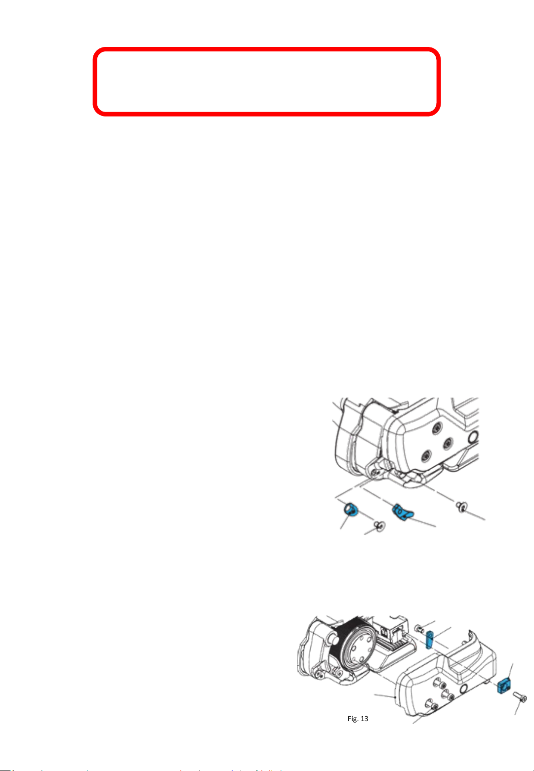
a) Change strap width from 12–13 mm to 15–16 mm
• Switch the strapping system off
• Release three cylinder screws Torx (6). Lift the rocker lever
towards the handle, release cylinder screw Torx (7) and
remove strap guide rear13mm (8).
• Remove side cover (5).
• Release counter-sunk screw Torx (2) and remove strap guide
front 13 mm (1).
• Release counter-sunk screw Torx (4) and remove strap guide
front 13 mm (3).
• Release cylinder screw Torx (10) and remove strap guide
rear 13 mm (9).
• Fit side cover (5) (secure cylinder screw with screw locking
varnish “medium-tight”. Install strap guide rear 16 mm (8).
b) Change strap width from 15-16mm to 12-13 mm
•Release three cylinder screws Torx (6). Lift the rocker
lever towards the handle, release cylinder screw Torx (7)
and remove trap guide rear 16 mm (8).
•Remove side cover (5).
•Fit strap guide front 13 mm (1) (secure counter-sunk
screw with screw locking varnish “medium-tight”).
•Fit strap guide front 13 mm (3) (secure counter-sunk screw
with screw locking varnish “medium-tight”).
•Fit strap guide rear 13 mm (9) (secure cylinder screw
with screw locking varnish “medium-tight”).
•Fit side cover (5) (secure cylinder screw with screw locking
varnish “medium-tight”). Install strap guide rear 13 mm (8).
- 22-
1
2
5
Fig. 13
3
Fig. 12
10
9
6
4
8
7
Page 23
6.2 Switching on the control unit
1. Step
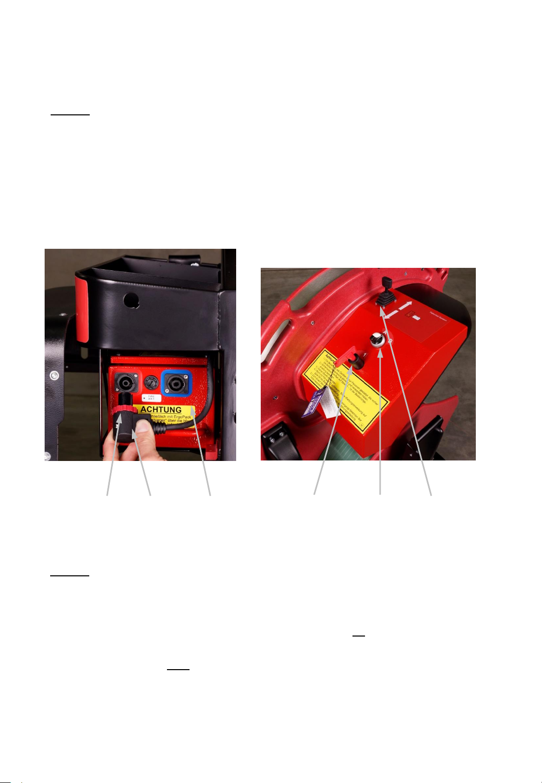
Charge the battery pack as described under 5.2.
Plug in the connector of the power cable (13) into the socket of the
battery pack (7) and lock it by turning the red ring (12) clockwise.
Lock the cover of the battery case again.
Turn the main switch (11) to the right to operating mode “1“
Set the operating mode switch (10) to operating mode “A“.
Fig. 14 Fig. 15
13 12
2. Step
2 LEDs (green and yellow) are now flashing. The control unit is in
teaching mode.
Now move the joystick (8) completely to “move out“ or “move in
direction“ and keep it pushed until the green LED permanently is
shining (if the green and the yellow LED are shining, the battery is
not fully charged but you nevertheless can continue).
The control unit/ sealing head is ready for operation.
7
- 23 -
11
10
8
Page 24
6.3 Setting the strap tensioning range at the
sealing head
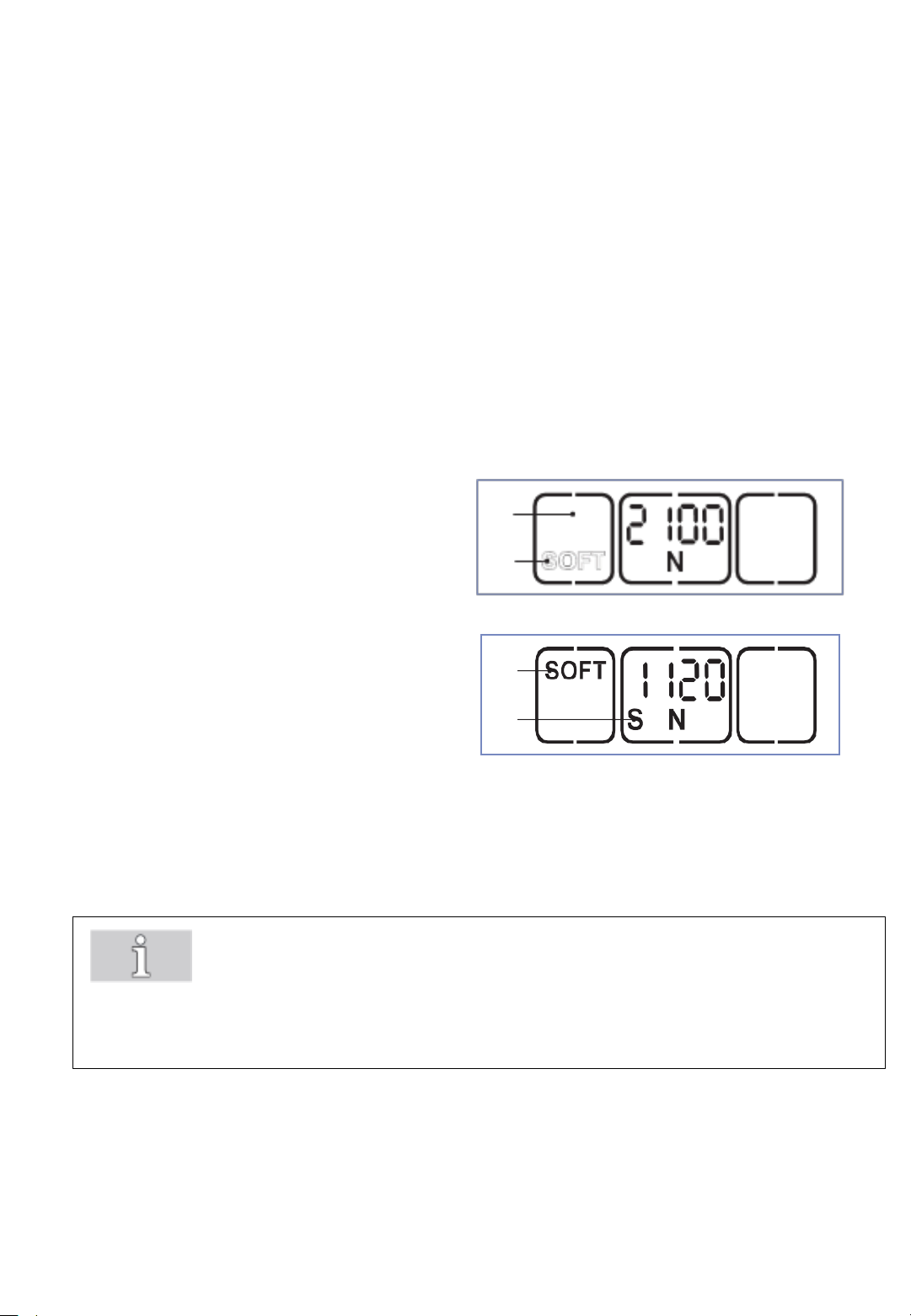
Two strap tensioning ranges can be set at the sealing head:
NORMAL = 400-1200N (713E); 900-2500N (726E); 1300-4500N (745E),
standard tension range for PET strap
SOFT = 150-750N (713E); 400-1360N (726E) bzw. 400-1600N (745E),
soft tension for PP straps
Press "Soft" button (1).
2
Fig. 16
1
3
4
The soft mode is deactivated when the
"SOFT" display (2) changes position and
is shown outlined.
Press "Soft" button (1).
The soft mode is activated when the
"SOFT" display (3) changes position and
is shown in bold.
The displayed tension force is reduced
correspondingly.
On the left under the tension force an "S"
(4) also appears.
Important!
Always use the SOFT tension mode when working with PP-strap!
By using the Soft mode, the tension wheel accelerates more slowly
and avoids excessive strap waste when sealing with PP strap.
- 24 -
Page 25
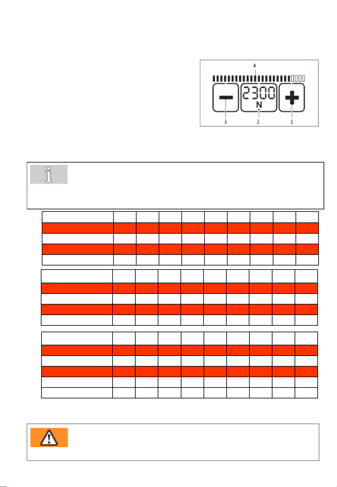
6.4 Setting strap tension at the sealing head
The set tension force is displayed continuously when
the tool is ready for operation.
Press "Tension force" button (2).
• The set tension force flashes for 5 seconds.
• The + (1) and – (3) buttons appear.
• Unused displays disappear.
Press the + (1) or – (3) button until the desired
tension force is displayed.
• The status indicator bar (4) shows the set tension
force in relation to the possible maximum value.
Save: Press the "Tension force" button (2) or wait
for 5 seconds.
• Switch between display in "N" or "lbf": Press the flashing "Tension force" button (2) for two
seconds.
• Every time the button is pressed an acoustic signal confirms the action.
• The tension force is displayed continuously when the tool is operational.
• Setting soft tension (Section 6.3).
Fig. 17a
713E
Standard N* 400 500 600 700 800 900 1000 1100 1200
Soft N 150 225 300 375 450 525 600 675 750
726E
Standard N* 900 1100 1300 1500 1700 1900 2100 2300 2500
Soft N 400 520 640 760 880 1000 1120 1240 1360
745E
Standard N* 1300 1700 2100 2500 2900 3300 3700 4100 4500
Soft N 400 550 700 850 1000 1150 1300 1450 1600
lbf* 90 110 135 155 180 200 225 250 270
lbf 33 50 67 85 100 120 135 150 165
lbf* 200 250 290 340 380 430 470 520 560
lbf 90 115 145 170 200 225 250 280 305
lbf* 290 380 470 560 650 740 830 920 1000
lbf 90 120 160 190 225 260 290 325 360
(rounded values)
* N = Newton, lbf = pound-force per square inch
Warning!
Adjusted tension force must relate to the goods to be strapped.Possible hazards caused by
damages of dangerous goods or their packaging are not considered with the design of the
strapping system.
- 25 -
Page 26
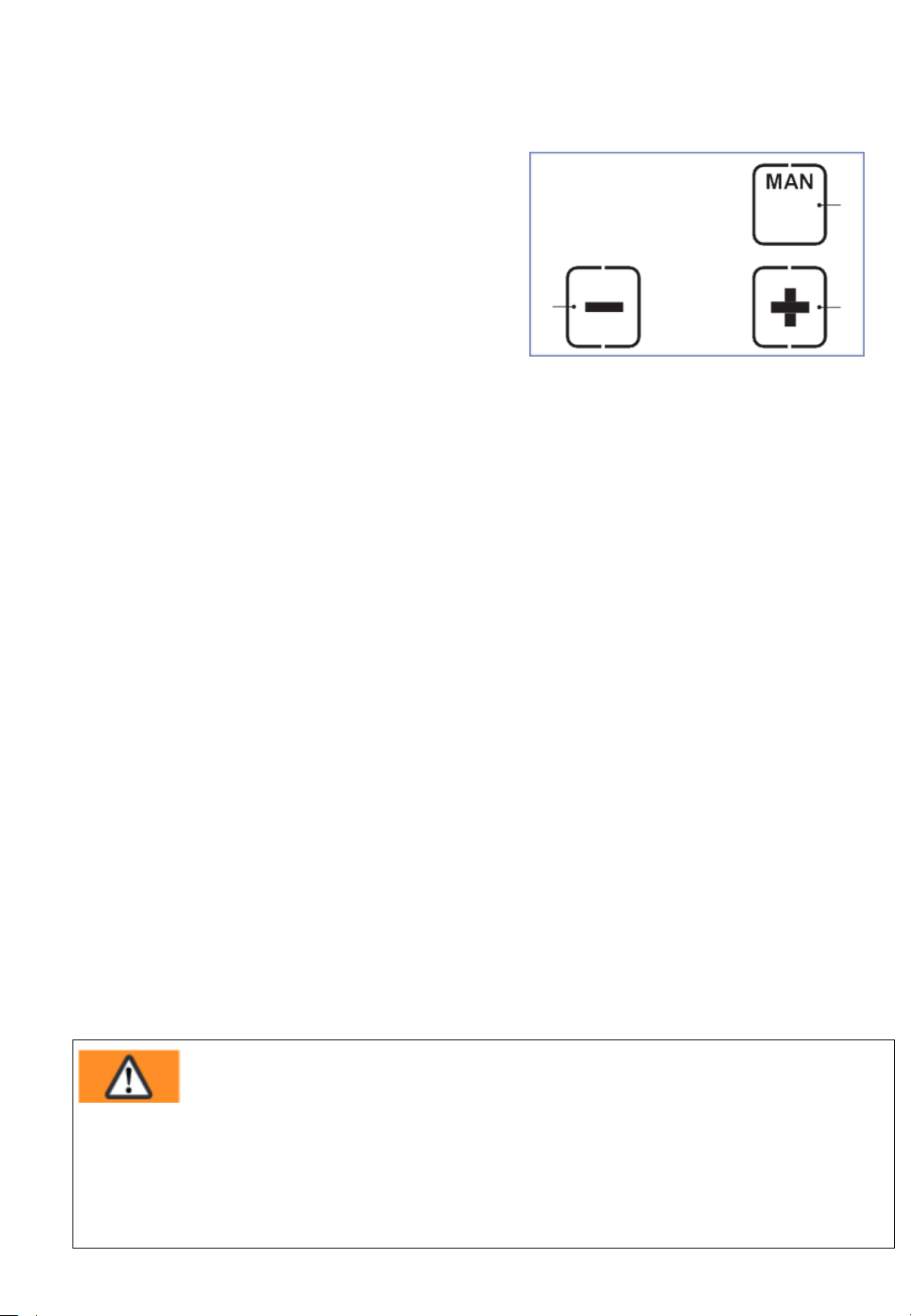
6.5 Setting mode of operation at the sealing head
Press the "Operating mode" button (1).
• Unused displays disappear.
• The currently set operating mode flashes
for 5 seconds.
• + and – appear.
Press the + (2) or – (3) button until the
3
desired operating mode is displayed.
Fig. 17b
MAN / SEMI / AUTO
By pressing the "Operating mode" button (1) again, or after waiting for a
period of 5 seconds, the set mode is saved.
Every operating mode can also be selected for the "Soft tension" tension
range (Side 24).
• MAN-Manual
The tensioning button must be pulled and held until the desired strap
tension has been reached. The welding button must then be briefly
pressed so that the straps are welded and the upper strap is cut off.
1
2
• SEMI–Semi-automatic strapping (standard/factory setting)
The tensioning button must be pulled and held until the set tension force
has been reached. The straps are then automatically welded and the
upper strap is cut off. It can be welded manually at any time by pressing
the welding button.
• AUTO–Fully automatic strapping*
The tensioning button has to be pulled (touched) once only. This triggers the
tensioning process. Once the set tension force has been reached, the straps
are automatically welded and the upper strap is cut off.
* This operating mode AUTO = Fully automatic strapping is factory
blocked! Activation only through your ErgoPack service partner possible.
WARNING
Strap tensioning or strapping, danger of jamming and crushing
Do not place hands or other body parts between the strap and the packaged goods
during the strapping process. Ensure that there are no other persons in the hazard zone
For an emergency stop in the case of danger (trapped person):
To release the strap tension (before welding), actuate the rocker lever. In operating mode
AUTO, also the tensioning or welding button can be pressed again. After welding, cut the
strap using a tool (strap cutter).
- 26 -
Page 27
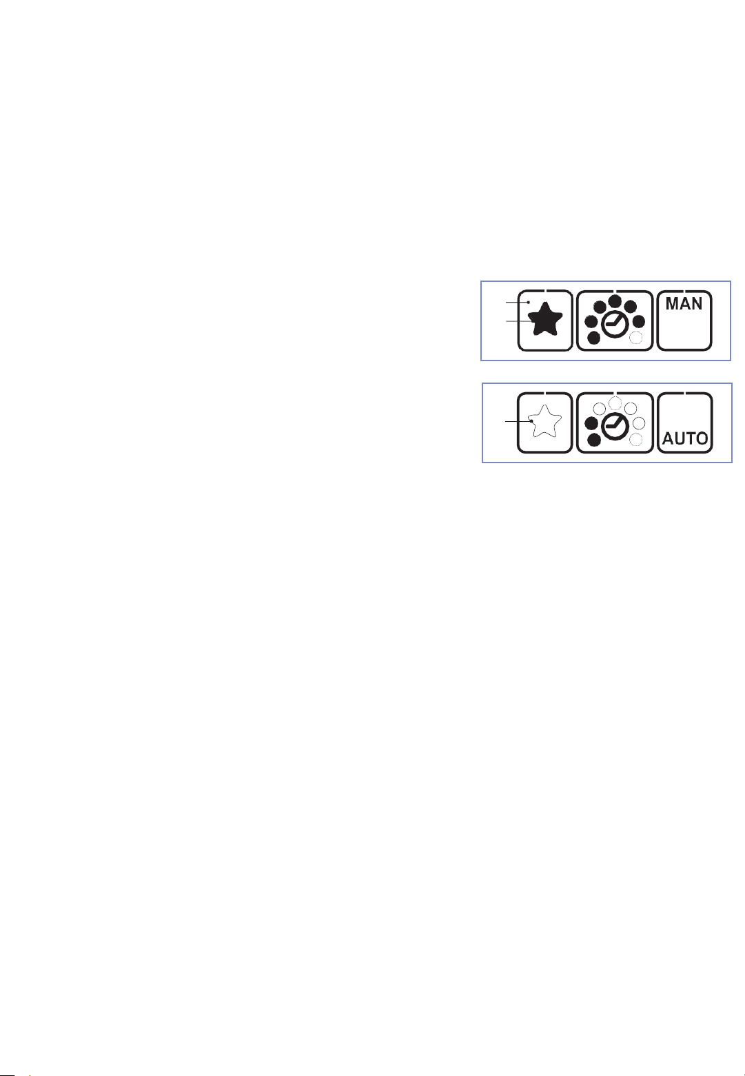
6.6 Select favourite*
The function „favourite“ activates a second settings level, whose parameters can
be set freely like those of the main level.
This enables the operator to quickly change from one setting into the other.
Deactivate favourite:
• Press „favourite“ button (1).
The star (2) changes from bold
to outlined. All parameters change
to the pre-set values of this
settings level.
Activate favourite:
• Press „favourite“button (1). The star (3)
changes from outlined to bold. All
parameters change to the pre-set values of
this settings level.
1
2
Fig. 17c
3
Fig. 17d
• The operating mode favourite is factory blocked! Activation only through your
ErgoPack service partner possible.
- 27 -
Page 28
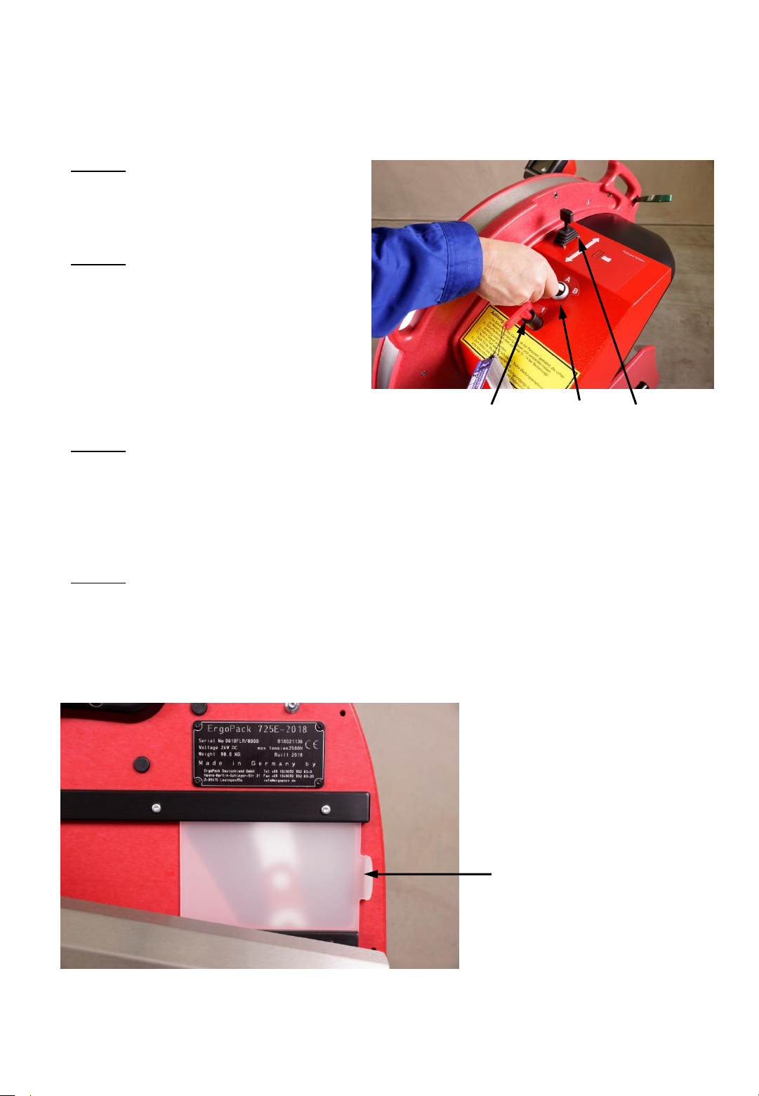
6.7 Changing strap coil
1. Step
Switch on the control unit key as
described under point 6.2
2. Step
Set the operating mode switch (3)
to position “B“
(green LED flashes / green and
yellow LED are flashing if the
battery is not fully charged)
3. Step
You can use the joystick (8) to position the ChainLance so that the red chain
link is in the middle of the sliding window (6).
The sliding windows must be closed during this operation!
4. Step
Open the sliding window (6). (red LED flashes quickly).
The control unit automatically switches off for safety reasons when the
sliding window is open. Additionally, the main switch (11) has to be turned
to the left into pos. „0“.
Fig. 18
11
3
8
Fig. 19
6
- 28 -
Page 29
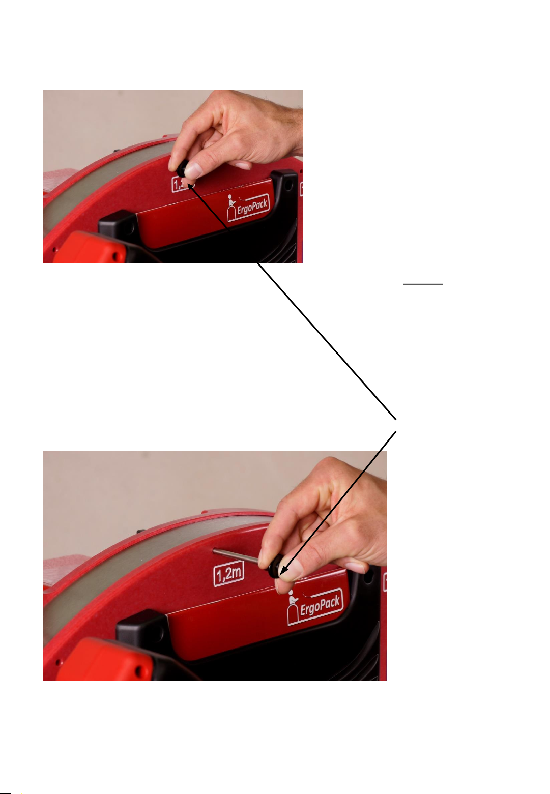
Fig. 20
5. Step
Remove the pin for
setting the pallet
width from its
position at 1,2 m.
To remove and to
insert the pin, the
button at the
center of the pin
must be pressed.
Fig. 21
- 29 -
Page 30
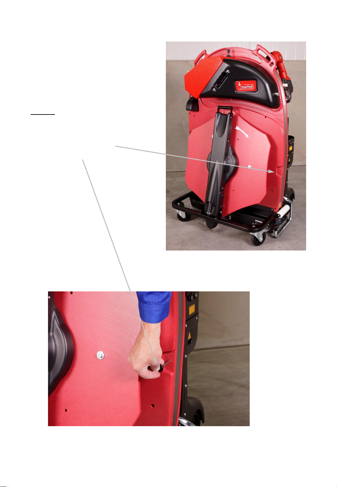
6. Step
Put the pin into the hole
with the milling groove at
the lower left side.
Fig. 22
Fig. 23
- 30 -
Page 31
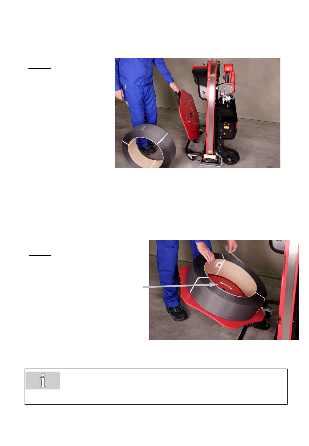
7. Step
Fold down the pivot arm
with the red circular disk
until its final stop.
Fig. 24
8. Step
Place a new strap coil onto the
red circular disk, that the strap
uncoils in the counter-clockwise
direction when looking down on
the roll.
Fig. 25
Important!
Do not yet remove the tape or adhesive tape, which fix the strap
on the coil!
- 31 -
Page 32
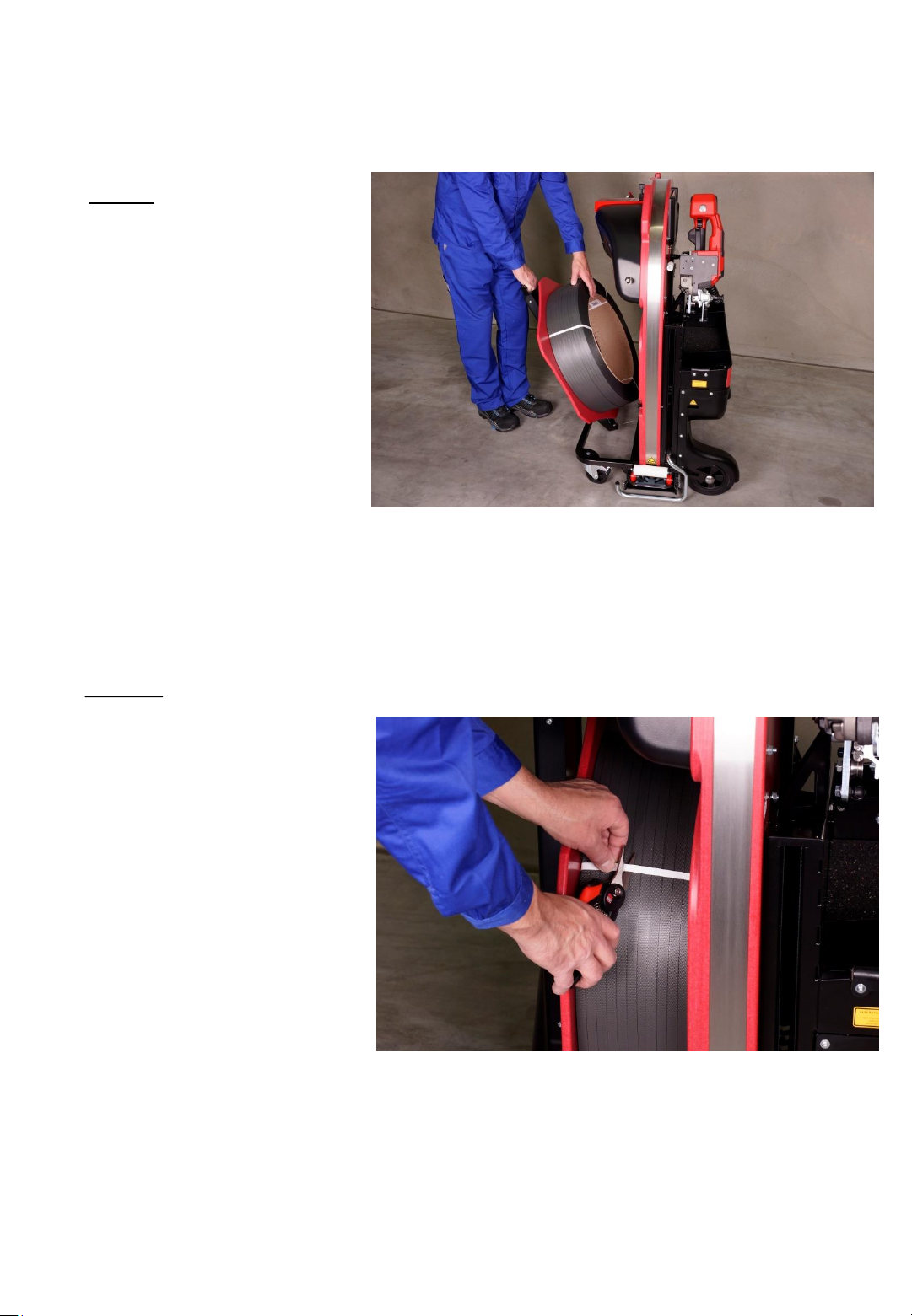
9. Step
Fold up the arm with the
strap coil again in its vertical
position as shown on the
picture.
Fig. 26
10. Step
Now, remove the tapes or
adhesive tapes fixing the
strap on the coil.
Fig. 27
- 32 -
Page 33
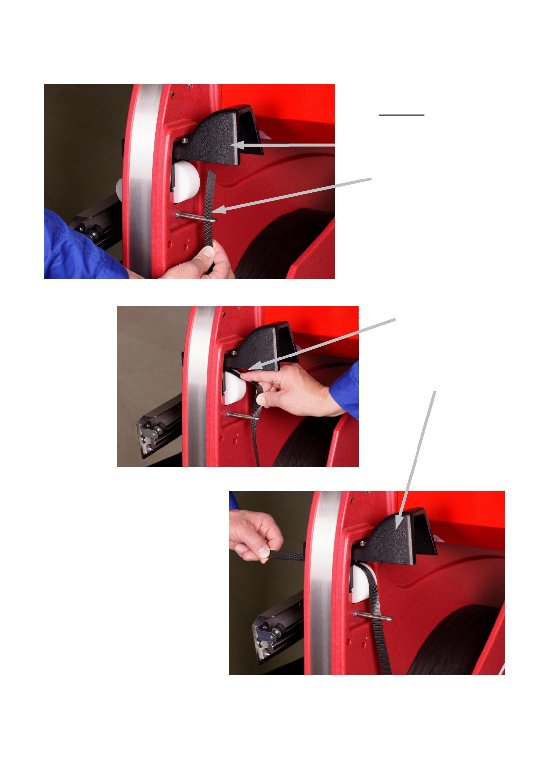
Fig. 28
11. Step
Fold up the cover of
the white roll for
strap infeed, thread
the strap through
the U-bolt…
...and over the
white roll to the
inside. Thereafter
fold the cover back
down again.
Fig. 29
Fig. 30
- 33 -
Page 34
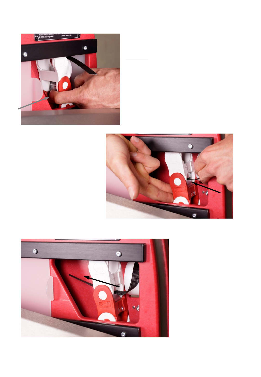
Fig. 31
….then slide the strap
from the right to the left
through the slot in the
clamp lock.
12. Step
Press from the left hand
side on the metal clamp
lock located in the red
chain link…
Fig. 33
Fig. 32
- 34-
Page 35
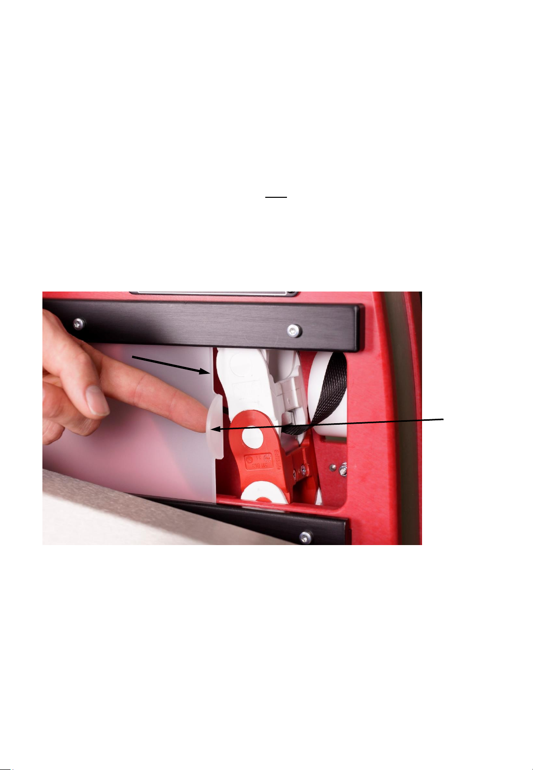
Now close the sliding window (6). Make sure that the
window is closed up to the stop. The safety switch for
the control unit will only unlock again when the
window is completely closed. (red flashing LED turns
off, green LED lights up or green and yellow LED are
lighting up)
Fig. 34
6
- 35 -
Page 36
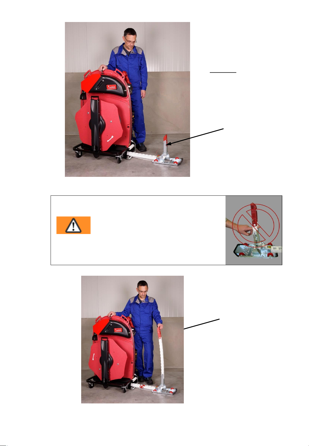
Fig. 35
Warning,
risk of injury!
Never put your fingers between the chain links.
13. Step
Press the joystick in
the “move out “
direction until the
reversing sledge tilts
upwards.
Fig. 36
Hold the end of the
ChainLance with the
left hand while you
still continue to push
the joystick in the
“move out direction“.
- 36 -
Page 37
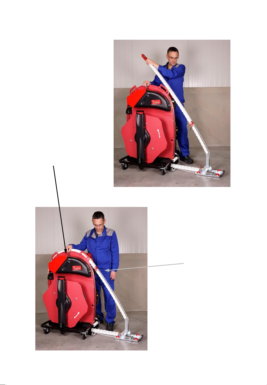
Extend the
ChainLance as far as
shown on the picture.
Then put the chain
on the strapping
system…
Fig. 37
Fig. 38
...and continue
to move out the
ChainLance until
the red chain link
is at about the
same level as the
left handle of the
system.
- 37 -
Page 38
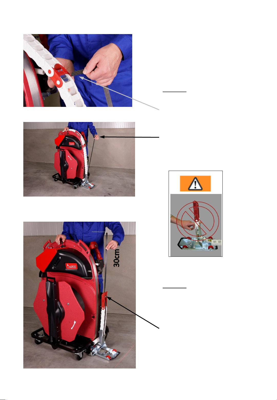
Fig. 39
Fig. 40
14. Step
Remove the strap from
the clamp lock in the
red chain link and hold
it straight up as shown.
Fig. 39
Fig. 41
15. Step
Move the ChainLance
back now by pushing
the joystick in the
„move in“ direction until
the ChainLance is
approx. 30 cm lower
than the strap you are
holding in your hand.
- 38 -
Page 39
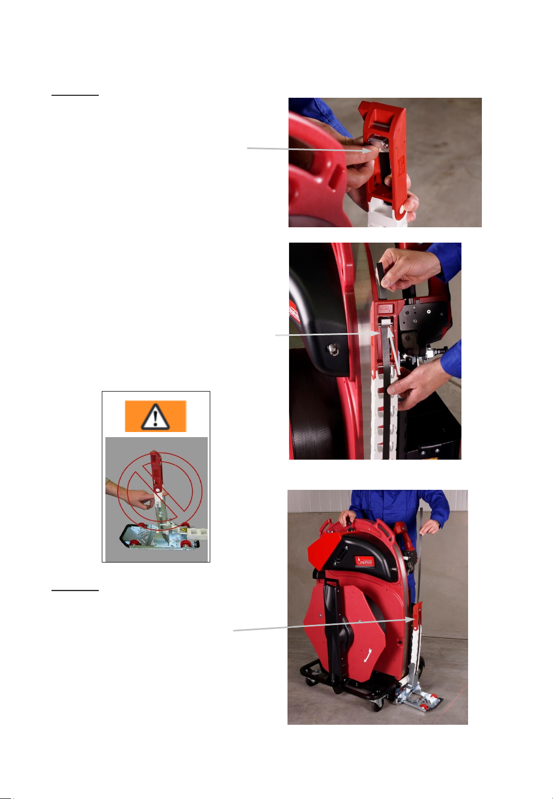
16. Step
Open the eccentric latch in the
red head piece of the
ChainLance by pushing it
inwards with your finger.
Push the strap from the back through
the head piece of the ChainLance (as
shown). The strap must pass
between the two aluminium
eccentrics.
Fig. 42
Fig. 42
17. Step
Now hold the strap
vertically so that the
strap and the
ChainLance are
straight.
Fig. 43
Fig. 44
- 39 -
Page 40
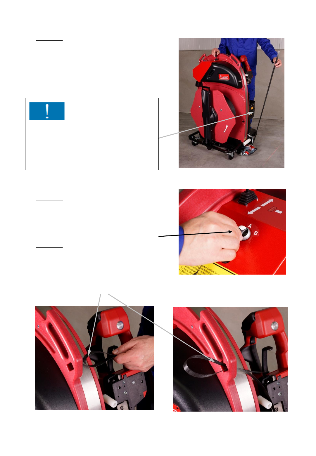
18. Step
Move the ChainLance
completely backwards by
pushing the joystick again
in the “move in“ direction.
Important !
Make sure that the strap remains
continuously tensioned while moving
back the ChainLance, to avoid the
strap being pushed into the strapping
system.
19. Step
Fig. 45
Set the operating mode switch (3) to
position “A“
3
20. Step
Place the overlapping strap
as shown with a loop
through the small slot
underneath the left handle.
Fig. 46
- 40 -
Fig. 47b Fig. 47a
Page 41
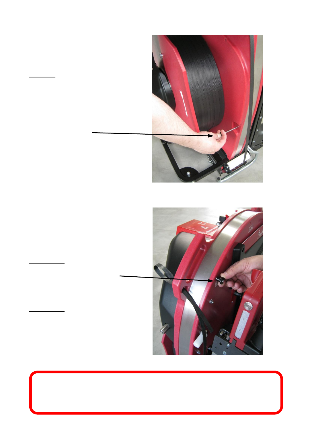
21. Step
Remove the pin for
setting the pallet
width from the hole
with the milling
grove…
...and set the requested
pallet width as shown on
the picture by placing the
pin into the next higher
size of your pallet width.
Example 1:
Pallet width 0,80 mPut the pin into the 1,0 m
position
Exampel 2:
Pallet width 1,2 m-
Put the pin into the 1,4 m
position
Fig. 48
Fig. 49
Your ErgoPack is now ready for strapping.
- 41 -
Page 42
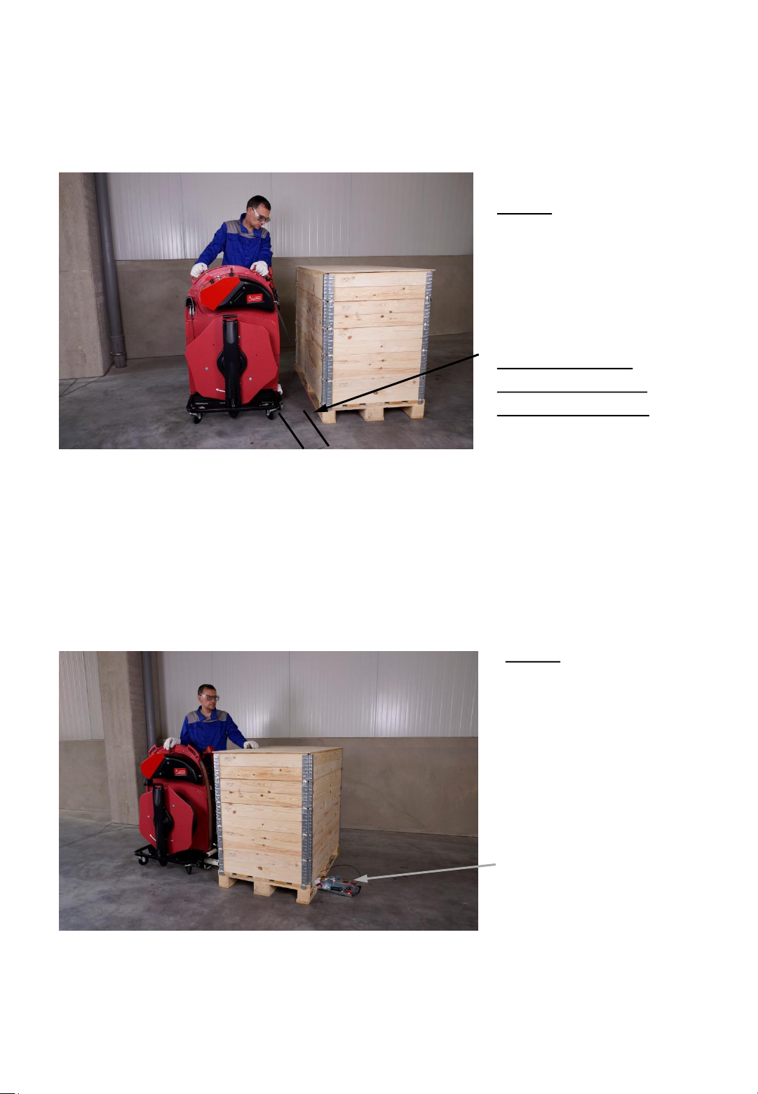
6.8 Strapping
Fig. 50
1. Step
Place the ErgoPack at
a distance of approx.
30 cm in front of the
pallet to be strapped.
If your system is
equipped with the
optional line laser:
Align the ErgoPack parallel
to the pallet so that the
laser line runs alongside
the pallet edge.
Fig. 51
2. Step
Move out the
ChainLance by
pushing the joystick
in the “move out“
direction.
The reversing sledge
leads the strap
through and
underneath the
pallet…
- 42 -
Page 43
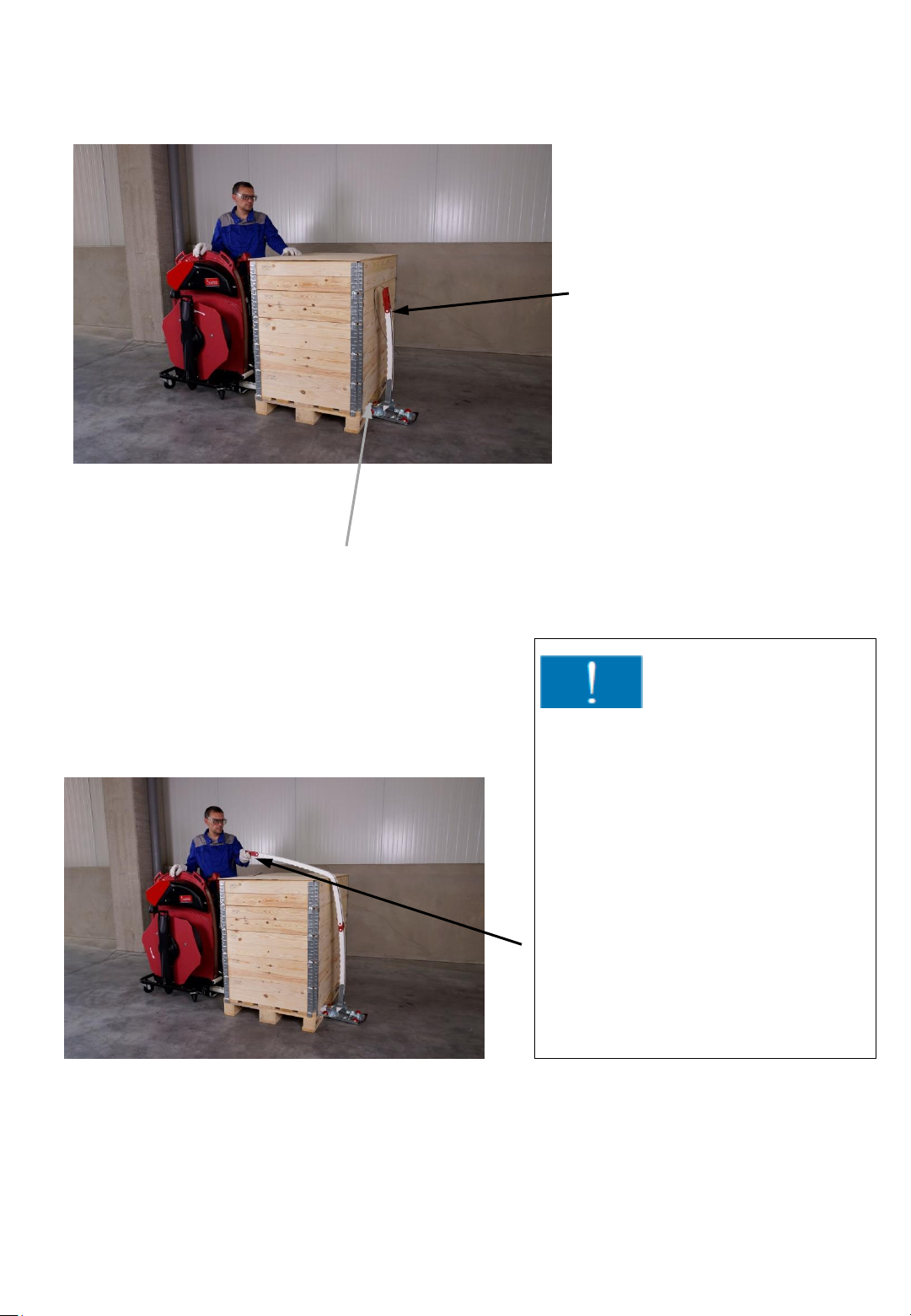
Fig. 52
If the setting of the pallet width and the
positioning of the strapping system are
correct, the distance between the chain
and the pallet is about 10 cm.
...and back up again
on the opposite
side.
Attention!
Push the joystick until the
ChainLance appears on the other
side and falls in your direction.
Fig. 53
Release the joystick, so that it
returns to the neutral position
(central position) and stops the
ChainLance moving out further.
Catch the ChainLance as shown at
the red head piece. Do not let the
ChainLance drop onto the
package!
- 43-
Page 44
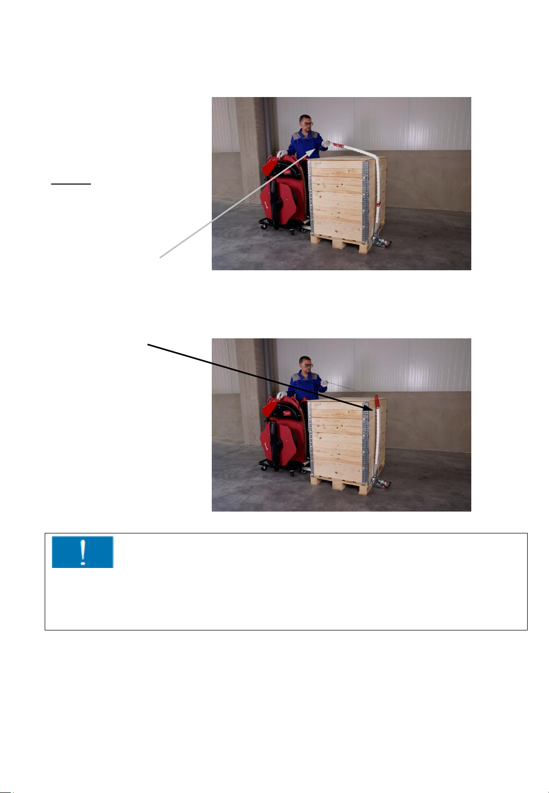
3. Step
Hold the strap with
your left hand as
shown, directly at the
head piece of the
ChainLance…
... move the
ChainLance
completely back by
pushing the joystick
in „move in“
direction.
Fig. 54
Fig. 55
Attention!
Always keep the strap slightly under tension when moving the ChainLance
backwards, to avoid that loops can be formed at the reversing sledge. Loops
may lead to malfunctions while moving back the ChainLance.
- 44 -
Page 45
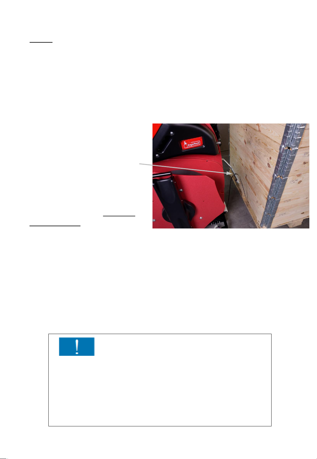
4. Step
The strap lifter comes up
automatically when the
reversing sledge moves back
into the strapping system.
Now you have to loose the
strap tension of your left hand;
otherwise the strap lifter will
not be able to come up.
The strap lifter lifts the second
end of the strap up to working
height so you can grasp it
without bending down.
Only keep the joystick pushed
until the strap lifter is fully in its
upper position.
The strap lifter automatically
moves down again after 2
seconds. (The strap lifter will
not go down automatically after
2 seconds if the upper position
has not been reached
successfully)
Fig. 56
Attention!
You have to hold the strap loosely in your hand when the
strap lifter comes up.
The strapping system automatically switches off to prevent
damages if you do not release the strap once the strap lifter
comes up. The strap lifter can be raised up again by
repeatedly pushing the joystick in the “move in direction”.
- 45 -
Page 46
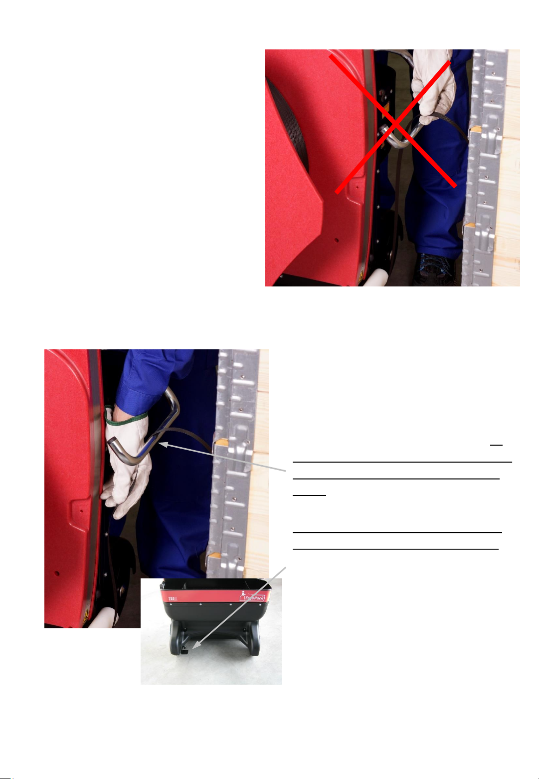
If for sealing the strap you have to
pull some additional strap out of the
strapping system, do not take the
strap directly at the strap lifter…
Fig. 57
...but about 10cm below the strap lifter.
Hold the strap with the whole hand and
pull it out of the strapping system. At
the same time, you have to let the end
of the strap slide through your other
hand!
Fig. 58a
If your strapping system is equipped
with the optional strap break relief:
Before pulling at the strap, press down
the foot pedal at the left side. This
reduces the brake force of the strap coil
and eases pulling out strap a lot.
Fig. 58b
- 46 -
Page 47
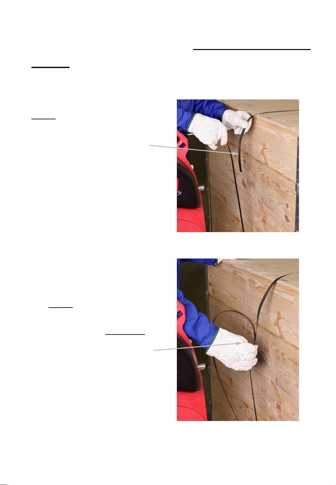
6.9 Tensioning and sealing pallets above 70cm
height
1. Step
Overlap the straps so that the end
of the strap lies underneath.
2. Step
Hold then both straps as
shown with the right hand.
The end of the strap should
lie in your hand and not
project beyond it! hold
Fig. 59
- 47-
Fig. 60
Page 48
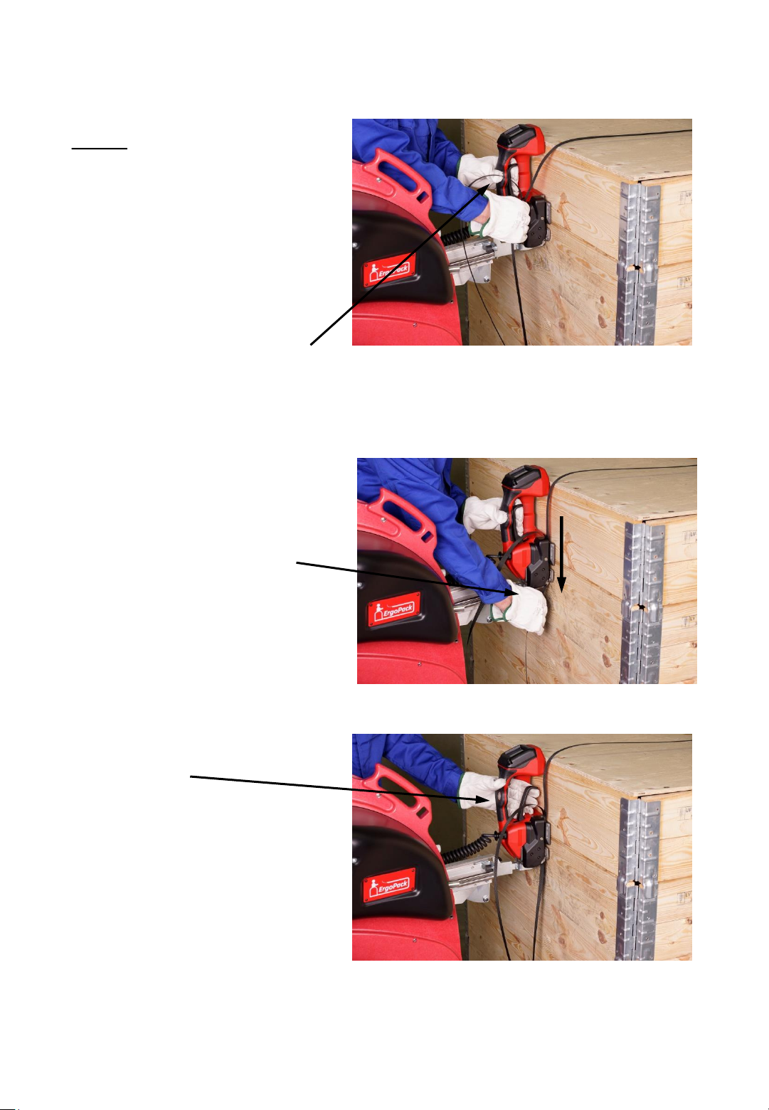
3. Step
Push the sealing head
towards the pallet with
the left hand and tilt it
forward at the same time
so that the sealing head is
parallel to the package.
Pull the rocker lever to
open the clamp of the
sealing head.
With your right hand you
can now feed the strap
from the top to the
bottom through the slot
in the sealing head.
(similar to a credit card)
Now let go of the rocker
lever
Fig. 61
Fig. 62
Fig. 62
Fig. 63
- 48 -
Page 49
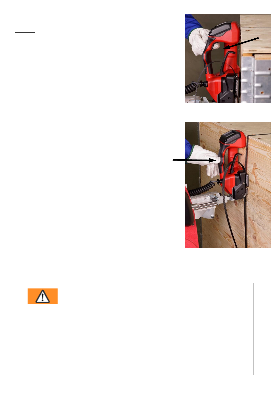
4. Step
The tensioning and sealing of the strap is different
according to the set mode (manual, semi-automatic or
automatic mode)
See to this „Setting mode of operation“ page 26
4.1 Manual tensioning and sealing
Pull the tensioning button until the required tension
force is reached (see page 26, chapter 6.5).
Thereafter, press the round welding button to weld
both straps and to cut off the upper one.
4.2 SEMI-Semi-automatic tensioning and sealing
Pull the tensioning button until the pre-set tension
force is reached. Afterwards, both straps will be
automatically welded and the upper strap will be cut
off. You can also weld the straps manually at any time
by pressing the welding button even if the pre-set
tension force was not reached.
4.3 Automatically tensioning and welding*
By a brief pulling (touching) of the tensioning button
once, the sealing process (tensioning and welding) will
be activated. Once the set tension force has been
reached, the straps are automatically welded and the
upper strap is cut off.
Fig. 64
Fig. 65
* This operating mode AUTO = Fully automatic strapping is factory blocked! Activation only through your
ErgoPack service partner possible.
Warning!
Strap tensioning or strapping, danger of jamming and crushing
Do not place hands or other body parts between the strap and the packaged
goods during the strapping process. Ensure that there are no other persons in
the hazard zone.
For an emergency stop in the case of danger (trapped person):
To release the strap tension (before welding), actuate the rocker lever, the
tensioning or welding button. After welding, cut the strap using a tool (strap
cutter).
- 49 -
Page 50
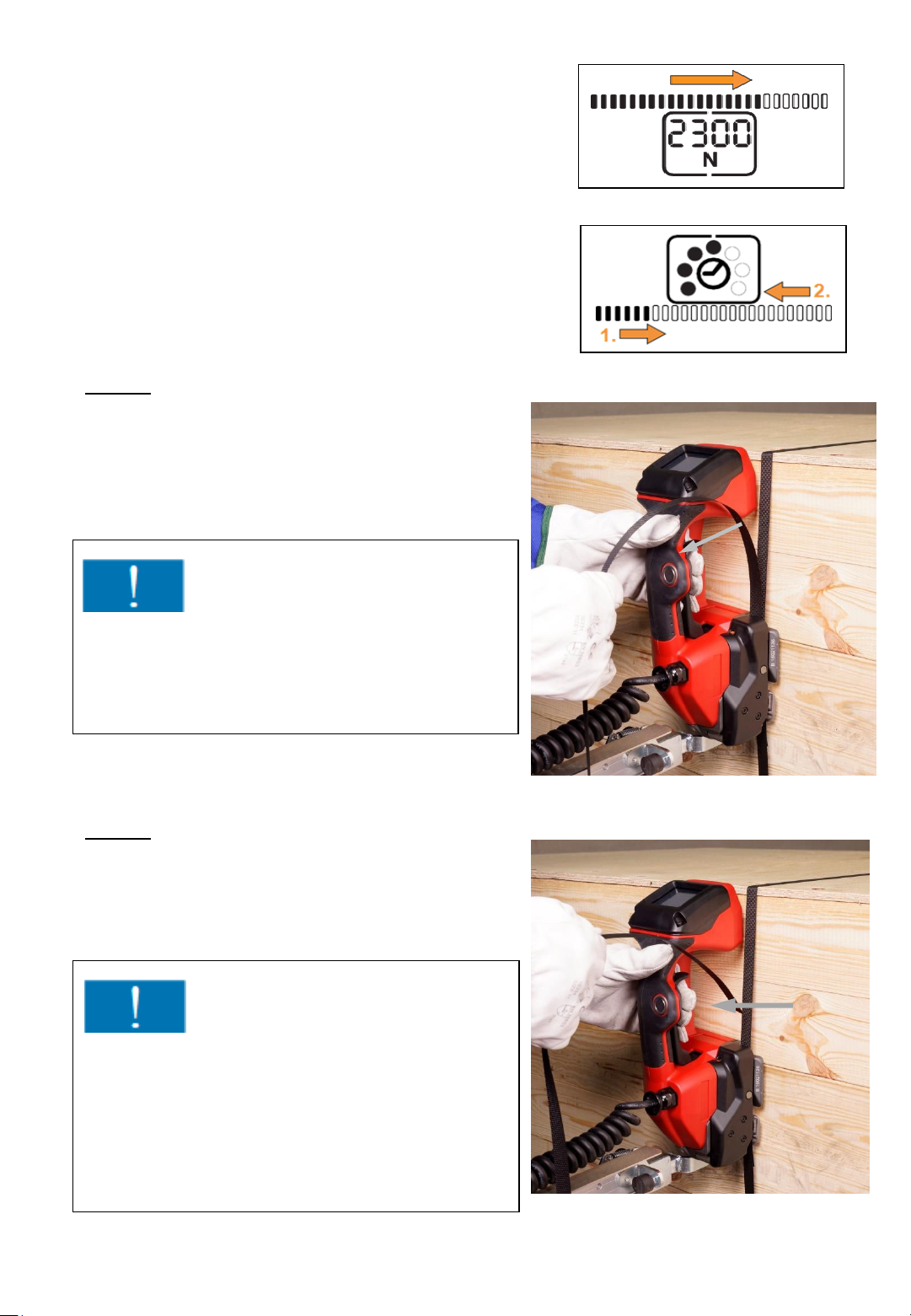
The tensioning process is finished, once
the indicator bar is filled in fully.
The welding process is finished, once the
indicator bar (1.) is filled fully.
The cool down starts (2.). After cool down there
is a beep and the display lights up green.
5. Step
As soon as the countdown is finished and
the signal has sounded you have to pull
the rocker lever towards the handle.
Attention!
If after pressing the welding button,
the welding does not start, but the sealing
head beeps, the tensioning button was not
pressed first.
Fig. 66 a
Fig. 66 b
6. Step
Now slew the sealing head to the left
while keeping the rocker lever pulled.
Attention!
It is recommended to clean the sealing
head regularly (daily), if there is a lot
of strap waste. Especially the tension wheel
and the tooth plate have to be checked for
damages and kept clean.
Please refer to point 7.8 , page 66
- 50 -
Fig. 67
Fig. 68
Page 51
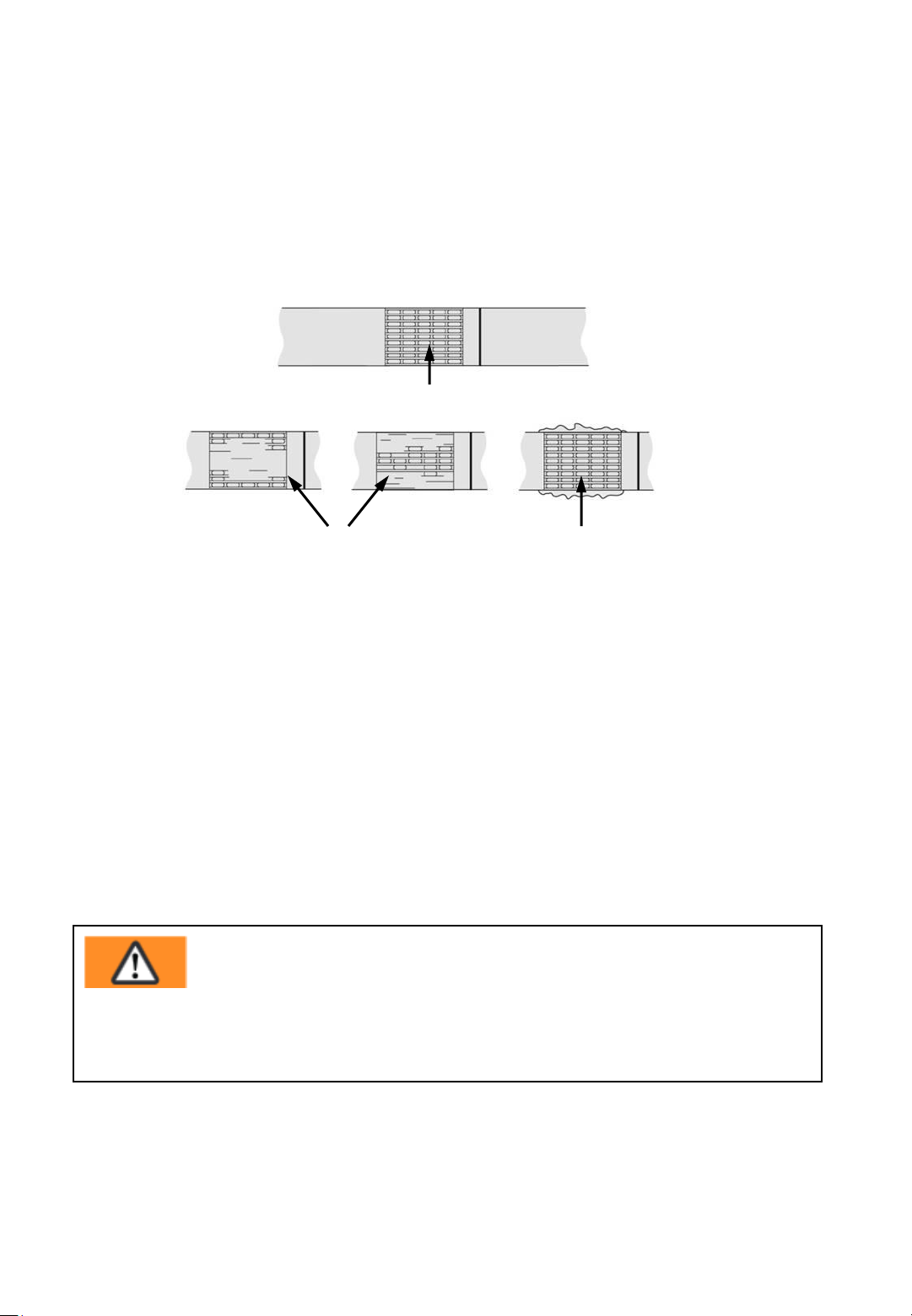
6.10 Sealing control
Control the sealing regularly. The welding time must be checked in
accordance with point 6.11 and changed if necessary when the straps are
welded badly.
1
Fig. 69
2 3
1 Good welding: the whole sealed surface has been properly welded
without any extra material being squeezed out to the side.
2 Bad welding: The surface has been unevenly welded, the selected
welding time is too short.
3 Bad welding: Surplus material has squeezed out to the side, the selected
welding time is too long.
Warning:
Improper welded straps cannot secure the loads and can therefore cause
injuries.
Never transport or move goods with improper welded straps.
- 51 -
Page 52
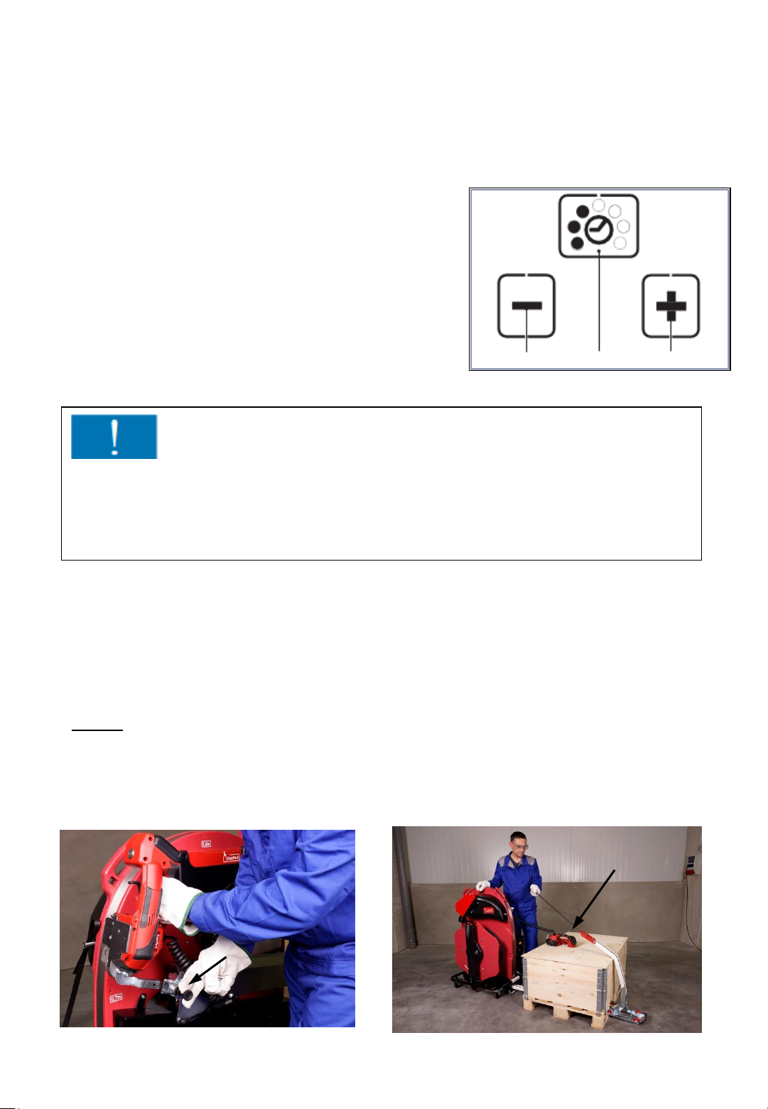
6.11 Setting the welding time
The set welding time is displayed continuously by
filled dots when the system is ready for operation.
- press Button “welding time“ (2)
• unused displays disappear.
• The filled dots of the current set welding time
flash for 5 seconds.
• + and – appear.
- press button + (1) or – (3) until the desired
welding time appears..
- Save: Press button “welding time” (2) or
wait 5 seconds.
3
Fig. 70
Important!
If the necessary welding time is between 6 or 7 to produce a good welding
according to point 6.10, there maybe a fault with the tool or worn
components in the welding mechanism. Usually both tooth plates of the
welding mechanism have to be replaced.
2
1
6.12 Tensioning and sealing of pallets below
70 cm height
1.Step
Pull out the black knob of the locking bolt. Afterwards, pull the sealing head
forward out of the holder and place it on the package to be strapped.
Fig. 71 Fig. 72
- 52 -
Page 53
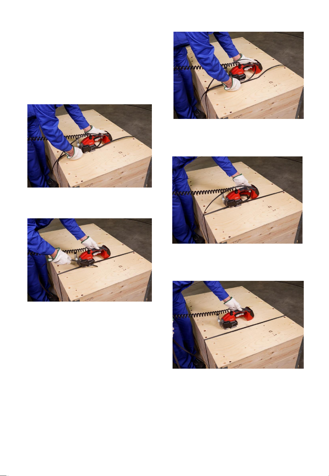
Step 1-6 proceeds exactly as
described under point 6.9,
except that the locking tool is
now in the horizontal position
(Fig 73a-e)
Fig. 73b
Fig. 73a
Fig. 73d
Fig. 73c
Fig. 73e
- 53 -
Page 54
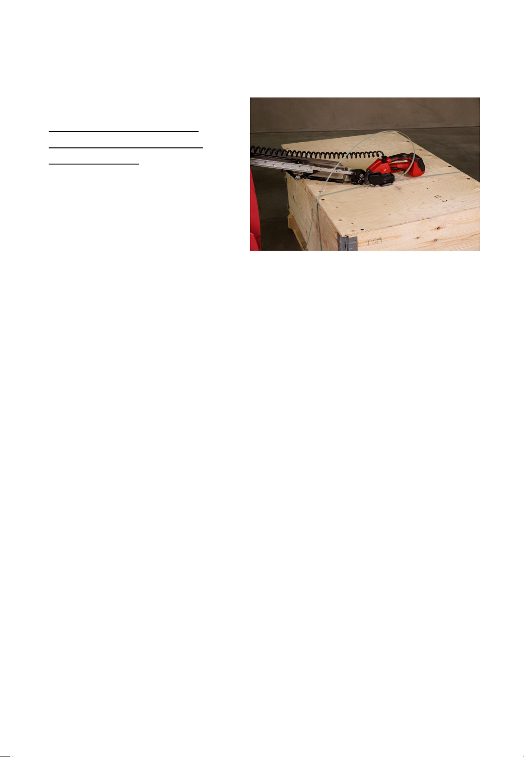
If your strapping system is
equipped with the optional
Triplex Tool-Lift:
Pull out the sealing head
horizontally, slew the sealing
head into horizontal position
and put it on top of the pallet.
Fig. 74
- 54 -
Page 55
7. Servicing and repair
Your ErgoPack is made out of galvanized steel, powder coated steel,
stainless steel and highly wear resistant plastics and is basically
maintenance free.
Clean the outside of the ErgoPack with a damp cloth if it is extremely
dirty.
Warning!
During all maintenance and service/repair works, the strapping
system has to be switched off be pressing the “OFF” switch, the
key has to be removed from the main switch and the main
power cable must be unplugged from the battery pack.
7.1 Cleaning the ChainLance
Clean the ChainLance with acetone or petroleum if it has become dirty with
oil.
Do not place the ChainLance into cleaner.
Never use lubricants like grease or oil!
- 55 -
Page 56
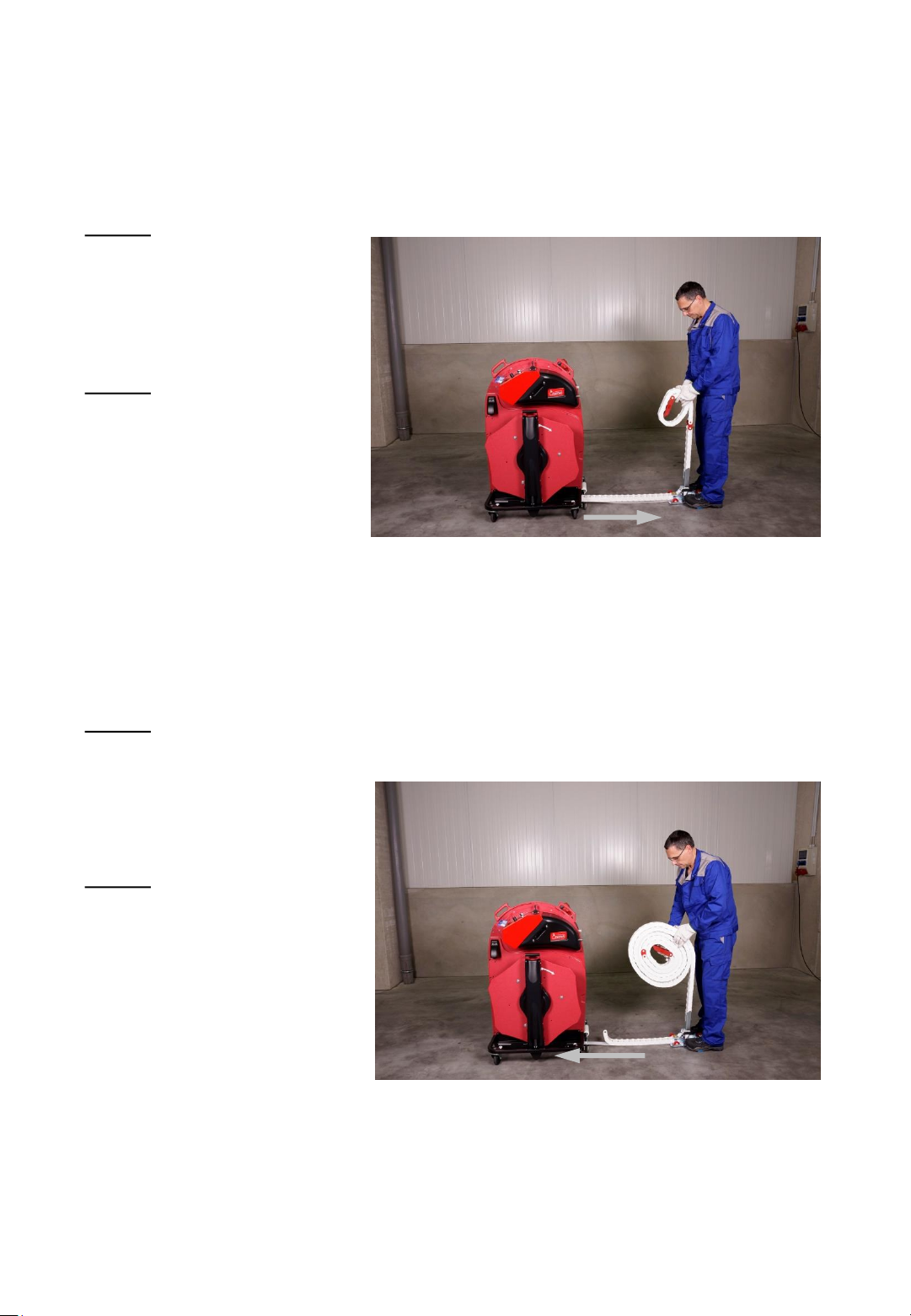
7.2 Replacing the ChainLance
1. Step
Disconnect the main
power cable from the
battery pack.
2. Step
Pull out the reversing
sledge by about 1 m,
pull out the
ChainLance of the
strapping system as
shown and roll it up.
Fig. 75
3. Step
Push the new ChainLance
in again in reversed
order of the removal.
4. Step
Reconnect the main cable
to the battery pack again,
set the main switch to
position “1“ and put the
strapping system into
operation in accordance
with point 6.2, step 2.
Fig. 76
- 56 -
Page 57

7.3 Replacing individual chain links
The ChainLance can be opened as described under point 7.4 to replace
broken chain links.
A defective chain link can also be removed without the need to insert a
new chain link. The control unit automatically adjusts to the new zero
point in accordance with point 6.2, step 2, after each restart.
- 57 -
Page 58
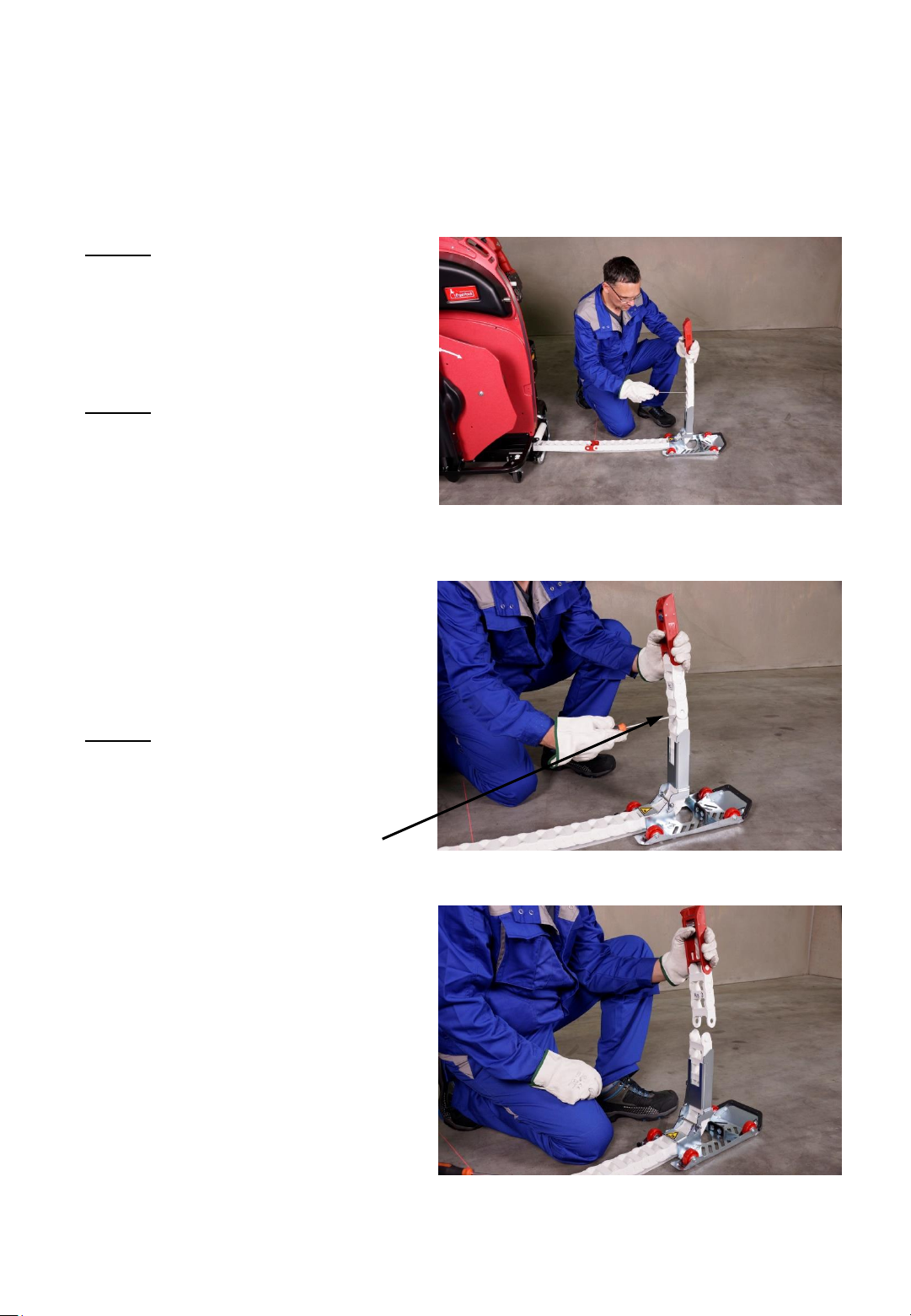
7.4 Replacing the reversing sledge
1. Step
Disconnect the main power
supply cable from the battery
pack.
2. Step
Pull the reversing sledge by
about 1 m out of the strapping
system, fold up the hinge at
the reversing sledge
and pull out approx. 60 cm of
the chain upwards as
illustrated.
3. Step
Press a screw driver between
the wings of two chain links
(there is a small groove
between the two wings to put
the screw driver to) and slew
the chain to the side until it
fully separates.
Fig. 77
Fig. 78
Fig. 79
- 58 -
Page 59
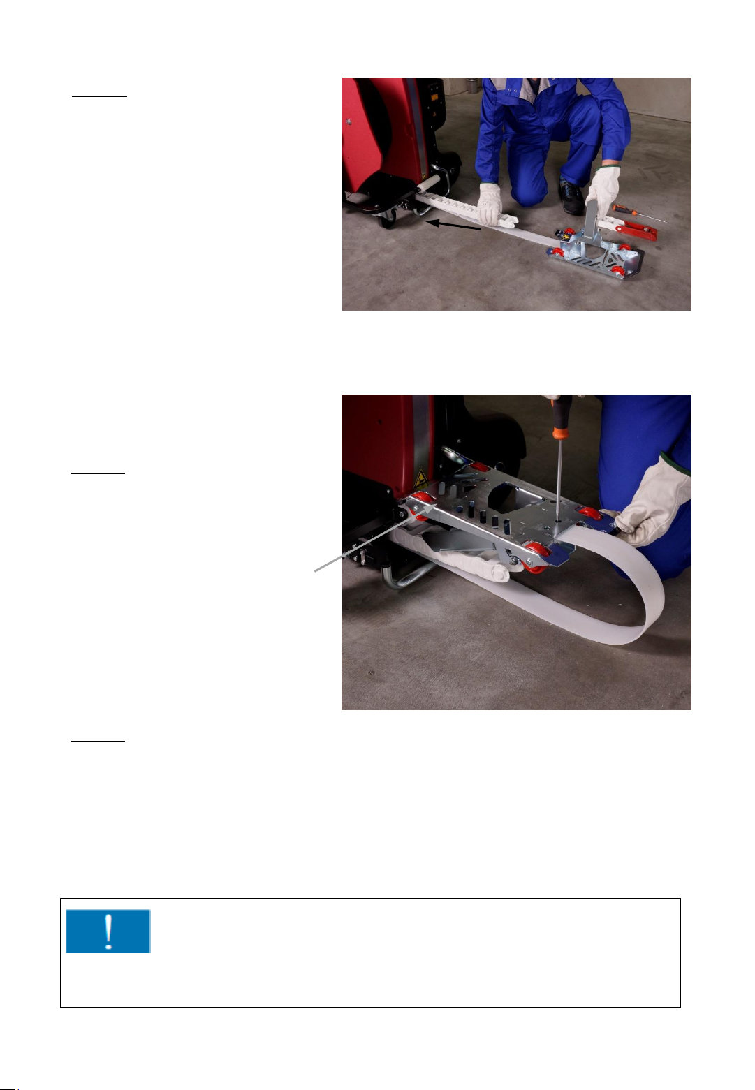
4. Step
Push the ChainLance back
into the strapping system
until it has completely moved
out of the reversing sledge.
5. Step
Place the reversing sledge on its
top as illustrated and use a
screwdriver to unscrew both
screws of the length adjusting
belt.
Fig. 80
6. Step
Fig. 81
The fitting is done in the
reversed order of the
dismantling.
Important !
Both screws of the length stop strap must be protected with screw
retaining varnish!
- 59 -
Page 60
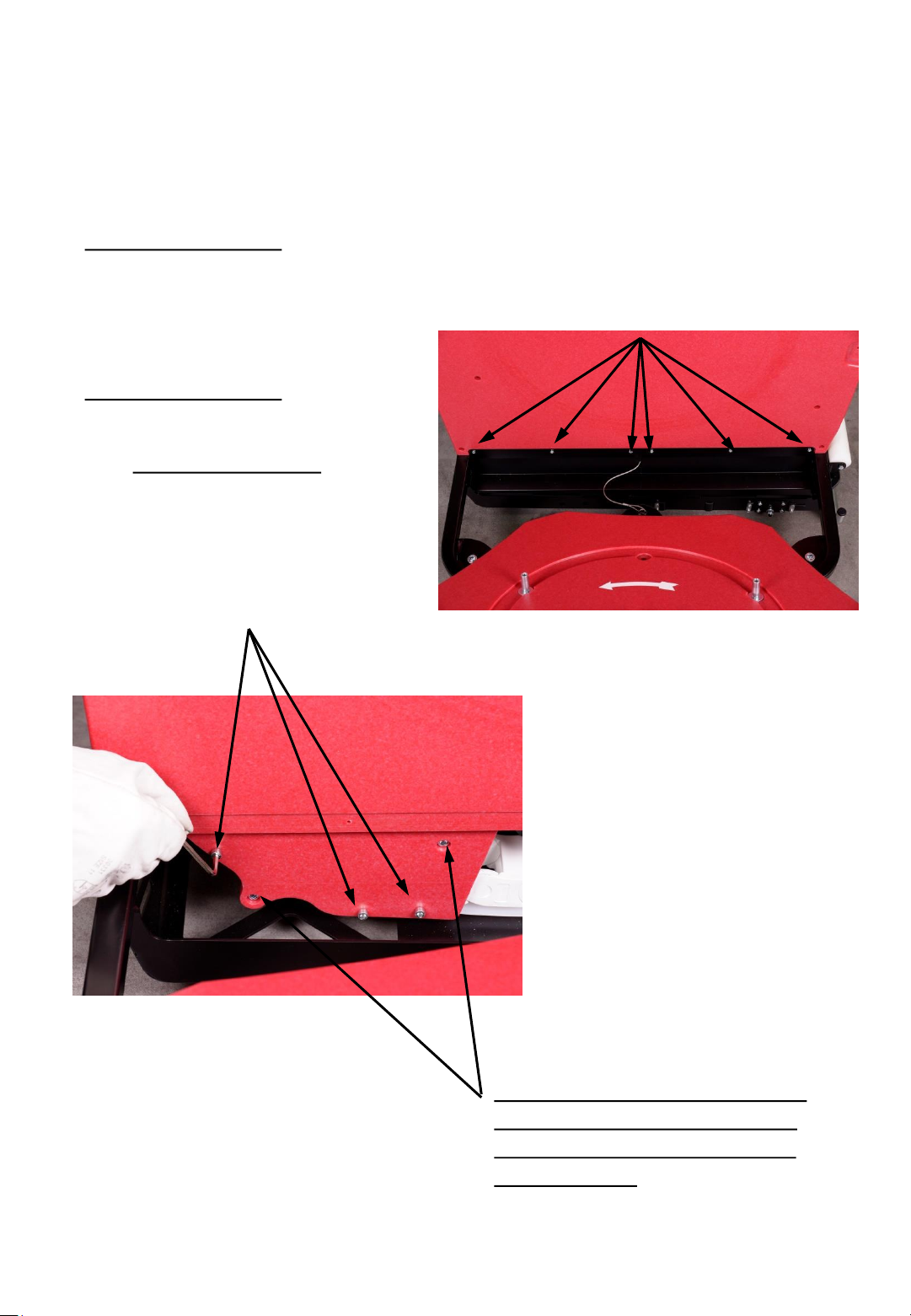
7.5 Replacing the length adjusting belt
1. Step (dismantling)
Perform steps 1 to 5 listed in point 7.4 and continue with step 2.
2. Step (dismantling)
Remove these 6 screws of the cover
with a screw driver PZ2 and
remove the two covers.
Thereafter, remove these 3 screws
(4mm allen wrench and 8mm openend wrench on opposite side.…
Fig. 83
Fig. 82
...not the hexagon socket screws
with a 5mm Allen wrench and a
10mm open end wrench on the
opposite side!)
- 60 -
Page 61
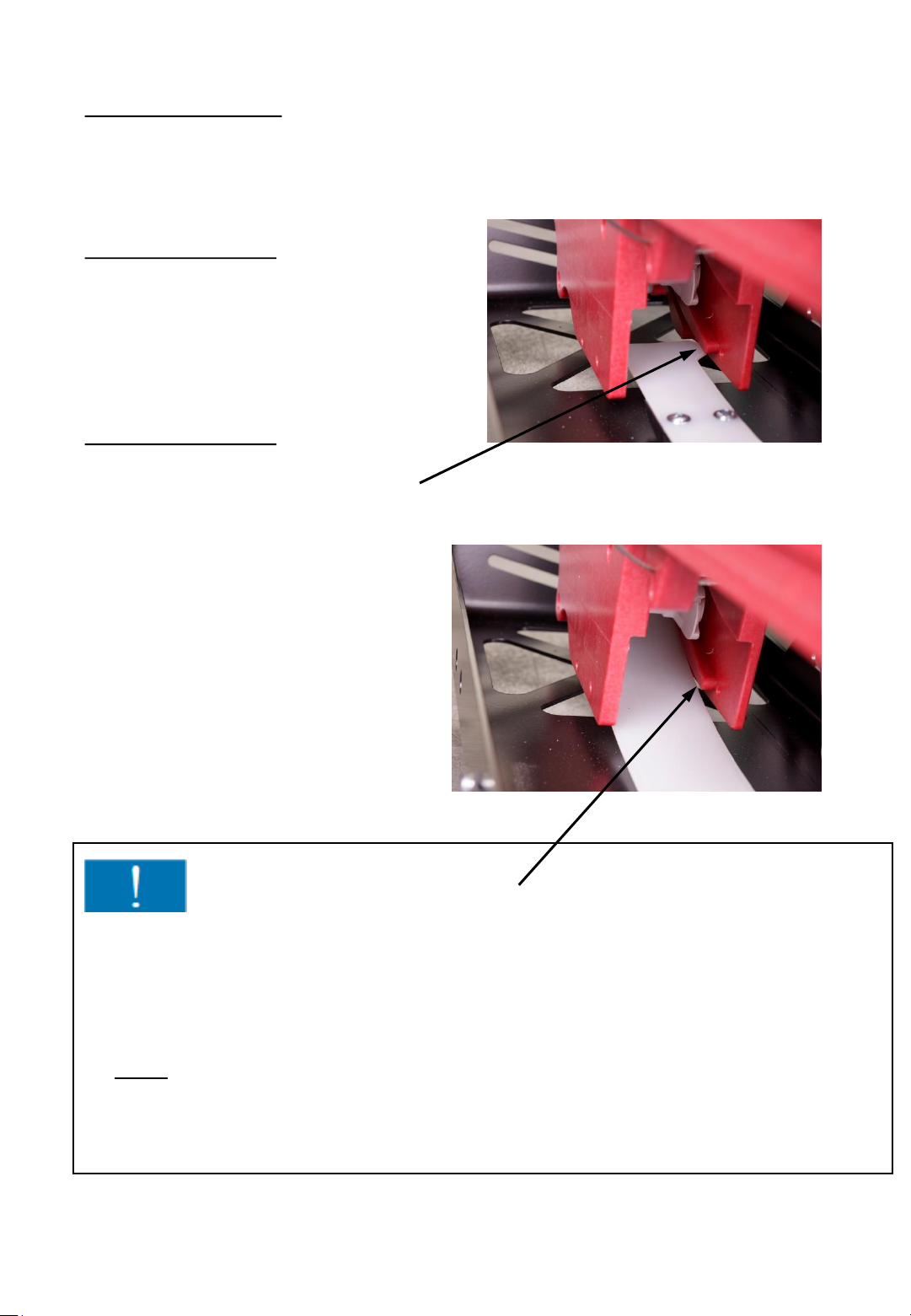
3. Step (dismantling)
Remove the pin for setting the pallet width and pull out the length
adjusting belt.
4. Step (installation)
Push the ChainLance all the way back
into the strapping system so that you can
see the groove of the length adjusting
belt.
5. Step (installation)
Fig. 84
Push the new length adjusting belt
into the small groove below the
groove for the ChainLance.
Fig. 85
Important !
Make sure that also the cut out of the length adjusting belt is inserted into the
lower groove and that it does not slide into the upper groove of the ChainLance.
Further assembling is to be done in reversed dismantling order.
The screws may only be tightened until the stop nut engages. The screws have to
be loose and must not be tightened!
If the screws have been tightened too much, the storage plates will be pressed
together, the ChainLance and the length adjusting belt could become jammed!
- 61 -
Page 62
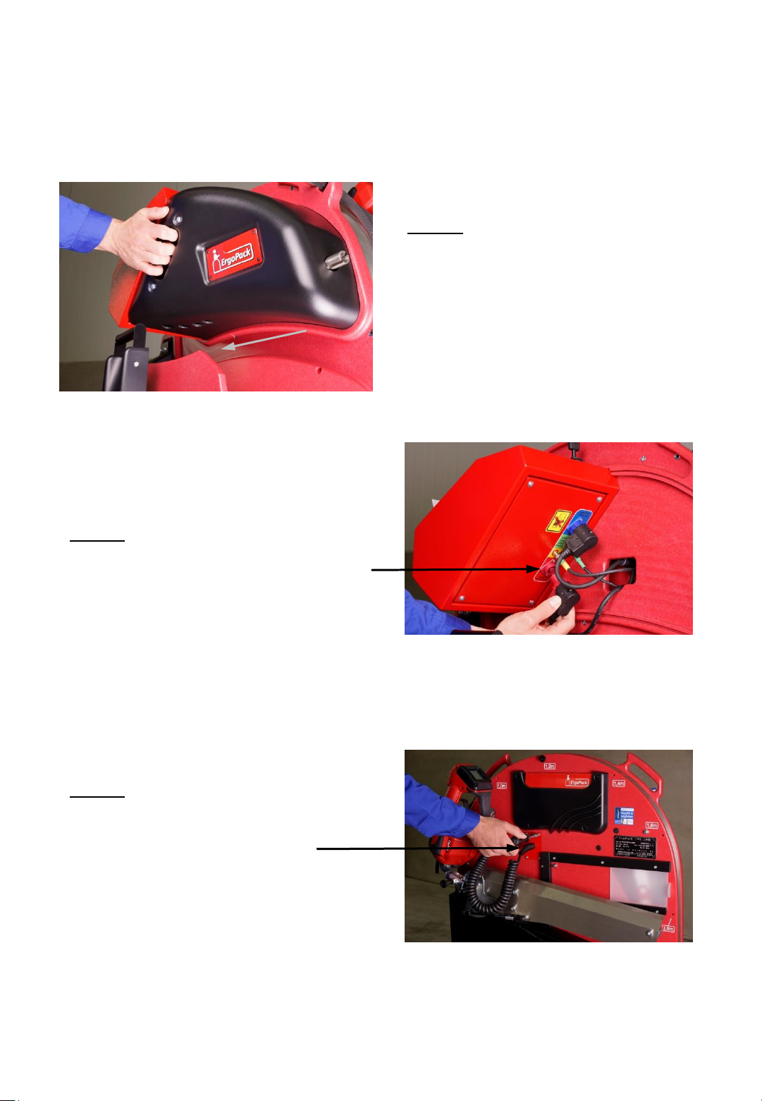
7.6 Changing the sealing head
1. Step
Remove the cover by pulling at
the handle.
(the cover is fixed by magnets).
Fig. 86
2. Step
Turn the red ring of the plug counter
clockwise and remove the red plug.
3. Step
Remove the 4 screws of the red
metal cover at the operator’s
side.
Fig. 87
- 62 -
Fig. 88
Page 63
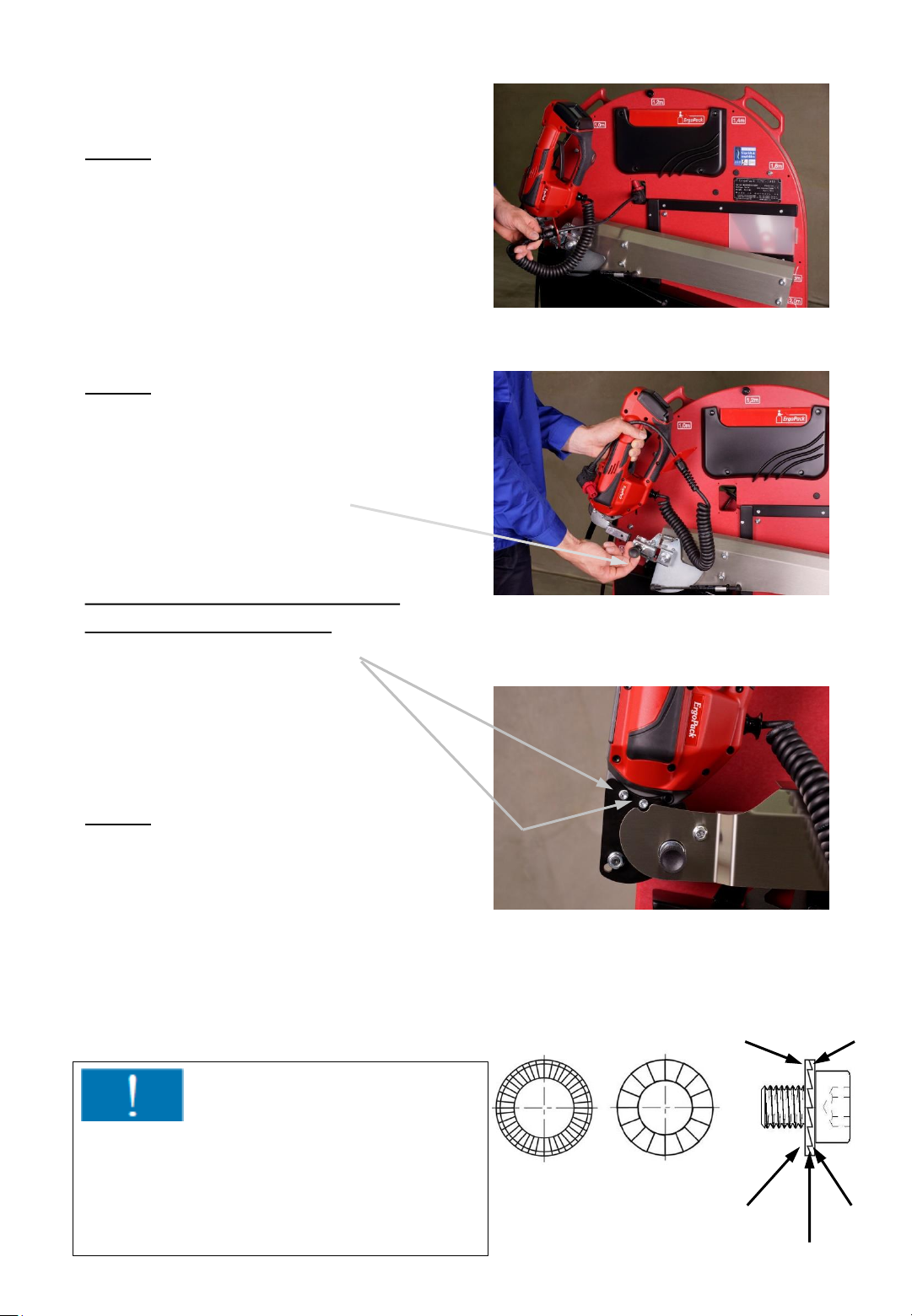
4. Step
Pull the cable with the plug through
the opening in the storage plates.
5. Step
Pull out the locking bolt for
unlocking the sealing head and
remove the sealing head.
Fig. 89
If your unit is equipped with the
optional Triplex-Tool-Lift:
Remove both screws M5 (4mm
Allen wrench). These screws
are secured with special
wedge-lock washers (The wedgelock washers can be reused).
6. Step
The mounting of the sealing head is to
be done in reversed order of the
dismantling.
When mounting the cover of the
control unit, take care to engage it first
at the level of the cutter and then all
along the groove.
Fig. 90
Fig. 91
washer 1 washer 2
When mounting the sealing head again
make sure that the rough tooth system of
the two wedge-lock washers are facing
(Fig. 92)
- 63 -
tenuous
(outward)
Fig. 92
rough
(inward)
tenuous
tenuous
rough
Page 64
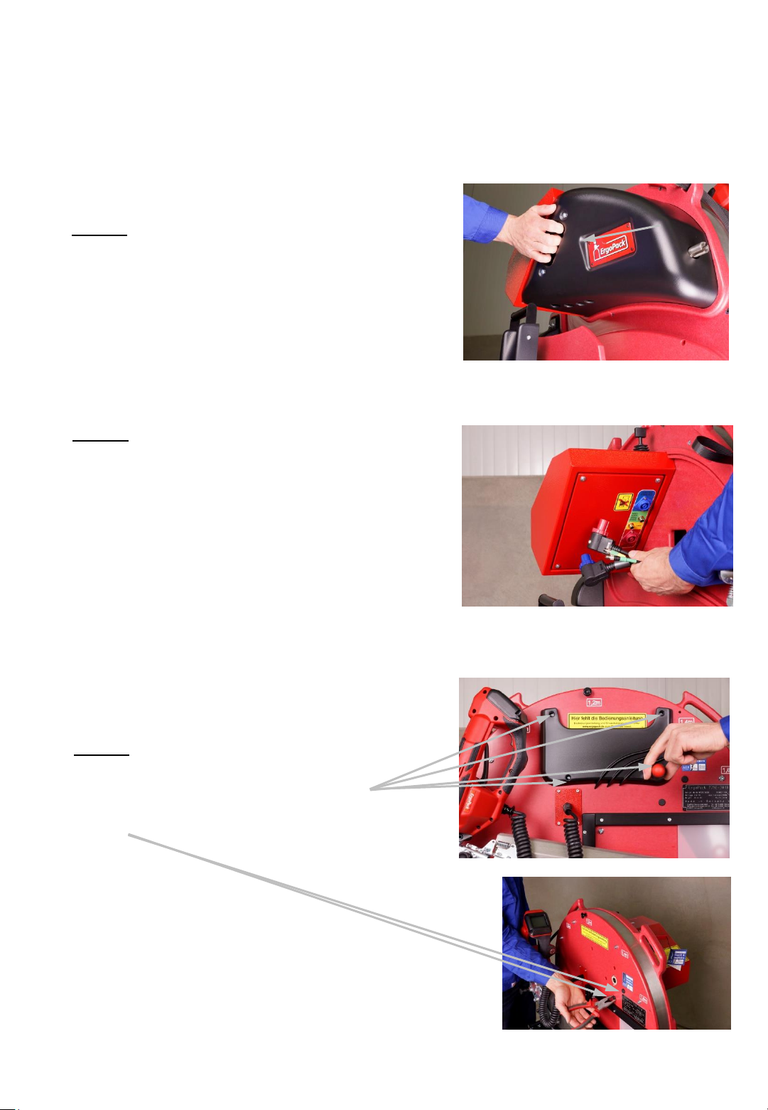
7.7 Changing the control box with the motor
1. Step
Remove the cover by pulling at
the handle.
(the cover is fixed by magnets).
Fig. 93
2. Step
Remove all three plugs on the lower
side of the control unit. (4 plugs if
optional laser is installed)
All three plugs are secured with a
safety ring which is unlocked by
turning it counterclockwise.
Fig. 94
3. Step
Remove the 4 screws of the pocket
for the manual and the 2 small cover
caps.
- 64 -
Fig. 95
Fig. 96
Page 65
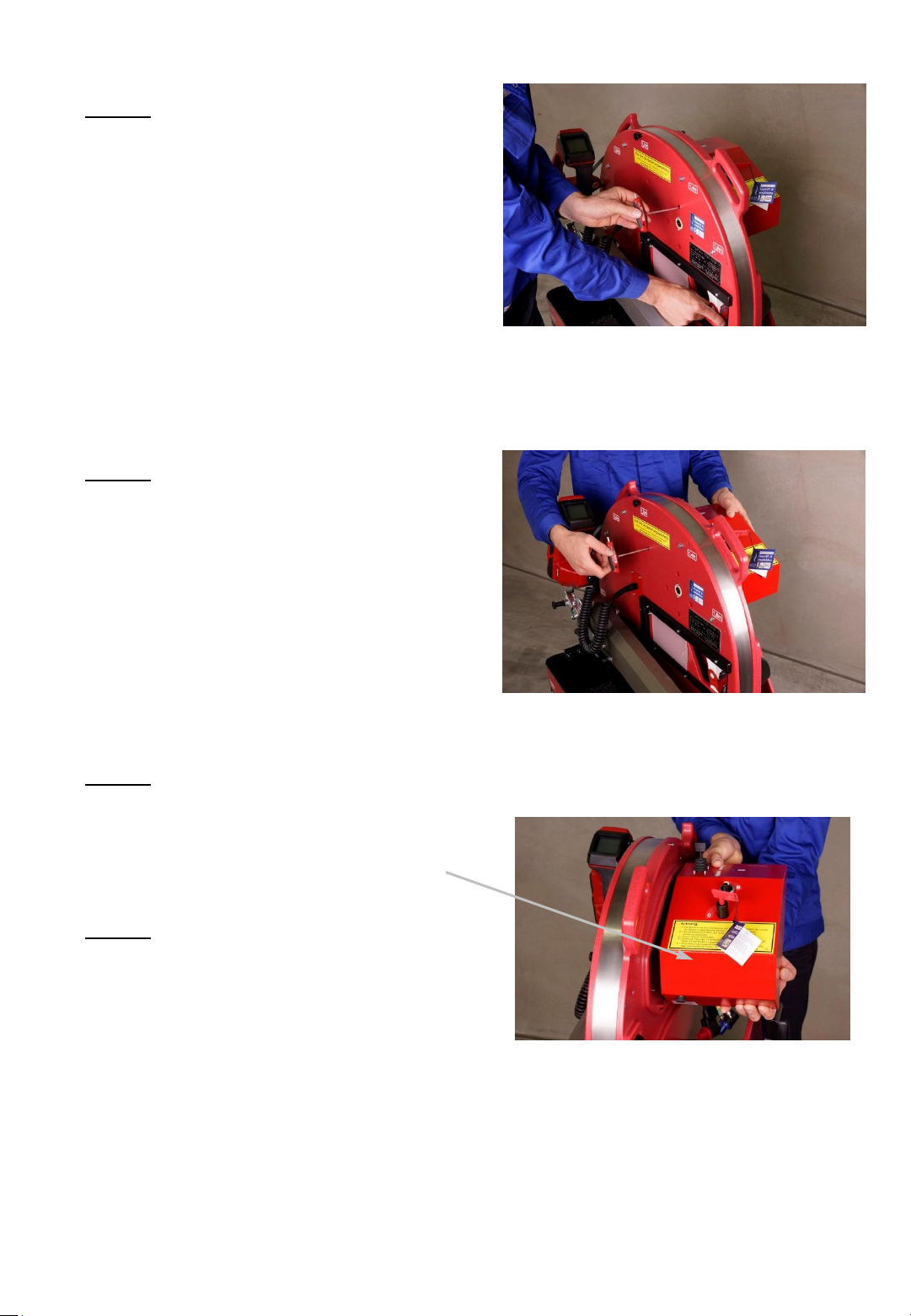
4. Step
First remove the four screws around the
drive shaft by using a 4mm Allen wrench.
To do so, you have to move the
ChainLance to turn the gear wheel until
you can see and open the individual
screws.
5. Step
Remove the fifth screw now and hold
the control unit simultaneously.
Fig. 97
6. Step
Pull off the control unit. Make sure that the
small fitting spring on the drive shaft does
not get lost.
7. Step
The installation of the control unit
is done in the reversed order of the
disassembling.
Fig. 98
Fig. 99
- 65 -
Page 66
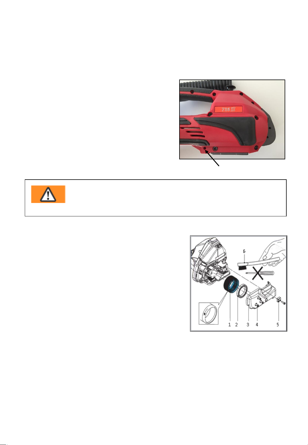
7.8 Cleaning/replacing the tensioning wheel
at the sealing head
Cleaning the tension wheel without
disassembling
There is an access hole (100a) in the
protection cover below the motor. The
tension wheel and the tooth plate can be
cleaned with compressed air through this
access hole.
When heavily soiled, the tension wheel
has to be disassembled.
Warning !
Wear eye protection when cleaning with compressed air!
Cleaning the tension wheel with
disassembling / replacing the tension wheel
Release 4 cylinder screws (Torx) (4),
remove strap guide rear (5) and side cover (3).
Remove tension wheel (1) carefully.
Remove ball bearing (2) from tension wheel.
Clean the tension wheel with compressed air.
Fig. 100
100a
If the tension wheel teeth are covered with
heavy dirt they must be cleaned carefully with the wire brush (6)
supplied.
Check tension wheel for worn teeth. If a few teeth are broken, replace
tension wheel (observe direction, see arrow).
- 66 -
Fig. 101
Page 67
Installation is done in the reversed order of the disassembling.
Grease interior gear teeth of the tension wheel lightly with Klüber grease
GBU Y 131 (Microlube).
Attention!
The tension wheel is extremely sensitive when it comes into contact with
hard, especially metallic objects. A hard object, such as a screwdriver or
similar, must not be used under any circumstances whatsoever for cleaning.
The tension wheel must not be cleaned in an installed state when it is
rotating. Risk of breakage teeth.
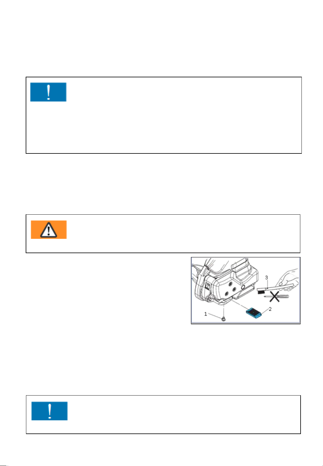
7.9 Cleaning/replacing the tooth plate at the
sealing head
Warning !
Wear eye protection when cleaning with compressed air!
Remove pan head screw (1).
Lift the rocker lever towards the handle
and remove tooth plate (2).
Clean tooth plate with compressed air.
If the tooth plate teeth are covered with
heavy dirt, they must be cleaned carefully with the wire brush supplied.
Check tooth plate for worn teeth, if necessary, replace tooth plate.
Installation is done in the reversed order of the disassembling.
Secure pan head screw (1) with screw locking varnish "medium-tight“.
Fig. 102
Attention!
The tooth plate (2) must be placed so that it can move freely in the rocker!
- 67 -
Page 68
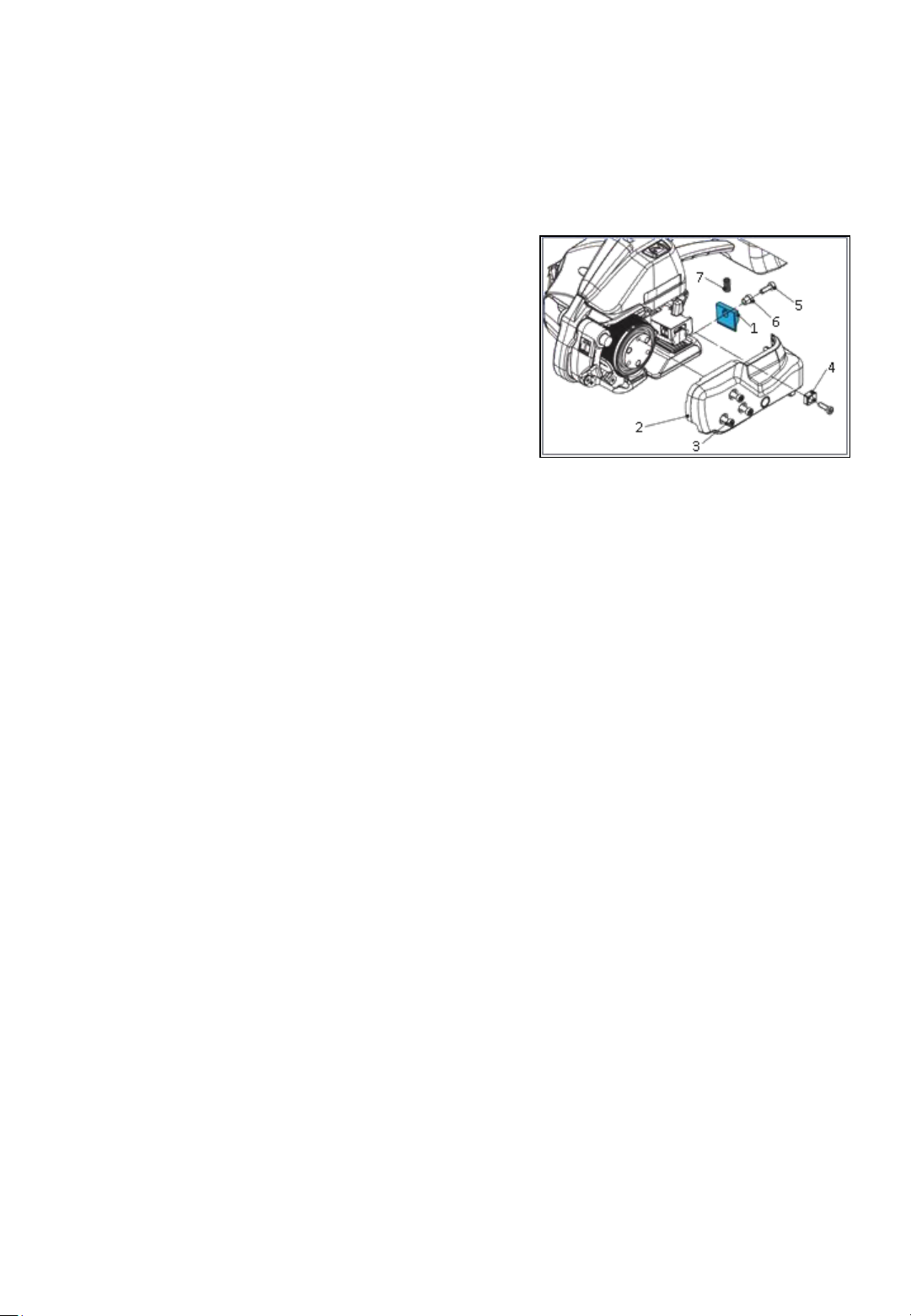
7.10 Replacing the cutter at the sealing head
Release 4 cylinder screws Torx (3),
remove strap guide rear (4) and
side cover (2).
Release cylinder screw Torx (5), take care
that you do not loose the compression
spring (7), remove knife (1) with
flanged bushing (6) and replace knife.
Installation is done in the reversed order of the disassembling.
Before installing the knife (1), check that the compression spring (7) on
top of the knife is still mounted.
Fig. 103
Secure the pan head screw (5) with screw locking varnish "medium-tight“.
- 68 -
Page 69
8. Safe moving and parking
Moving the strapping system
The strapping system can be pushed in an upright position with the two
hand grips at the head of the red frame plate. For pushing it you must
release the brakes of the two guide rolls on the strap side.
Parking the strapping system
After having parked the strapping system you have to lock up the brakes
of the two guide rolls on the strap side of the strapping system to avoid
that the strapping system is rolling away accidentally. Furthermore, you
have to make sure that the ChainLance is completely drawn in and that
the key of the main switch is removed and kept safely from the access of
unauthorized persons.
9. Spare parts lists
Spare parts lists and explosion drawings as well as the wiring plan can
be found on our website www.ergopack.de under “downloads“ as a
PDF file.
Please make a note of the type and serial number of your strapping
system for the selection of your proper spare parts list.
Please always state the number of the article when ordering spare
parts (not the position number of the part on the exploded drawing).
- 69 -
Page 70
10. General safety warnings
for power tools
WARNING! Read all safety warnings and all instructions.
Failure to follow the warnings and instructions may result in electric
shock, fire and/or serious injury.
Save all warnings and instructions for future reference.
The term “power tool” in the warnings refers to your mains-operated (corded)
power tool or battery-operated (cordless) power tool.
Work area safety
a) Keep the work area clean and well lit. Cluttered or dark areas invite
accidents.
b) Do not operate power tools in explosive atmospheres, such as in the
presence of flammable liquids, gases or dust. Power tools create sparks
which may ignite the dust or fumes.
c) Keep children and bystanders away while operating a power tool.
Distractions can cause you to lose control.
Electrical safety
a) Power tool plugs must match the outlet. Never modify the plug in any way.
Do not use any adapter plugs with earthed (grounded) power tools.
Unmodified plugs and matching outlets will reduce the risk of electric shock.
b) Avoid body contact with earthed or grounded surfaces such as pipes,
radiators, ranges and refrigerators. There is an increased risk of electric shock
if your body is earthed or grounded.
c) Do not expose power tools to rain or wet conditions. Water entering a power
tool will increase the risk of electric shock.
d) Do not abuse the cord. Never use the cord for carrying, pulling or un-
plugging the power tool. Keep the cord away from heat, oil, sharp edges or
moving parts. Damaged or entangled cords increase the risk of electric shock.
e) When operating a power tool outdoors, use an extension cord suitable for
outdoor use. Use of a cord suitable for outdoor use reduces the risk of electric
shock.
f) If operating a power tool in a damp location is unavoidable, use a residual
current device (RCD) protected supply. Use of an RCD reduces the risk of
electric shock.
- 70 -
Page 71

Personal safety
a) Stay alert, watch what you are doing and use common sense when operating
a power tool. Do not use a power tool while you are tired or under the
influence of drugs, alcohol or medication. A moment of inattention while
operating power tools may result in serious personal injury.
b) Use personal protective equipment. Always wear eye protection. Protective
equipment such as dust masks, non-skid safety shoes, hard hat, or hearing
protection used for appropriate conditions will reduce personal injuries.
c) Prevent unintentional starting. Ensure the switch is in the off-position before
connecting to the power source and/or battery pack, picking up or carrying
the tool. Carrying power tools with your finger on the switch or energising
power tools that have the switch on invites accidents.
d) Remove any adjusting key or wrench before turning the power tool on. A
wrench or a key left attached to a rotating part of the power tool may result in
personal injury.
e) Do not overreach. Keep proper footing and balance at all times. This enables
better control of the power tool in unexpected situations.
f) Dress properly. Do not wear loose clothing or jewellery. Keep your hair,
clothing and gloves away from moving parts. Loose clothes, jewellery or long
hair can be caught in moving parts.
g) If devices are provided for the connection of dust extraction and collection
facilities, ensure these are connected and properly used. Use of dust
collection can reduce dust-related hazards.
- 71 -
Page 72

Power tool use and care
a) Do not force the power tool. Use the correct power tool for your application.
The correct power tool will do the job better and safer at the rate for which it
was designed.
b) Do not use the power tool if the switch does not turn it on and off. Any
power tool that cannot be controlled with the switch is dangerous and must
be repaired.
c) Disconnect the plug from the power source and/or the battery pack from the
power tool before making any adjustments, changing accessories, or storing
power tools. Such preventive safety measures reduce the risk of starting the
power tool accidentally.
d) tore idle power tools out of the reach of children and do not allow persons
unfamiliar with the power tool or these instructions to operate the power
tool. Power tools are dangerous in the hands of untrained users.
e) Maintain power tools. Check for misalignment or binding of moving parts,
breakage of parts and any other condition that may affect the power tool’s
operation. If damaged, have the power tool repaired before use. Many
accidents are caused by poorly maintained power tools.
f) Keep cutting tools sharp and clean. Properly maintained cutting tools with
sharp cutting edges are less likely to bind and are easier to control.
g) Use the power tool, accessories and tool bits etc. in accordance with these
instructions, taking into account the working conditions and the work to be
performed. Use of the power tool for operations different from those
intended could result in a hazardous situation.
Battery tool use and care
a) Recharge only with the charger specified by the manufacturer. A charger that
is suitable for one type of battery pack may create a risk of fire when used
with another battery pack.
b) Use power tools only with specifically designated battery packs. Use of any
other battery packs may create a risk of injury and fire.
c) When the battery pack is not in use, keep it away from other metal objects,
like paper clips, coins, keys, nails, screws or other small metal objects, that
can make a connection from one terminal to another. Shorting the battery
terminals together may cause burns or a fire.
d) Under abusive conditions, liquid may be ejected from the battery; avoid
contact. If contact accidentally occurs, flush with water. If liquid contacts
eyes, additionally seek medical help. Liquid ejected from the battery may
cause irritation or burns.
- 72 -
Page 73

Service
a) Have your power tool serviced by a qualified repair person using only
identical replacement parts. This will ensure that the safety of the power tool
is maintained.
- 73 -
 Loading...