

ERGOMART LEVERLIFT Instruction Manual
LEVERLIFT
READ BEFORE INSTALLATION - SAFETY INFORMATION
INSTRUCTIONS MANUAL
©2016 All rights reserved.

LEVERLIFT
INSTRUCTIONS MANUAL
WARNING – READ FIRST
• Carefully read and understand warnings and instructions before assembly and/or
installation.
• Check all local codes and ordinances regarding mounting locations and fastening
methods.
• Local codes may supersede Ergomart instructions.
• Always retain warning statements and instructions for future reference.
• Ensure all product users read and understand the User Safety Precautions and the
instructions for safe and proper usage.
• Contact Ergomart service at 888 420 3200 with any questions prior to installation.
• Installation of this product requires basic mechanical skills and aptitudes and should
never be undertaken by someone uncertain about the terms and procedures described
in the accompanying instructions for safe use and installation.
• Use only correct tools and serviceable equipment to ensure personal safety and to
prevent damage to components, fasteners and product.
• Determine the load capacity of the wall, ceiling, member, surface or structure you intend
to use before installation. Consult a professional installer, Ergomart technical support
or an engineer if the material to which you plan to attach is not specifically described
in the installation manual.
• Never alter products or assemble in a fashion not described within the instructions
without consulting an installation professional, engineer or Ergomart technical support
at 888 420 3200.
• Never exceed the Maximum Load for any device or component. If you are unsure about
any weight rating on any given component within a modular system provided by Ergomart,
contact Ergomart service at 888 420 3200.
• Never introduce or add additional components into an existing modular system without
consulting Ergomart technical support at 888 420 3200.
• Never attempt to open, service or disassemble any Ergomart component where no
written Ergomart instructions are available for disassembly and repair.
• Never use harsh chemicals or abrasives to clean Ergomart products. Use mild, dilute
cleaners and test before widespread use on an inconspicuous location or surface.
• Use best practices before and during installation:
o Always use the correct tool for the specified procedure or job.
o Always use assistance and lifting devices wherever indicated within the
instructions.
o Avoid shortcuts and always measure twice before drilling, cutting or changing
things that cannot be altered.
o When penetrating walls or surfaces, determine that no wiring, gas, ductwork or
plumbing exist beneath the surface.
o Consult an installation professional, facility manager or engineer before starting
an installation project involving materials with properties that are not evident
from experience or described as acceptable medium for attachment within the
Ergomart documentation.
1
©2016 All rights reserved.

LEVERLIFT
INSTRUCTIONS MANUAL
DISCLAIMER
Ergotect Corporation and its subsidiaries and brands, hereafter referred to as (EC), strive
to create broadly comprehensible, complete and accurate information regarding our product installation documentation. Ongoing changes in suppliers, materials, designs, components, product upgrades, and other variables inhibit our ability to guarantee document
accuracy. Furthermore, EC reserves the right to make changes and updates to product
documentation and/or product design without notifying existing and new users. EC therefore does not guarantee completeness, accuracy or suitability of documentation and will
not be held liable due to incomplete documentation, editorial errors, improper translation
from English, or the comprehensibility of language or images or the ability of a user to
understand any particular written instructions or interpret images contained herein and
below.
EC disclaims any liability for damage to EC provided product, customer or user owned
devices and equipment affixed to, used on or in conjunction with EC provided product,
other property, or personal injury resulting, in whole or in part, from improper installation,
modification, use or misuse of its products. EC disclaims all other warranties, express or
implied, including warranties of merchantability and fitness for a particular purpose. EC
is not responsible for incidental, special or consequential damages, including but not limited to, inability to use EC products or costs incidental to the installation or removal of
defective or serviceable EC products or components.
2
©2016 All rights reserved.
LEVERLIFT
INSTRUCTIONS MANUAL
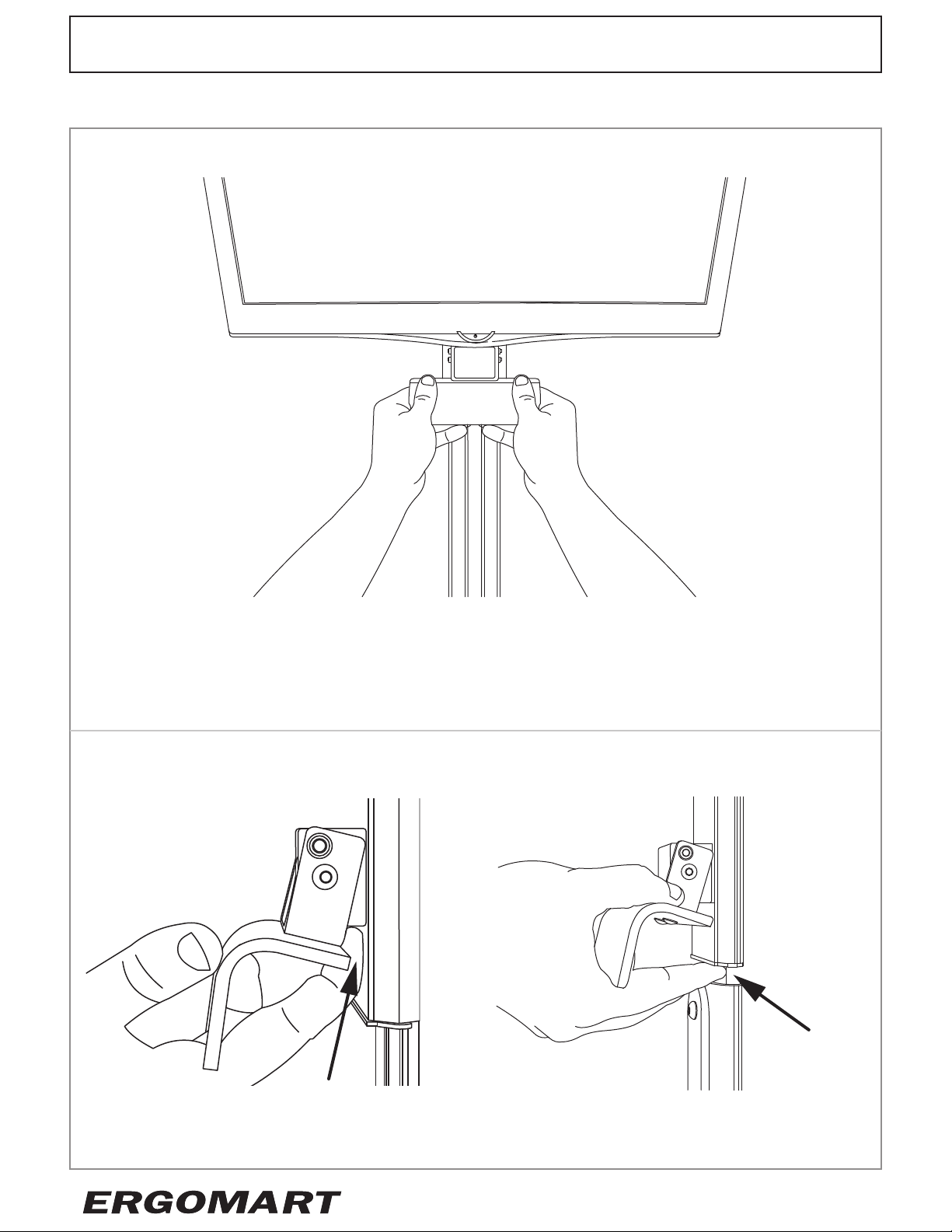
LEVERLIFT USER SAFETY PRECAUTIONS
OPERATE LEVER WITH BOTH HANDS
To raise or lower a LeverLift, grasp with both hands as illustrated and pull up slightly to
release the brake. Once disengaged, the device may be lifted up to raise the height or
allowed to slide down to a lower position. Once the desired height is achieved, release the
handle. Returning the handle to the rested position causes the LeverLift mechanism to
brake immediately and securely.
AVOID PINCH POINTS
PINCH POINT
PINCH POINT
Always use two hands to raise and lower the LeverLift to avoid pinch points.
3
©2016 All rights reserved.

LEVERLIFT
INSTRUCTIONS MANUAL
LEVERLIFT USER SAFETY PRECAUTIONS (Continued)
• Do not remove safety and warning labels and stickers from the LeverLift System.
• Always use two hands when lifting or lowering monitors, touch screens or any heavy
component.
• The LeverLift is suitable for use by individuals who have a full range of motion and use
of both hands and both arms and are able to lift 20 lb above the head using both hands
simultaneously. Not all individuals will be able to move components vertically and may
require assistance.
• Maximum payload per LeverLift is 12 lb (5.4 kg).
• All users must receive instruction on the safe and correct, two handed
method of lifting and lowering loaded LeverLift mechanism.
• This product is intended for users age 18 and above.
• This product is intended for indoor use.
• Keep fingers and hands away from pinch points.
ATTENTION:
MAKE OPERATING INSTRUCTIONS AVAILABLE TO ALL LEVERLIFT OPERATORS.
4
©2016 All rights reserved.

LEVERLIFT
INSTRUCTIONS MANUAL
M-TRACK INSTALLATION AND INSTALLER SAFETY OVERVIEW
• Pre-Installation Preparation:
o Clear installation space of clutter and items that could create a hazardous work area.
o Remove end stops and any other components that are attached to the track.
o Determine the optimal vertical position of the rail and the correct fastener components
for the surface using the tables in Appendix A. Select the appropriate table for
your application.
o It is critical that the dimensions of all LeverLift components and devices be known
and taken into consideration before installation to eliminate interference.
o When mounting any type of wall track to a wall it is always best practice to affix it
into a wood stud or backer. The LeverLift System and M-Track, however, is designed
to work where an immovable support structure is unavailable.
o C
walkways, furniture, fixtures, and electrical panels are some of many potential
obstructions and hazards.
o Make note of wire management needs such as locations of networking ports and
outlets so that device wiring does not cause interference.
heck for operational clearance for all components and users. Doors, adjacent walls,
• Unbacked Sheetrock:
o Sheetrock must be 1/2” or thicker and must be serviceable. The age, condition, and
capacity of the sheetrock must be considered. Inspect fasteners for secureness and
o Snaptoggle® BA-10-24 will be used with 3/16”-24 machine screw fasteners.
o Ensure that sheetrock is correctly attached to the framing/structure with sufficient
fasteners connected at properly spaced intervals.
o Ensure that sheetrock is not warped or bent as it may cause bowing or bending of
the Leverlift track leading to difficult slider use. For minor deviations of flatness
of less than .25” use shims available from Ergomart.
• Sheetrock backed with a thin gage metal stud:
o Sheetrock must be at least 1/2” and serviceable. The age, condition, and capacity
of the sheetrock must be considered. Inspect fasteners for secureness and sheet rock for integrity initially and on a periodic basis once the track has been installed.
o Snaptoggle® brand BA-10-24 will be used with 3/16”-24 machine screw fasteners.
o Ensure that sheetrock is not warped or bent as it may cause bowing or bending of
the Leverlift track leading to difficult slider use. For minor deviations of flatness
of less than .25” use shims available from Ergomart.
sheetrock for integrity initially and on a periodic basis once the track has been
installed.
• Sheetrock that is directly backed with a wood stud:
o Stud must be in good condition.
o Pre-drill fastener locations with 3/32” pilot holes to prevent splitting the stud.
o Ensure that sheetrock is not warped or bent as it may cause bowing or bending of
the Leverlift track leading to difficult slider use. For minor deviations of flatness
of less than .25” use shims available from Ergomart.
5
©2016 All rights reserved.

LEVERLIFT
INSTRUCTIONS MANUAL
M-TRACK INSTALLATION AND INSTALLER SAFETY OVERVIEW (Continued)
• The LeverLift track may be affixed to a variety of additional surfaces including CMU,
metal, masonry bricks, and concrete as well as many piers and poles. Work
with an installation professional or other qualified person to determine the best
attachment method for your specific application.
• Other materials and substrates require specific solutions. Due to the abundance of wall
materials and building methods, Ergomart can only specifically recommend attachment
methods for the above described conditions. In all other instances, determine the correct
fastener for the job and if you are unsure, consult with a professional installer, home
improvement store specialist or engineer. Prior to installation, ensure the surface,
material, structure or member you wish to use for fixing will support the entire payload.
ADDRESSING WALL FLATNESS ISSUES WITH SHIMS
Suitable wall mount locations must be generally flat and uniform surfaces.
Irregularities will hinder the correct installation of the M-Track and result in
difficult operation of LeverLift Sliders. Conditions with irregularities that may or
may not be correctable with shims:
o Wall joints that do not abut flatly and cleanly
o Surfaces that are bowed or warped
o Surfaces that have bulges or crowns
o Sheet rock improperly installed or not attached to stud
o Wall materials or surfaces that are not rigid
• The Leverlift is designed for use with surfaces that are flat over the length of the
mounting area beneath the track. Before purchasing the Leverlift system utilize a straight
edge that spans the intended mounting location. Surfaces with minor depressions or
bumps will require shims. Surfaces with bulges or crowns that are greater than .25” are
not suitable for the LeverLift System. Surfaces with valleys or depressions greater than
.25” are also not suitable for the Leverlift system. Experienced Installers may use various
techniques to correct an irregular surface.
• If you are currently installing your M-Track and have discovered you require shims,
you may fashion shims using poster board and sizing them into 2” x 3.5” pieces and then
stacking them into the appropriate thickness.
LEVERLIFT COMPONENT INSTALLATION SEQUENCE
When installing your M-Track and LeverLift, always ensure the M-Track is properly and
securely attached to the wall before installing any LeverLift or other components. Install
components from the bottom of the track, starting with the item that will ultimately rest
at the top of the track. Ensure sliders with set screws are tightly secured before installing
devices. Begin installing devices with thin clients/CPUs first where applicable, followed by
monitors, wire managers, keyboards, mice, and any other peripherals. Finish your installation by inspecting your components/devices for possible errors during installation. If no
error is found, reattach M-Track end caps.
6
©2016 All rights reserved.
LEVERLIFT
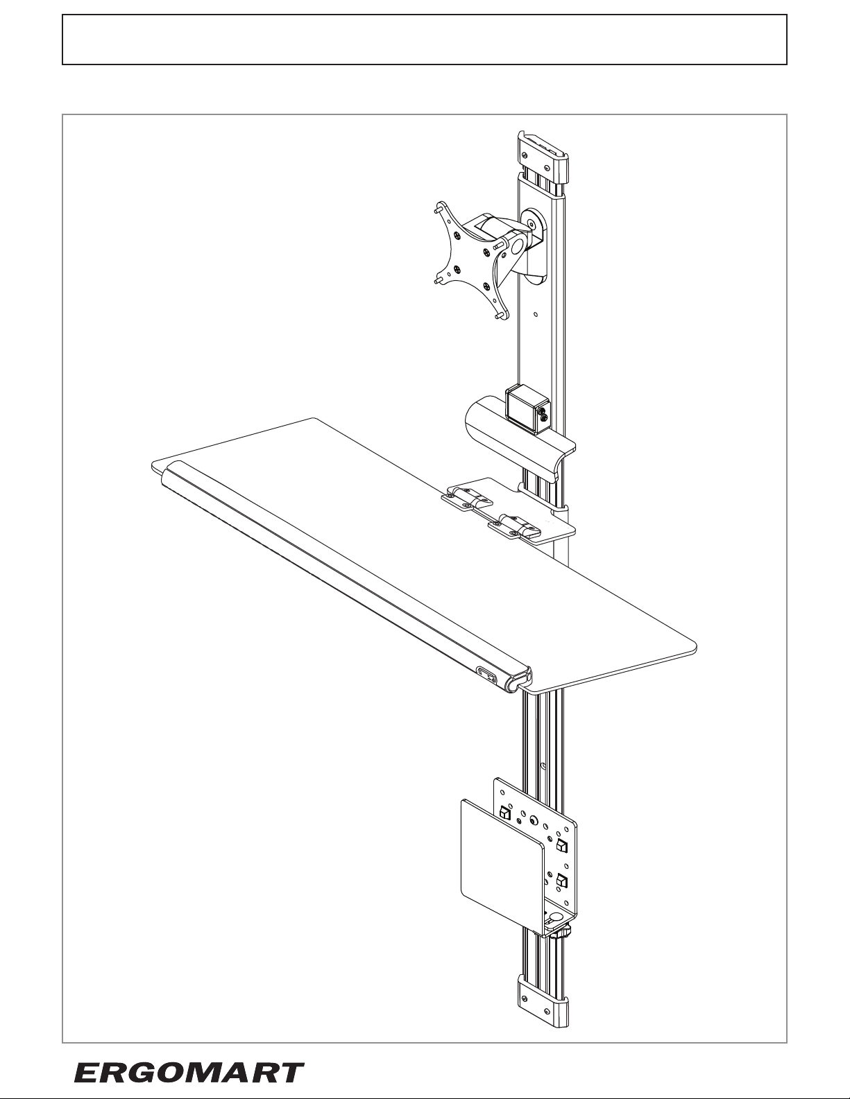
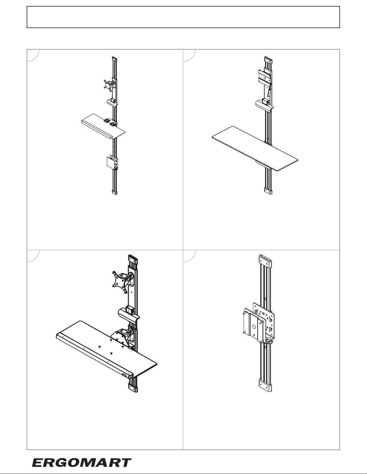
SAMPLE CONFIGURATIONS
1 2
INSTRUCTIONS MANUAL
75/100mm VESA with Articulating Mount
on 14” low profile LeverLift and 26” Folding
Keyboard LeverLift with a Thin Client Bracket
on 77” M-Track.
3 4
26” Fixed Tray LeverLift and 14” Low Profile
VESA 100 LeverLift on 51” M-Track.
75/100mm VESA with Articulating Mount on
14” low profile LeverLift and an Articulating
20” Keyboard Tray LeverLift on 39” M-Track.
Rotating 100mm VESA Slider Plate mounted
in front of a Thin Client Bracket on 27” MTrack.
7
©2016 All rights reserved.

LEVERLIFT
ASSEMBLY INSTRUCTIONS:
SECTION 1 | TRACK INSTALLATION: RIGIDLY BACKED/HOMOGENEOUS SURFACES
SECTION 2 | TRACK INSTALLATION: SHEETROCK AND/OR METAL STUD
SECTION 3 | LEVERLIFT COMPONENT INSTALLATION
SECTION 4 | LOW PROFILE QUICK RELEASE INSTALLATION
SECTION 5 | ARTICULATING MOUNT INSTALLATION
SECTION 6 | PLAIN THIN CLIENT HOLDER INSTALLATION
SECTION 7 | THIN CLIENT HOLDER WITH VESA PLATE INSTALLATION
INSTRUCTIONS MANUAL
SECTION 8 | FIXED KEYBOARD TRAY INSTALLATION
SECTION 9 | FIXED SHELF INSTALLATION
SECTION 10 | FOLDING KEYBOARD TRAY INSTALLATION
SECTION 11 | WIRE MANAGER INSTALLATION
TOOL KIT
These items will typically be needed for correct installation:
• Pencil
• Level
• Cordless power drill with appropriate driver bits (Phillips, square, etc.)
• Drill bit set
• Mallet (soft)
• Tape measure
• Ladder or stepstool
• Adequate lighting
• Safety goggles
• Stud finder
• Appropriate Fasteners (Snap toggles, #10 wood screws, etc.)
• Assistant
8
©2016 All rights reserved.
LEVERLIFT
INSTRUCTIONS MANUAL
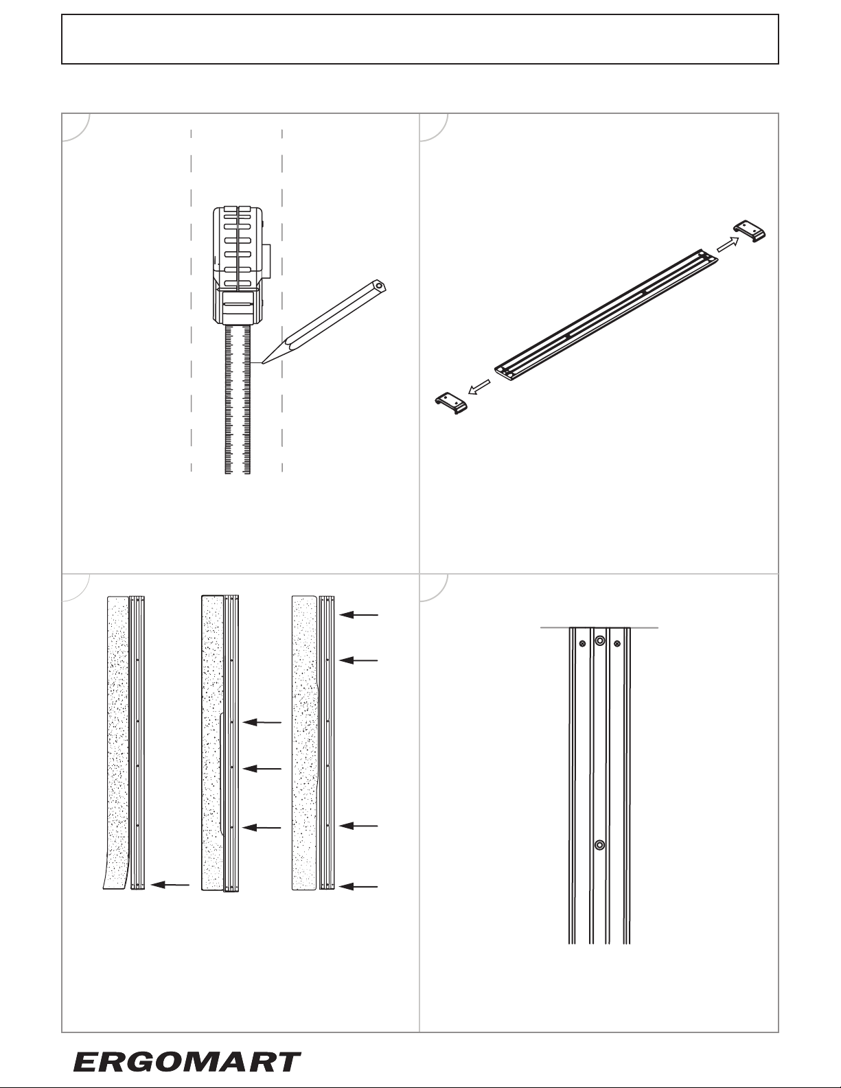
SECTION 1 | M-TRACK INSTALLATION: RIGIDLY BACKED/HOMOGENEOUS SURFACES
1.1 1.2
Determine location and height of track in
front of stud. Consult tables on page 28 for
vertical placement and mark the location of
the top of the track.
1.3 1.4
Remove end stops by loosening set screws
and sliding them off the track.
WARNING: Inspect location for flatness. If
a credit card easily slides beneath any point
under the edge of the track proceed to
Appendix B on page 29, do not proceed
onward to 1.4.
Align the top of the track with the location
marking from Step 1.
9
©2016 All rights reserved.
 Loading...