

Page 1
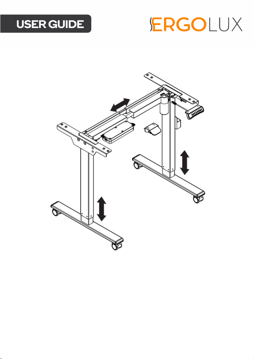
WHITE BOARD AND
STANDING DESK
ELSTANDWWBA
Page 2

Page 3

• Read all instructions before use and retain this user guide for future reference.
• Read all following safety precautions carefully before use.
• Yo ur e qu i p me n t is i nt e n de d fo r us e i n c o ol , d ry c o nd i t io n s . Yo u sh o u ld a vo i d st o ra g e
in extreme cold, hot or damp areas as this may lead to corrosion and other related
problems. Operating temperature 0-40°C
• If the power cord is damaged, cease use immediately and contact Kogan.com for
support.
• Unplug the power cord before cleaning. Wipe the dust from the surface using a
slightly damp cloth. Ensure any water does not come in contact with any internal
parts or connectors.
• Do not use any corrosive or abrasive materials to clean the product.
• The control box contains electronic components, metals, plastics, wires etc. ensure
it is disposed of in accordance with your local environmental legislation. Do not
dispose with general household waste.
• Ensure this product is completely and correctly assembled before use.
• Be familiar with all functions and program settings of the product before first use.
• The desk will emit a slight noise caused by the V-ribbed belt or brake system. This
is completely normal and will not affect the product’s operation or performance.
• This product can be used by children aged from 8 years and above and persons
with reduced physical, sensory or mental capabilities or lack of experience and
knowledge if they have been given supervision or instruction concerning use of the
appliance in a safe way and understand the hazards involved.
• Children should not be allowed play with this product.
• Cleaning and user maintenance should not be performed by children without
supervision.
• Retain the original packaging where possible, to use for any future transportation of
this product.
Page 4
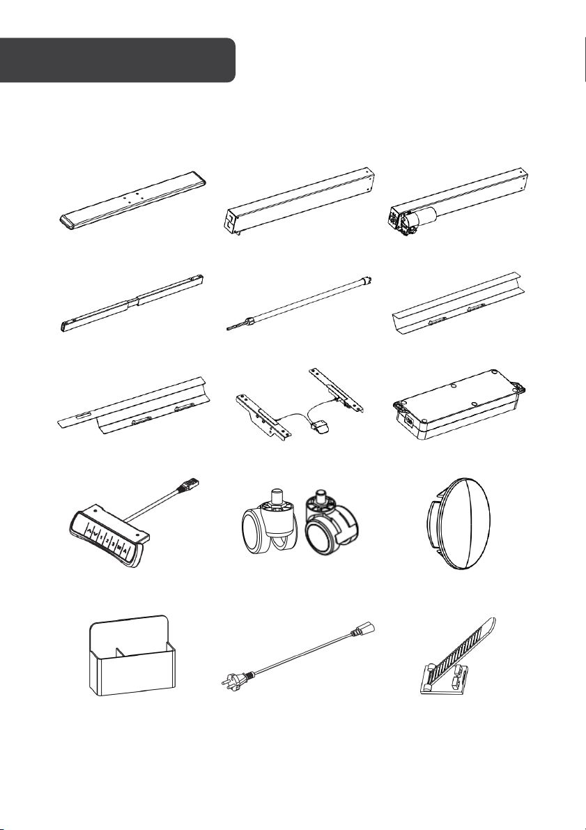
1 Fee t (x2)
2 Left lifting column
3 Right lifting column
4 Supporting beam
5 Tra n s m i s s i o n rod
6 Left baffle
7 Right baffle
8 Side brackets (pair)
9 Control box
10 Handset
11 Castor with brake (x2)
Castor (x2)
12 Screw cover (x4)
13 Storage box
14 Power cord
15 Cable tie (x8)
COMPONENTS
Lay all components out on a clean floor and ensure all parts are included. If any pieces are
missing, check all packaging thoroughly, then contact help.Kogan.com for assistance.
Page 5
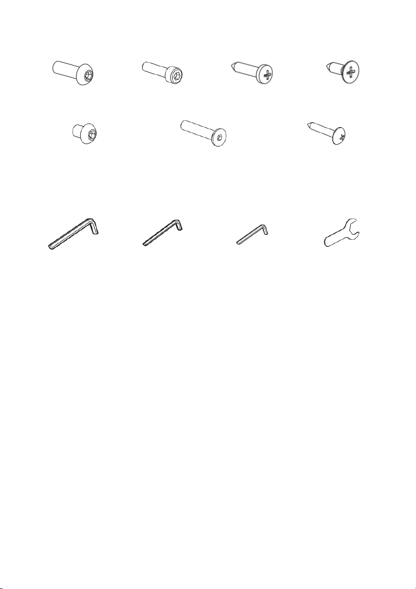
Hardware list
A M6 (x8)
B M6 (x4)
C Self-tapping
screw (x4)
D Self-tapping
screw (x8)
E M4 (x4)
F M8 (x4)
G Self-tapping screw (x10)
5mm Allen key
4mm Allen key
2.5mm Allen key
Spanner
To o l s
Page 6
A M6 (x8)
4mm Allen key
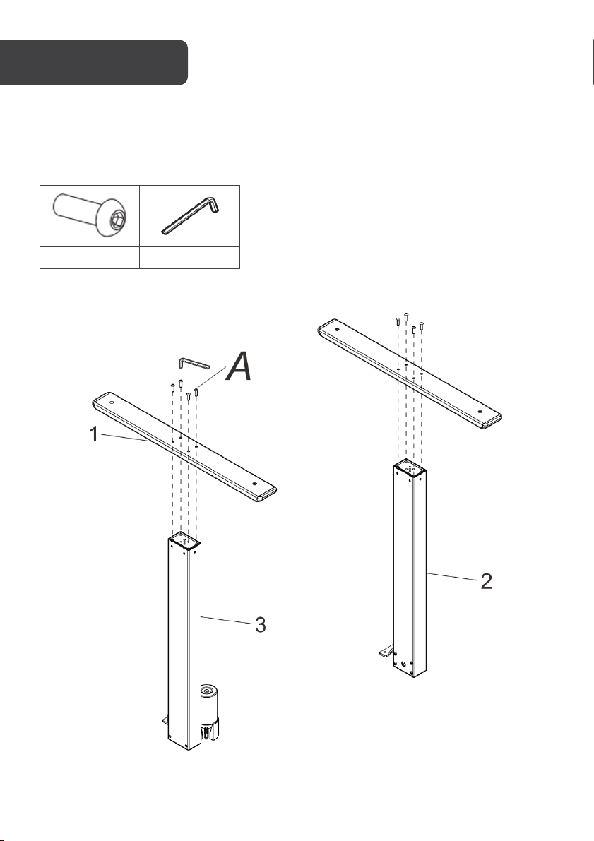
Step 1: Installing the feet.
Attach the feet (1) to the lifting columns (2)(3) using the M6 screws (C) and tighten using the
4mm Allen key.
Page 7
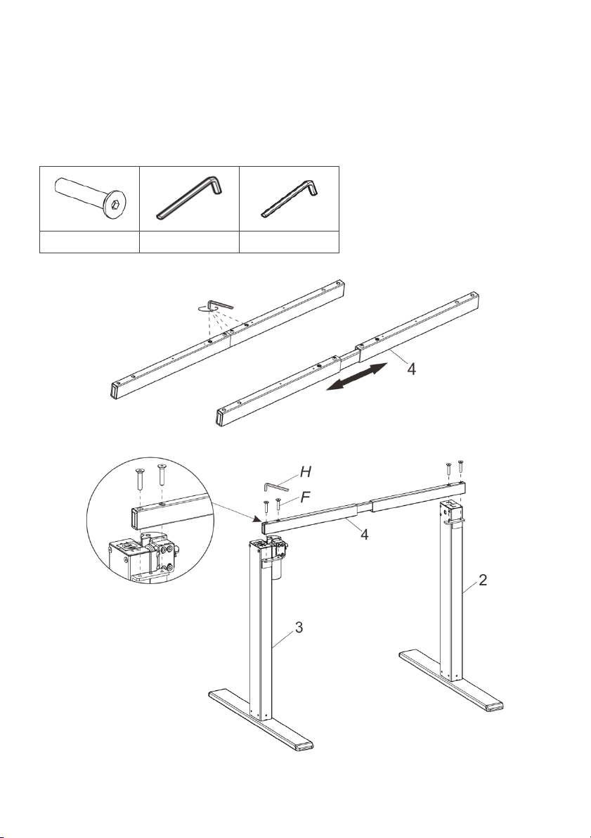
F M8 (x4)
5mm Allen key
4mm Allen key
Loosen
Adjust
Large holes
facing upwards
Step 2: Installing the supporting beam.
• Loosen screws on supporting beam (4) using the 4mm Allen key and adjust the
supporting beam to your desired width.
• Using the M8 screws (F) attach the supporting beam (4) to the lifting columns (2)(3)
and tighten using the 5mm Allen key.
Note: Ensure the large holes in the supporting beam (4) are facing upward.
Page 8
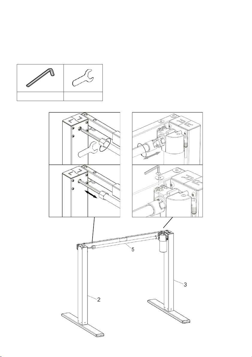
Step 3: Installing the transmission rod.
2.5mm Allen key
Spanner
Loosen
Insert
Rotate
Insert
Tighten
• Use the spanner to loosen the nut on the transmission rod (5).
• Insert the nut side of the transmission rod into the left lifting column (2).
• Attach the transmission rod (5) to the right lifting column (3) by rotating it clockwise
and use the 2.5mm Allen key to tighten screws on the transmission rod (5).
Note: Do not tighten the screws more than a 1/3 turn.
Page 9
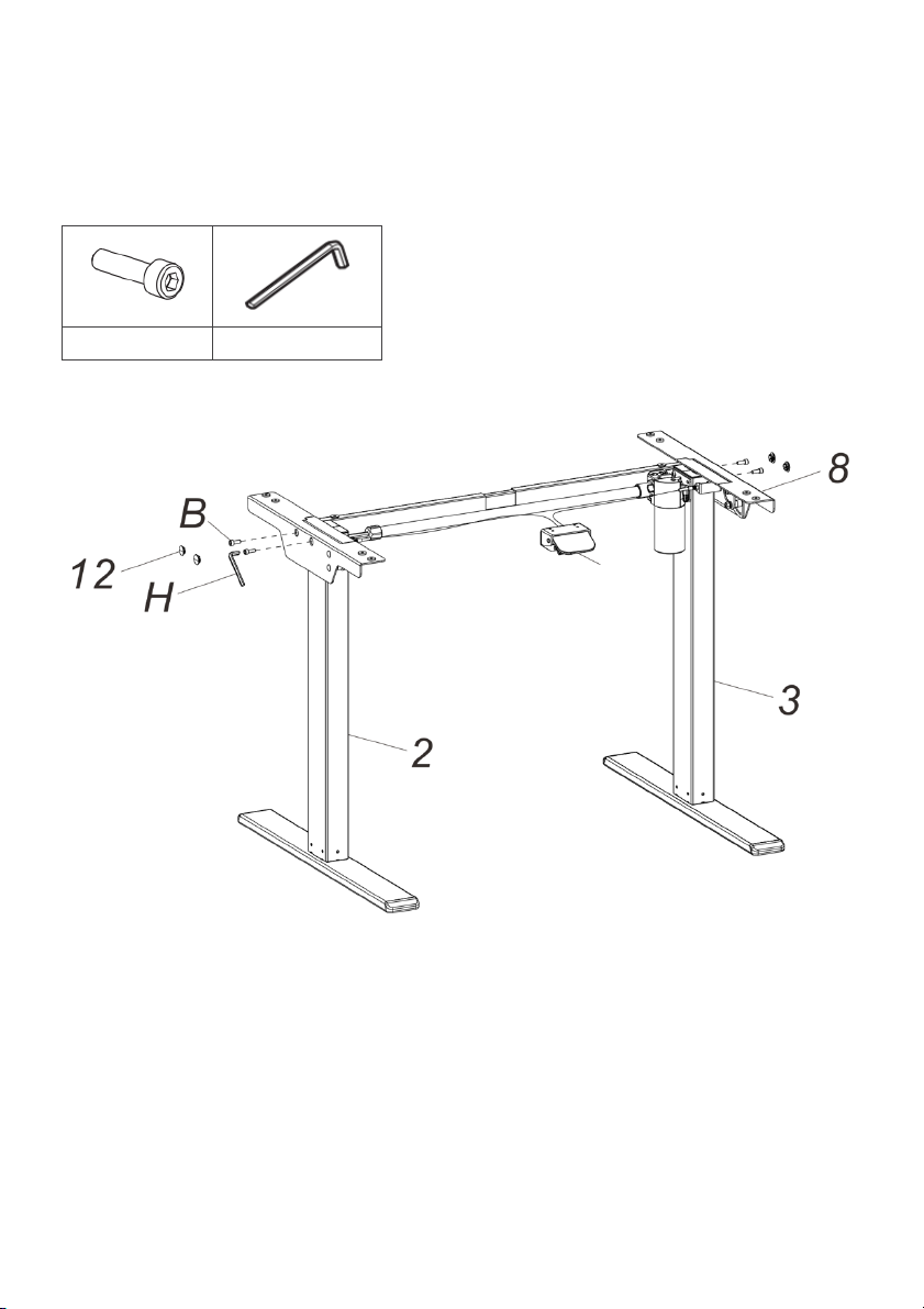
B (x4)
5mm Allen key
Handle
Step 4: Installing the side brackets.
• Using M6 screws (B) attach the side brackets (8) to the lifting columns (2)(3) and
tighten using the 5mm Allen key.
Note: Ensure the handle is installed on the same side as the motor.
• Insert the screw covers (12) into the side brackets (8).
Page 10
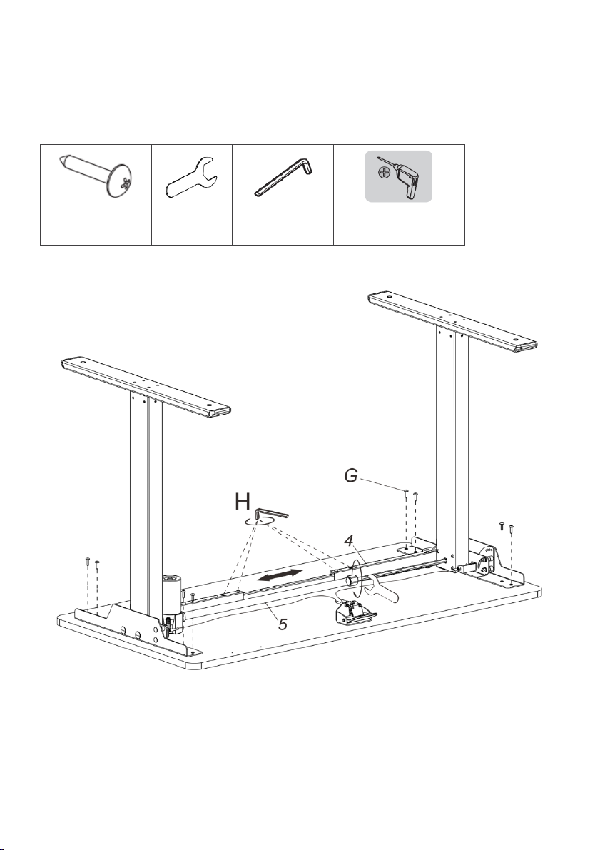
Step 5: Installing the desktop.
G Self-tapping
screws (x8)
Spanner
4mm Allen key
Drill or impact driver
• Adjust the support beam (4) and the transmission rod (5) to the appropriate length
according to the width of the desktop
• Attach the desktop with the self-tapping screws (G) using a drill or impact driver.
• Tighten the screws on the supporting beam and the nuts on the transmission rod using
4mm Allen key and spanner.
Page 11
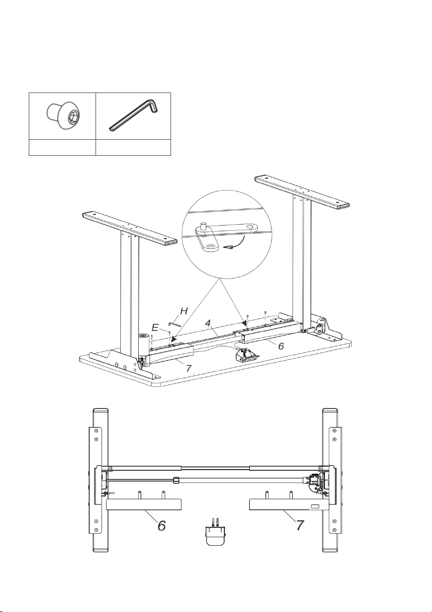
Step 6: Installing the baffles.
E M4 (x4)
2.5mm Allen key
• Tw i s t op e n the connecting plates on the left and right baffles (6)(7).
• Use the M4 screws (E) to attach the left and right baffles (6) (7) to the support beam
and tighten using the 2.5mm Allen key.
Note: Ensure the right baffle (7) is installed on same side at the motor.
Page 12
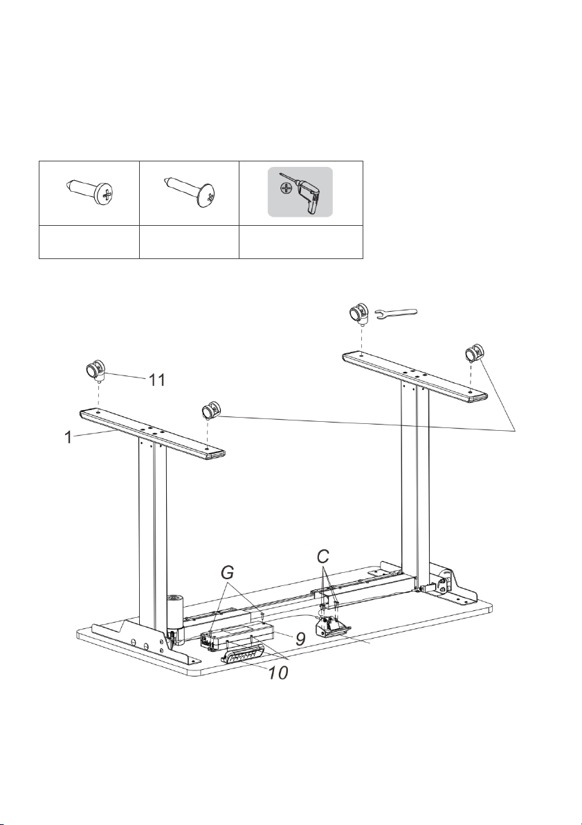
C Self-tapping
screws (x4)
G Self-tapping
screws (x8)
Drill or impact driver
Brakes
Handle
Step 7: Installing the control box, headset and castors.
• Attach the control box to the tabletop using the self-tapping screws (G).
• Attach the handle to the tabletop using the self-tapping screws (C).
• Attach the handset (10) to the desktop using the self-tapping screws (G).
• Attach the castors (11) to the feet (1) using a spanner.
Note: Ensure the castors with brakes are mounted on the same side as the handle.
Page 13
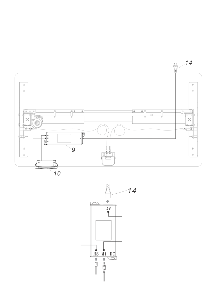
Handset
Power cord
Lifting column
Step 8: Connecting the control box.
• Fol low ing the dia gra m be low, conn ect the li ft ing col umn con nect or to th e co ntr ol box
(9).
• Connect the handset connector (10) to the control box (9).
• Connect the power cord (14) to the power adapter (8).
Page 14
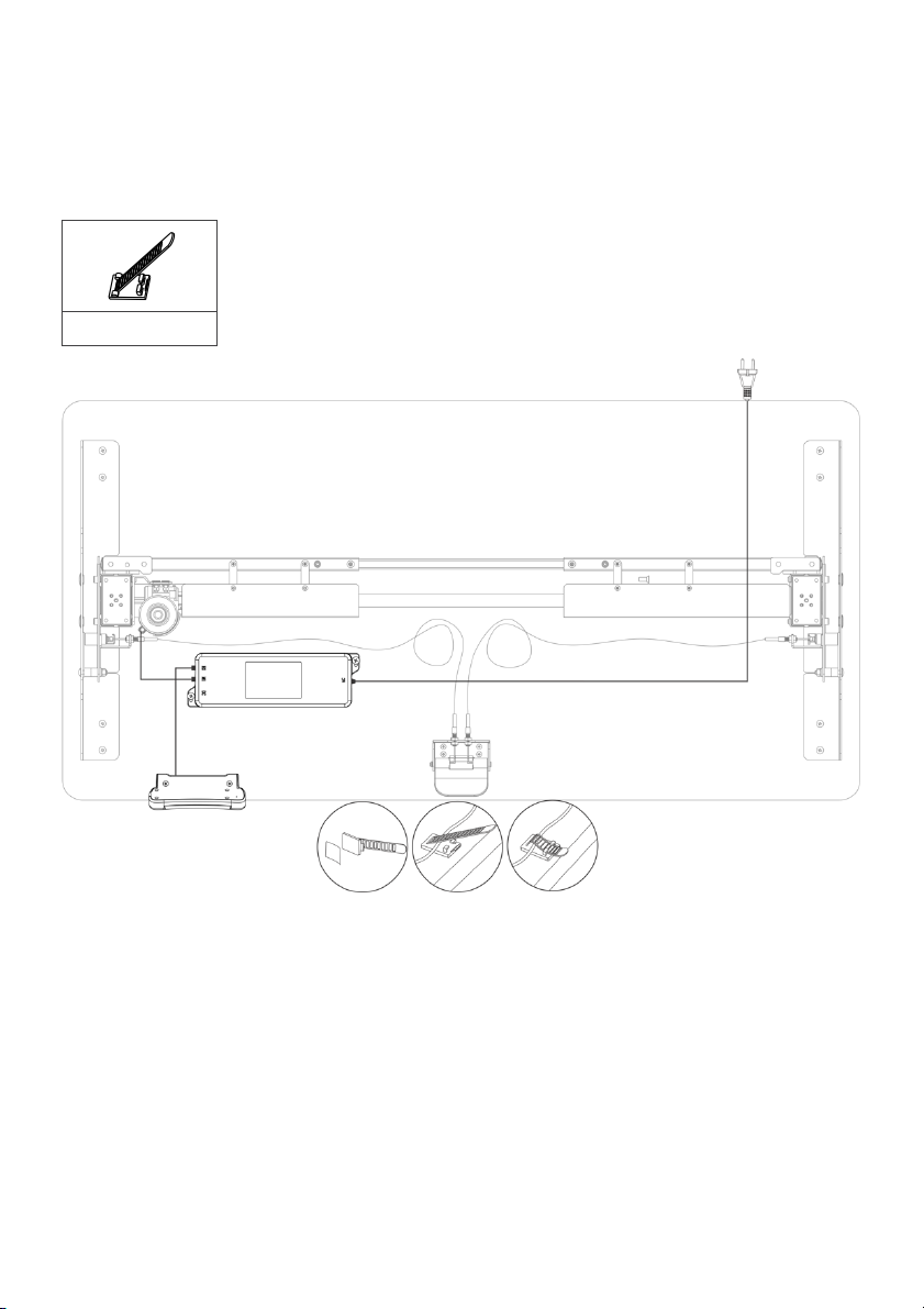
E Cable ties (x6)
Remove
backing
Attach
Secure
cables
Step 9: Cable management.
• Remove the adhesive backing and attach the supplied cable ties (E) to the underside
of the tabletop.
• Tidy up and secure all the cables in place using the cable ties (E).
Page 15
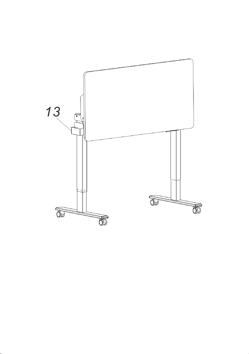
Step 10: Install the magnet storage box.
Attach the magnetic storage box (13) to the lifting column.
Note: The maximum weight capacity is 0.8kg.
Page 16
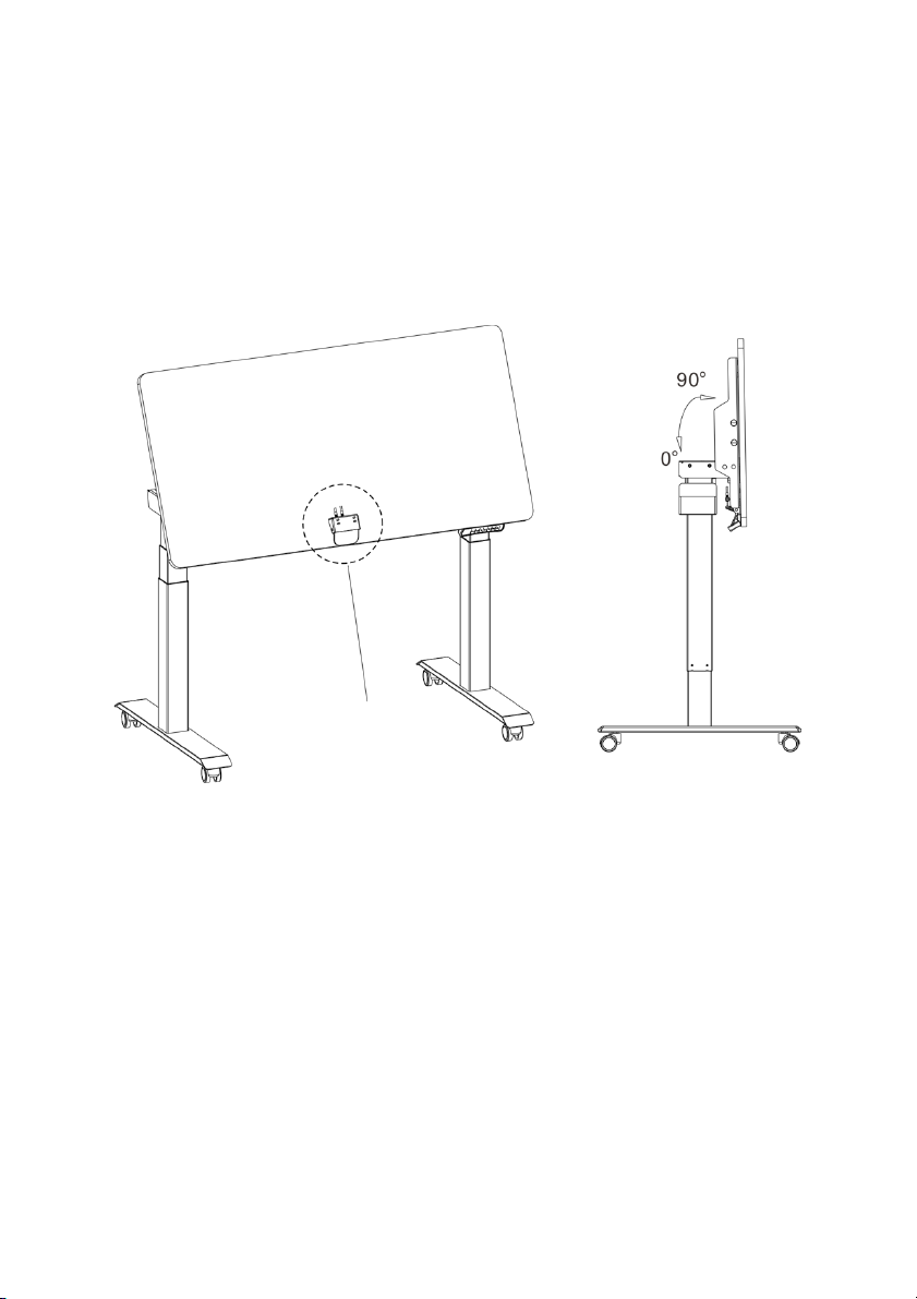
Handle
Step 11: Adjusting the angle of tabletop.
• The tabletop can be adjusted to five different angles (0˚, 60˚, 70˚, 80˚, 90˚).
• Press the handle and rotate the tabletop to the desired angle.
• Release the handle ensuring the tabletop locks into position with an audible ‘click’.
Note: Do not leave anything on the tabletop when adjusting the angle.
Page 17
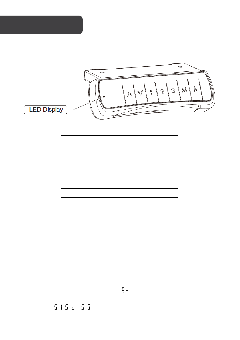
Button
Description
▲
Raise the desk height
▼
Lower the desk height
1
First user defined height position
2
Second user defined height position
3
Third user defined height position
M
Memory button
A
Alarm button
Handset Controls
Functions
Adjusting the height:
Press the ▲ or ▼ buttons to adjust the height of the desk. The LED display will show the
current height.
Memory function:
1. Once the desk has been set to the desired height, press the “Memory” button to
save the height. The LED will display .
2. Press “1”, “2” or “3” to save the height to the corresponding button. The LED will
display , or .
3. Pressing “1”, “2” or “3” will automatically adjust the desk to the height you saved.
Page 18
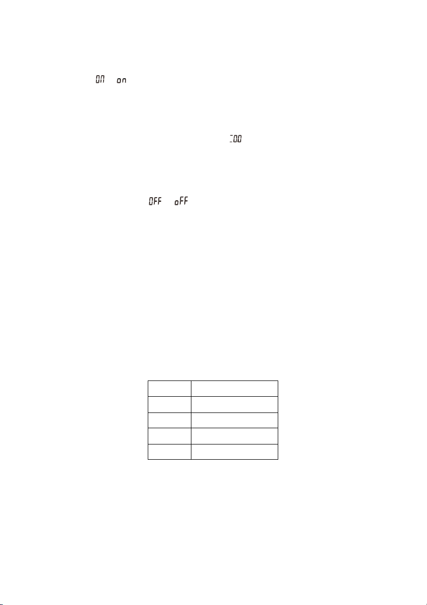
Setting
Sensitivity level
A-3
High
A-2
Medium
A-1
Low
A-0
Off
Stand up alarm:
1. Pressing the “Alarm” button will enable the stand up alarm function. The LED will
display or .
2. After 2 seconds the LED display will flash. By default the stand up alarm timer is
set to 45 minutes. Use the ▲ or ▼ buttons to adjust the timer to the desired length.
Press any of the other buttons or wait 5 seconds to save the timer.
3. During the countdown, any operation will reset the timer. When the countdown
reaches the set time the LED will display and a 10 second alarm tone will play.
Pressing any button within the 10 seconds will reset the stand up alarm timer. If no
buttons are pressed within the 10 seconds, a follow up alarm tone will play in 5
minutes. If no buttons are pressed during the follow up alarm, the stand up alarm
function will be deactivated.
4. To d e a c t i v ate the stand up alarm, press and hold the “Alarm” button for 3 seconds.
The LED will display or .
Anti-collision adjustment:
This desk features an anti-collision function. During height adjustment if the tabletop
comes in contact with an object it will stop and reverse to avoid damage.
1. By default, the anti-collision sensitivity is set to A-3 (high). Press and hold ▲ ▼
buttons simultaneously for 5 seconds to change the sensitivity levels of the anticollision function.
Note: If the LED does not display any codes after pressing the ▲ ▼ buttons, the
desk does not feature the anti-collision function.
2. Each time you press and hold the ▲ ▼ buttons the sensitivity level will cycle in the
following order: A-3, A-2, A-1, A-0. Refer to the table below for sensitivity levels.
Page 19

Column Stage
2
Max. weight capacity
70kg (horizontality)
Height range
760-1260mm
Width range
900-1350mm
Desktop angle range
0°, 60°, 70°, 80°, 90°
Storage box weight
0.8kg
Page 20
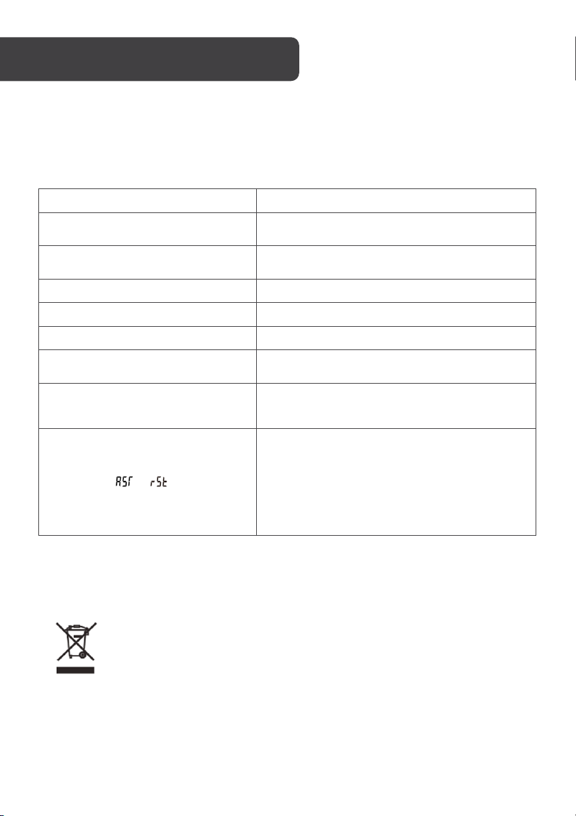
Problem
Solution
No response after pressing and
holding the down arrow.
Check if all the cables be connected well.
No response after pressing up or down
arrow.
Check if all the cables be connected well.
Rising speed is low.
Check if overloaded, max loading: 100kg.
Desk will go down but up.
Check the area for any obstructions.
The desk is sliding down on its own.
Check if overloaded, max loading: 100kg.
Controls are unresponsive after lots of
use.
Disconnect the power and wait for 18mins before
re-connecting the power.
Not enough up & down height.
Press and hold the "M" and "3" buttons together
until you hear two beeps. This will restore factory
settings.
LED displays or .
Press and hold the ▼ button. The desk will move
into the lowest position and then reverses until it
comes to a stop. When the LED displays the
height number, release the ▼ button.
If the desk doesn’t operate normally after the
reset, check all the cable connections and try
again in 18 minutes. If it still doesn’t operate
normally contact
help.Kogan.com
for support.
This marking indicates that this appliance should not be disposed with other
household wastes. To prevent possible harm to the environment or human
health from uncontrolled waste disposal, recycle it responsibly to promote
the sustainable reuse of material resources.
TROUBLESHOOTING
The following tips will help you detected and eliminate some common faults and errors. If
the problem cannot be fixed or the fault is not listed below, please contact help.Kogan.com
for support.
Disposal
Page 21
Page 22
Page 23
Page 24

Need more information?
We hope that this user guide has given you
the assistance needed for a simple set-up.
For th e mo st up-to-date guide for your product,
as well as any additional assistance you may require,
head online to help.kogan.com.
 Loading...