

Page 1
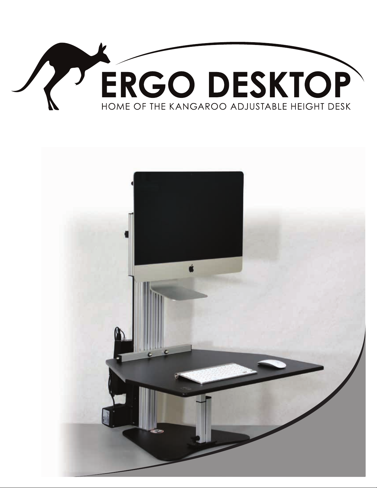
The elecTric MyMac Pro
Page 2

WARNING: FAILURE TO COMPLY WITH OR OBSERVE ALL ASSEMBLY, SAFETY AND OPERATION INSTRUCTIONS AND WARNINGS REGARDING THE
USE OF THIS PRODUCT MAY RESULT IN SERIOUS BODILY INJURY AND PROPERTY DAMAGE.
Prior to installment, use, and maintenance of the Ergo Desktop, any installer and any user of the Ergo Desktop must study this assembly and operation manual carefully, so as to gain a complete understanding of its contents. Assure that everyone who uses the Ergo Desktop is informed of the contents of this manual. This is the
responsibility of the Purchaser.
Please read the operation manual prior to the start of using the Ergo Desktop. It provides you with important information about safety, use, installation, and maintenance of the Ergo Desktop, and thus protecting you, your children, and avoiding damage on the Ergo Desktop and surrounding personal property.
Please guard this operation manual and pass it on to any future owner! Safe use of the Ergo Desktop is possible only when the operating instructions are read
completely and the instructions contained are strictly observed. Assure that this manual is located near the Ergo Desktop, and if possible, permanently axed to the
desktop.
Failure to comply with these warnings and the operation manual may result in serious damage to the system, one of the system’s components, serious bodily injury,
and/or damage to property. Persons who do not have the necessary experience or knowledge of the Ergo Desktop must not use the product.
Inappropriate use may cause damage to persons, property, and desktop.
CHILDREN SHOULD NOT USE THE ERGO DESKTOP!
Do not crawl, lie, or move around under the desktop frame. Do not sit, kneel, or stand on the desktop frame.
The electromotive, height-adjustable desktop and shelves are designed for workstations in dry work environments only. They have not been designed for other purposes than those included in this manual (i.e. they are not to be used in areas of high humidity or dampness, nor for lifting people). Any other use is at one’s own risk!
The desktop height is innitely adjustable up to 20.5 inches (52.07 cm), so that it can be set to the most ergonomically suitable working level.
Liability: The manufacturer accepts under no circumstances warranty claims or liability claims for damages arising from improper use or handling of the desktop other
than that described herein. The Ergo Desktop should be connected to a 120 VAC outlet. Place the Ergo Desktop in a safe distance from window frames, radiators,
furniture etc., so that people do not get stuck. The stabilization legs should be used when the Ergo Desktop work surface is not in the lowest position. Do not place
any objects or body parts underneath the desktop table, monitor shelves, rails, main horizontal work surface, and base of the Ergo Desktop (except for the stabilization
legs). Make sure no body parts, objects, or furnishings (i.e. cabinets, light xtures, bookcases, desk credenzas, desk hutches, etc.) are located above the Ergo Desktop
(which includes any laptops and/or monitors attached to the desktop). When using the Ergo Desktop, make sure no ngers, hands, or other body parts are placed near
the lifting tower or between any of the shelves or work surfaces.
Adults with reduced physical or mental abilities must not use the Ergo Desktop, unless they have been thoroughly instructed in the use of the apparatus and supervised
by a person who is responsible for the safety of these adults. Ergo Desktop is intended for use on level desks. If you determine that your desk is unlevel, you may wish
to improve the rmness of your desk prior to installing the Ergo Desktop. The base of the Ergo Desktop should be placed on a level surface measuring no less than
18” x 18” (60.96 cm x 60.96 cm). Only a keyboard and computer mouse should be placed on the Ergo Desktop work surface. Do not put pressure on the edge of the
work surface without the stabilization leg in place.
Extra Warnings: Do not use the Ergo Desktop if it has a damaged cord or plug. Do not pull or carry the Ergo Desktop by the cord, use cord as a handle, close a door
on the cord, or pull cord around sharp edges or corners. Keep cord away from heated surfaces. Do not unplug by pulling on cord. To unplug, grasp the plug; not the
cord. Do not handle the Ergo Desktop with wet hands. Keep all liquids away from the Ergo Desktop. Do not put any object or body part into openings. Keep hair,
loose clothing, ngers and all body parts way from openings and moving parts.
STAY ALERT. Do not use the Ergo Desktop when you are tired, distracted or under the inuence of drugs, alcohol or medication causing diminished control.
Before Installation, Re-installation, or Troubleshooting:
Stop the Ergo Desktop. Switch o the power supply and pull out the main power supply plug. Relieve the Ergo Desktop of any loads. If there is visible damage on the
product, it must not be installed.
Before Start-up:
Make sure Ergo Desktop has been installed as specied in this manual. System Connection - the individual parts must be connected before the control box is connected to the main power supply. If the control box makes unusual noises or has an odor, switch o the main power supply and contact us immediately. Make sure the
cables are not damaged. Make sure that no cables or cords can get jammed or stripped when raising or lowering the Ergo Desktop. Make sure all cables and wires
are not entangled with the Ergo Desktop and have enough length when the desktop is raised to the desired height. Be sure to measure the monitor stand and/or laptop
before placing it on the monitor shelf, to insure that the monitor shelf is large enough to hold the monitor stand and/or laptop. When the Ergo Desktop has been assembled (see assembly instructions in the attached manual) the feet should be installed so that the desktop is level and does not shift.
Maintenance:
Stop the Ergo Desktop. Switch o the power supply and pull out the main power supply plug. Clean dust and dirt on the outside of Ergo Desk and other components
at regular intervals. Inspect the connections, cables, and plugs and check for correct functioning as well as the security of the connection points. The cleaners and
disinfectants must not be highly alkaline or acidic.
1 YEAR LIMITED WARRANTY
This warranty covers any defects in materials and workmanship of the enclosed product. Ergo Desktop LLC will repair or replace any defective materials due to craftsmanship of the product. This warranty does not cover any problem or injury caused by misuse, abuse, accidents, or acts of God, such as oods or hurricanes. Also
consequential and incidental damages are not covered under this warranty. Coverage terminates if you sell or otherwise transfer ownership of the product. If you feel
you have a defective product, please call 1-866-232-7988 or email [email protected] for instructions prior to returning this item. A Return Authorization Number
is required before sending back. Please ship all returns to:
Ergo Desktop LLC
457 Grand Lake Road
Celina, OH 45822
We will inspect the product and contact you within a timely manner to give you the results of our inspection. We reserve the right to repair or replace the product at our
discretion. However, we may replace the product with the same or greater features. This limited warranty gives you specic legal rights, and you may also have other
rights which vary from state to state.
Page 3
The elecTric MyMac Pro - Assembly Instructions
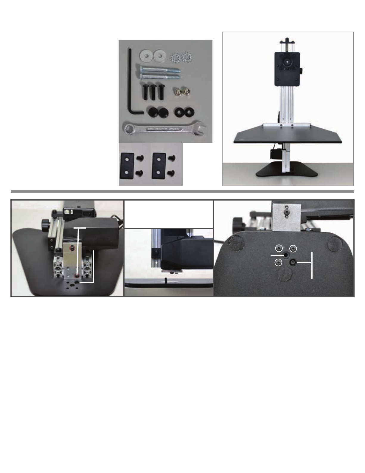
Assembly Parts list
A. (6) Black Screw Covers
B. (2) 1/4-20 x 3.50 Hex Head Bolts
C. (1) 5/32 Allen Wrench
D. (2) Fender Washers
E. (2) Acorn Nuts
F. (3) 1/4-20 x 7/8 BHCS (THESE 3
ARE ALREADY THREADED IN
THE LIFT ASSEMBLY)
G. (2) Thick Black Washers
H. (1) 7/16 Wrench
I. (2) Locking Star Washers
J. (2)1 x 2 plastic cap
K. (4) 1/4-20 x 3/8 BHCS
C
D
B
F
(3)
H
J
J
K
(3)
I
E
A
K
G
bottom of lifting assembly
oversized hole
matched
up with already
installed
button head
lifting
assembly
single
button
head
oversized
hole to
match with
button
head
screw
top of steel base plate
image shows back side of
lifting assembly lining up the button
head bolts
three button heads that need
screwed in and tightened
not used
bottom of base plate
Step 1, 2 Step 3 Step 4
Steps 1-4 attaching the steel base plate to the lifting assembly
Step 1: Lay the lifting assembly on a solid surface with the back side up as shown. Notice the single Button Head
Bolt in the assembly union plate. DO NOT LOOSEN THE SINGLE BUTTON HEAD BOLT THAT IS NOTATED.
LOOSEN THE 3 OTHER BOLTS TO ADD THE LIFTING ASSEMBLY TO THE BASE PLATE.
Step 2: Notice the (2) oversized holes in the Base Plate. The Single Button Head Bolt will go into the oversized hole
on the top right, while the other 3 holes should line up with the base. The center oversized hole is not used with this
unit.
Step 3: With the Base Plate over hanging the table about 2 inches, hold the Lifting Assembly above the Base Plate
and align the Single Button Bolt into the oversized hole. Place one 1/4-20 x 7/8 BHCS{F} through the base plate to
screw in the lifting assembly.
Step 4: Insert and thread the other (2) 1/4-20 x 7/8 BHCS{F} through the Base Plate and into the Lifting Assembly.
Once all (3) bolts are threaded in, tighten securely with the 5/32 allen wrench{C}. Lifting Assembly should be at
against the Base and all three bolts should look like the picture above.
Page 4
The elecTric MyMac Pro - Assembly Instructions
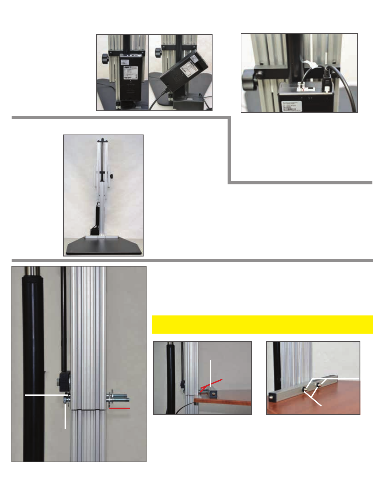
Step 5: Connecting
the power for the lifting
assembly. Go to the back
side of the lifting assembly and turn the power
box to the left. Push the
plug securely into the
power box.
Raise the lifting assembly to attach the work surface
Once you have
connected
your cables,
plug the unit
into an outlet and press
the up arrow
on the work
surface to raise
the unit 3/4 all
the way up like
the picture to
the right
STEP 7,8,9
Note: If your work
surface does not
move. First check your
connections, then
hold the down arrow
on the controller for 6
seconds while
plugged in to be
reinitialized.
Step 7: Put (1) Locking Star Washer{I} on each of the 1/4 –20 x 3.50
Hex Head Bolts{B}.
Step 8: Insert the (2) 1/4-20 x 3.50 Hex Head Bolts{B} through the
holes in the Vertical Rail.
Step 6: Connecting the controller from
the work surface and cable to the actuator.
Connect the cable from the work surface
that holds the controller into port “A1“.
Connect the cable from the actuator into
the right port labeled “1“ as
shown above.
We suggest keeping the lifting assembly
raised up, to step 11. Once step 11 is
completed the unit can be lowered to the
complete sitting position.
Locking Star
Washer
1/4-20 x 3.50
Hex Head Bolt
Fender
Washer
Step 9: Put (1) Fender Washer{D} on each of the 1/4-20 x 3.50
Hex Head Bolts{B} on the other side of the Vertical Rail.
STEP 10
horizontal
rail
Fender
Washers
Work
Surface
Step 10: Lift the Work Surface up and align the holes
in the Horizontal Rail with the
(2) 1/4-20 x 3.50 Hex Head
Bolts{B}. Push the Work Surface
onto the Hex Head Bolts until
Step 11: Put (1) Black Washer{G} and (1) Acorn Nut{E} on
the end of each of the Hex
Head Bolts. Using the 7/16
wrench{H} tighten the Acorn
Nuts securely.
STEP 11
Acorn Nuts
Black Washers
the threads of the bolts come
through the Horizontal Rail.
Page 5
The elecTric MyMac Pro - Assembly Instructions
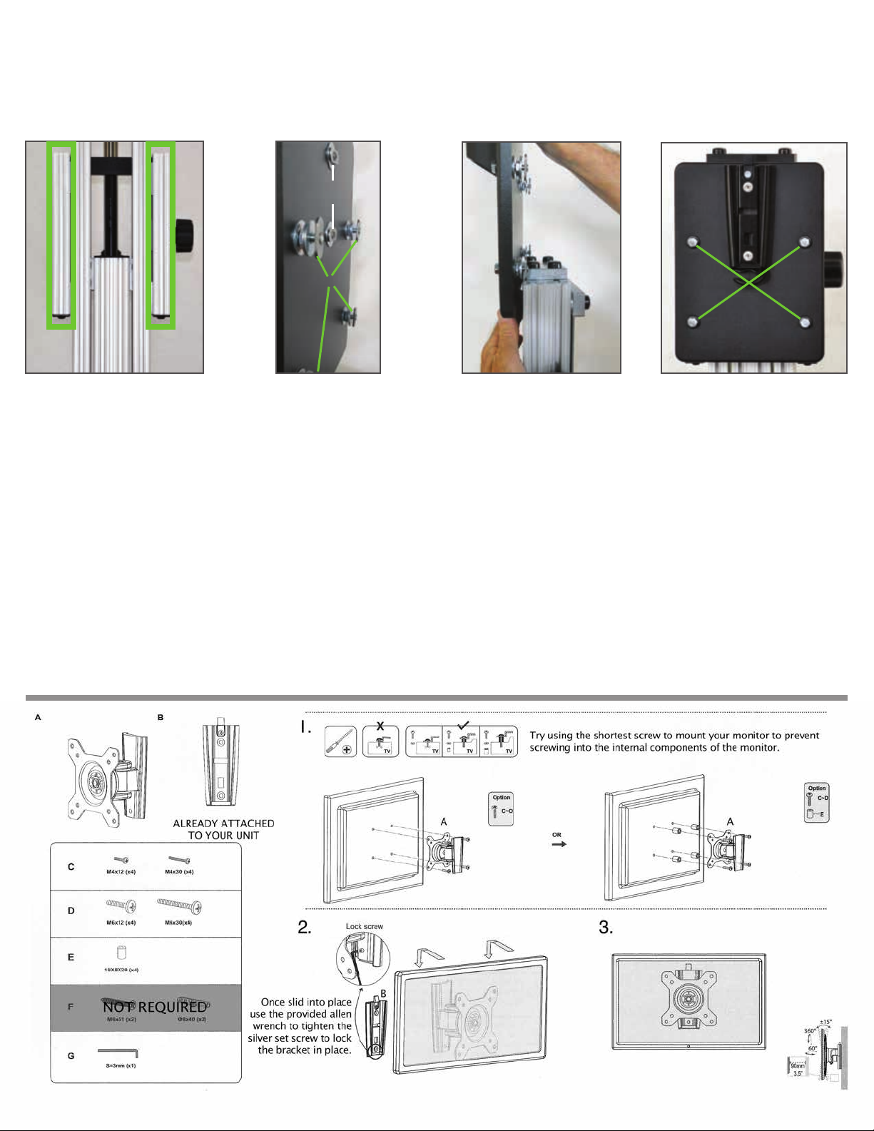
Steps 12-16 Attaching the monitor backer board
STEP 12
Step 12: Identify the
monitor vertical rails you
will be using to slide on
the backer board. You
will notice that the top of
those rails are exposed.
Step 16: Add the 1x2” rectangular plastic caps {J} to the tops
of the exposed rail from step 12. Use 2 3/8” button head
screws{K} to attach the caps to the vertical monitor rails.
Tighten with the provided 5/32 allen wrench{C}.
STEP 13 STEP 14 STEP 15
do not
adjust
e-nuts
Step 13: Prep
the backer
board by loosening the 4
e-nuts shown
in the image
above.
Step 14: Utilizing the
monitor vertical rails
from step 12, slide the
backer board into the
rails with the e-nuts on
the back side.
tighten
and cap
Step 15: After the backer
board is positioned, hand
tighten each of the hex
head bolts notated above
with the provided 7/16
wrench{H}. After the bolts
are tight, press on the
round plastic caps{A} to
conceal the bolts.
Follow the instructions below to mount your monitor. Depending on the mac product you have will also depend what
apple mounting adaptor solution you will require. Step 1 below you will be screwing the mount to the apple adaptor.
Page 6
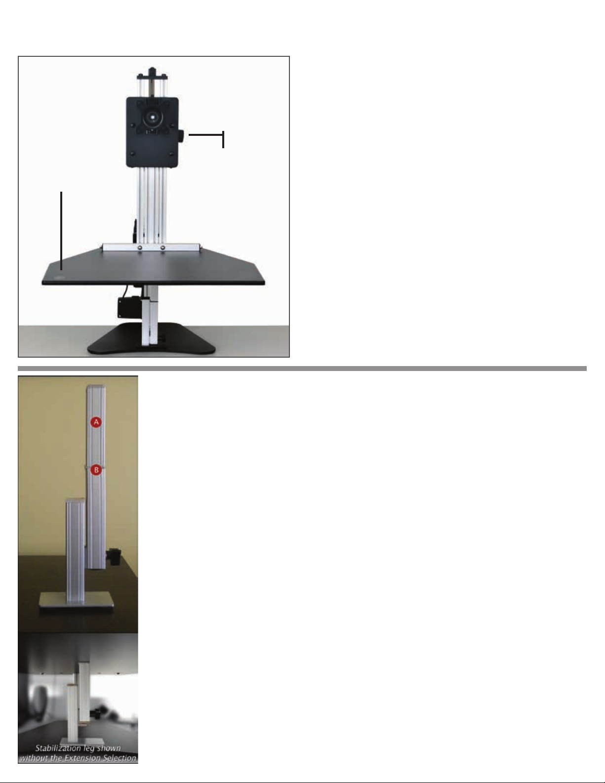
The elecTric MyMac Pro - IN USE INSTRUCTIONS
The Electric MyMac Kangaroo Pro is designed to hold (1)
monitor on a VESA 75 x 75 or 100 x 100mm compatible
bracket and your keyboard and mouse on the main work
surface. The Electric MyMac Kangaroo Pro has a spring that
assists in raising your monitor and works best when your
monitor is in place. This reduces the amount of pressure
A. monitor
brake
B. control
button
needed to raise and lower the monitor.
The main work surface is powered by an electric motor and
can lift up to 150lbs. When raising and lowering the unit,
please be aware of your surroundings and cable lengths.
When lowering be sure to remove the leg and make sure no
objects are obstructing the down travel.
Raise and lower the monitor by loosening the monitor
brake(A) and either lift up or push down on the monitor
and/or backer board. Once the monitors reach you desired
level, tighten the monitor brake.
Raise and lower the main work surface by pressing the up
or down arrow on the control button(B).
The STabilizaTion leg
Your adjustable height desk top unit comes with an adjustable leg that can be used to
give you maximum stability when you are using “The Kangaroo” in the standing position.
Raise the Kangaroo work surface to your desired standing height and tighten the work
surface brake.
Place the adjustable leg under the work surface and loosen the adjustable leg brake. Only
loosen the brake by a turn or two, too much and the brake will disengage from the slot.
Extend the adjustable leg until it engages the bottom of the work surface and then tighten
the adjustable leg brake.
The leg is shipped with the extension section installed to give you additional height adjustment. If this is too tall for your application, simply unscrew the extension selection.
If you have the taller version of the leg there is no top extension selection.
A. Extension selection
B. Extension selection screws into this location
AlwAys remove the stAbilizAtion leg before
lowering
the unit
 Loading...