

Page 1
The MyMac Kangaroo Pro - aSSeMBLy InSTrUcTIonS
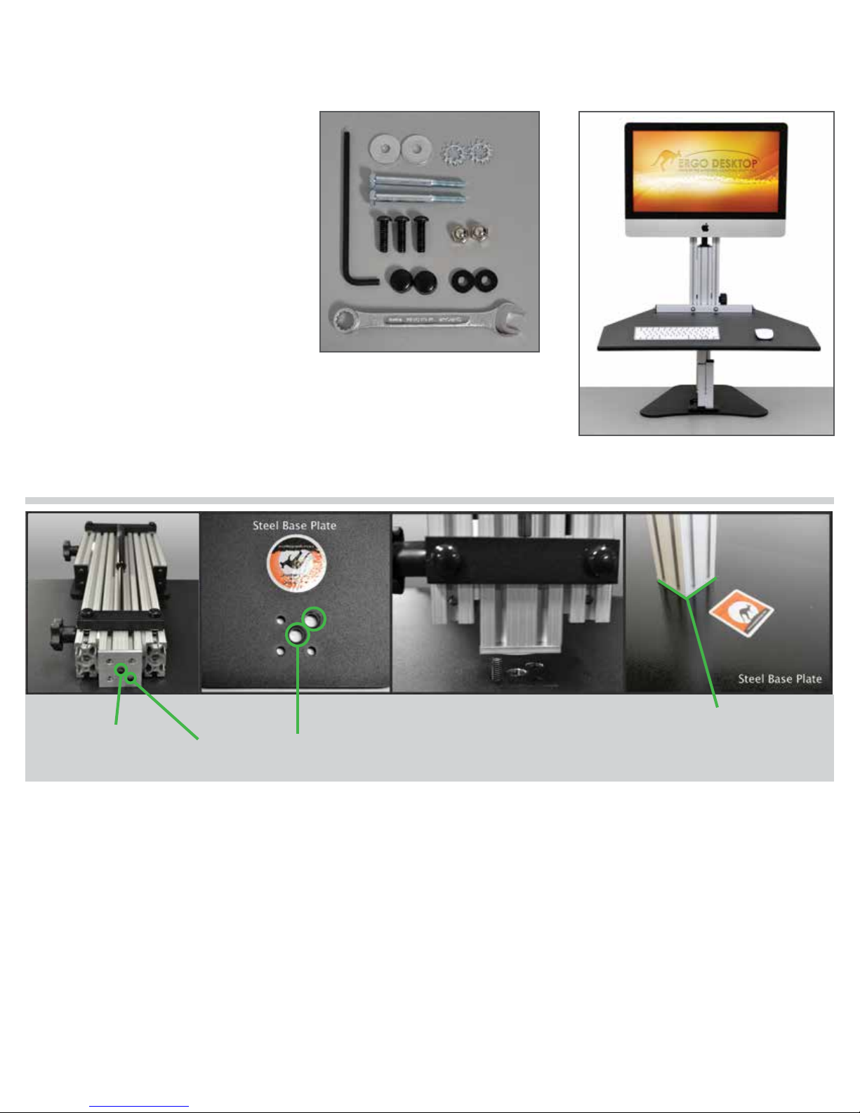
Assembly Parts list
A. (2) Black Screw Covers
C
D
I
B. (2) 1/4-20 x 3.50 Hex Head Bolts
C. (1) 5/32 Allen Wrench
B
D. (2) Fender Washers
E. (2) Acorn Nuts
F. (3) 1/4-20 x 7/8 BHCS
F
E
G. (2) Thick Black Washers
H. (1) 7/16 Wrench
I. (2) Locking Star Washers
A
H
G
Apple mounting plate and mount
instructions included. Please visit this
youtube link below to view an instructional
video on attaching your apple display to the apple adaptor kit.
www.youtube.com/watch?v=4D5_uMBMaCY
The Apple adaptor kit provides the 100 x100mm hole pattern needed
to attach to the mount on the unit.
Back Side of
Lifting Assmebly
Step 1 Step 2 Step 3 Step 4
Threads of Spring
Single button
head screw
Oversized Holes
Lifting assembly
should be at against
the base plate
when tight
Step 1: Lay the lifting assembly on a solid surface with the back side up as shown. Notice the single Button Head
Bolt in the assembly union plate. DO NOT LOOSEN THE SINGLE BUTTON HEAD BOLT THAT IS NOTATED.
Step 2: Notice the (2) oversized holes in the Base Plate. The Single Button Head Bolt will go into the oversized hole
on the top right, while the other 3 holes should line up with the base. The center oversized hole is not used with this
unit.
Step 3: With the Base Plate over hanging the table about 2 inches, hold the Lifting Assembly above the Base Plate
and align the Single Button Bolt into the oversized hole. Place one 1/4-20 x 7/8 BHCS{F} through the base plate to
screw in the lifting assembly.
Step 4: Insert and thread the other (2) 1/4-20 x 7/8 BHCS{F} through the Base Plate and into the Lifting Assembly.
Once all (3) bolts are threaded in, tighten securely with the 5/32 allen wrench{C}. Lifting Assembly should be at
against the Base and all three bolts should look like the picture above.
Page 2
The MyMac Kangaroo Pro - aSSeMBLy InSTrUcTIonS
Locking Star
Locking Star
Washer
Washer
1/4-20 x 3.50
1/4-20 x 3.50
Hex Head Bolt
Hex Head Bolt
STEP
5,6,7
Fender
Washer
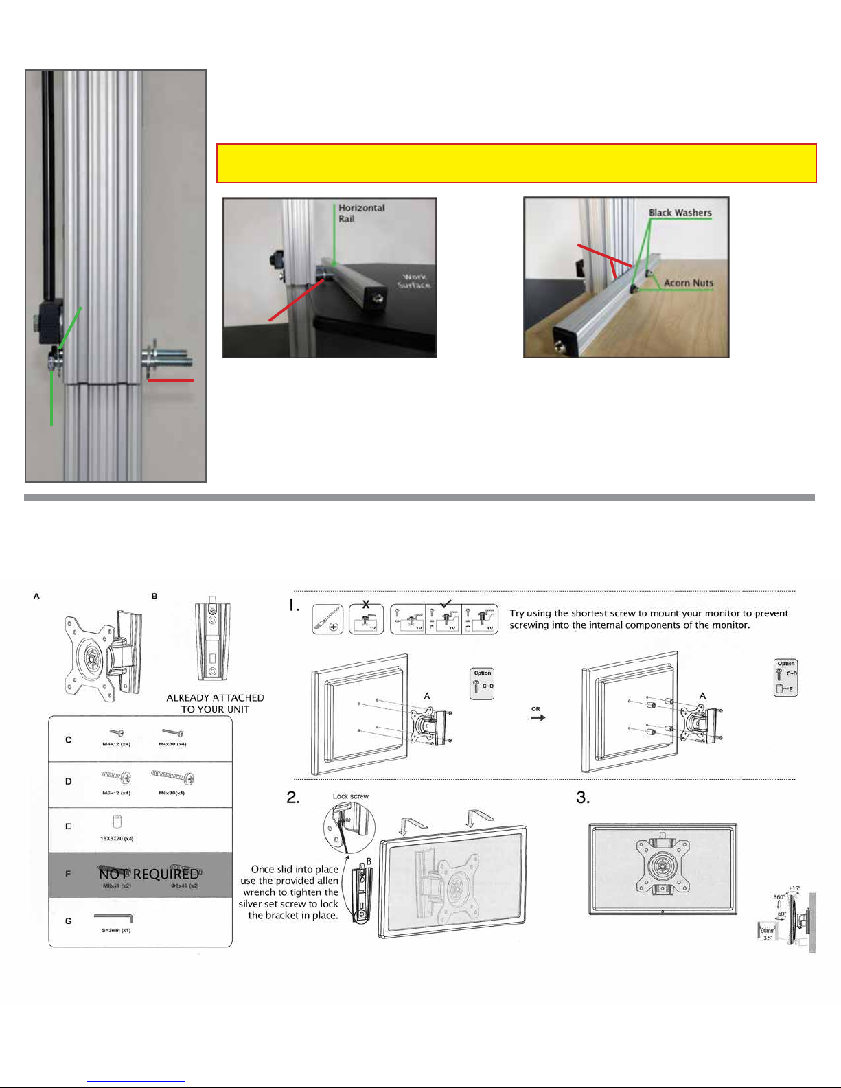
Step 5: Put (1) Locking Star Washer{I} on each of the 1/4 –20 x 3.50 Hex Head Bolts{B}.
Step 6: Insert the (2) 1/4-20 x 3.50 Hex Head Bolts{B} through the holes in the Vertical Rail.
Step 7: Put (1) Fender Washer{D} on each of the 1/4-20 x 3.50 Hex Head
Bolts{B} on the other side of the Vertical Rail.
STEP 8 STEP 9
Hidden
Fender
Washers
Fender
Washer
Step 8: Lift the Work Surface up and
align the holes in the Horizontal Rail with
the (2) 1/4-20 x 3.50 Hex Head Bolts{B}.
Push the Work Surface onto the Hex
Head Bolts until the threads of the bolts
come through the Horizontal Rail.
Step 9: Put (1) Black Washer{G} and (1)
Acorn Nut{E} on the end of each of the
Hex Head Bolts. Using the 7/16 wrench{H}
tighten the Acorn Nuts securely.
Step 10: Mount your monitor using the provided apple adaptor. The apple adaptor instructions will be provided
separately. Follow the mounting instructions below to mount your monitor to the adaptor.
Page 3
The MyMac Kangaroo Pro
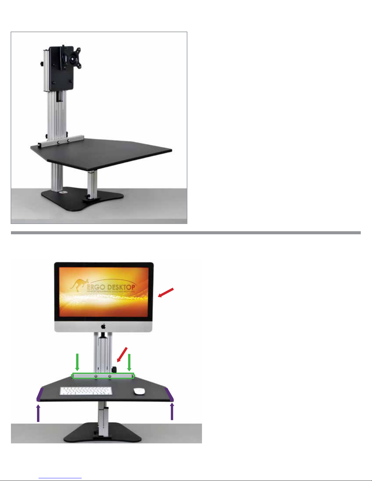
The MyMac Pro is designed to hold (1) iMac 24” or
27”, Cinema Display, or Thunderbolt on the VESA
compatible bracket and your keyboard and mouse
on the work surface.
Your MyMac Pro is shipped in the down position
with the Main Brake tightened. The MyMac Pro has
(2) very strong springs that assist in raising your unit
to the standing position. It is best to keep the unit
in the down position until you have your iMac or
Mac monitor mounted to the unit. This reduces the
amount of pressure needed to lower the unit.
Always push down with both hands on the horizontal
rear rail when lowering the work surface.
how To USe The MyMac Kangaroo Pro
A. Monitor Brake
(Hidden behind
monitor)
C. Main Brake
B. Push down hereB. Push down here
D. Lift Here
D. Lift Here
Your iMac is very heavy and the springs used to
support the weight are very strong. It may take
a few days to get used to the body mechanics
required to lower the unit.
To raise the MyMac Kangaroo Pro, loosen the
main brake(C) and lift the main work surface on
the sides(D & D).
To raise your monitor/iMac, loosen the
monitor brake(A) and lift the monitor to the
desired height.
To lower the MyMac Kangaroo Pro, loosen the
main brake(C) and lean into the unit using your
upper body weight pushing down with both hands
on the horizontal bar at the rear of the main
horizontal work surface (B & B).
To Lower the monitor, loosen the
monitor brake(A) and push down with one or two
hands on the monitor.
VESA compatible Bracket
Instructions Included
A. Monitor Brake
B. Work Surface Rail
C. Main Brake
D. Main Work Surface
Page 4
adjUST The SToPPIng BoLT
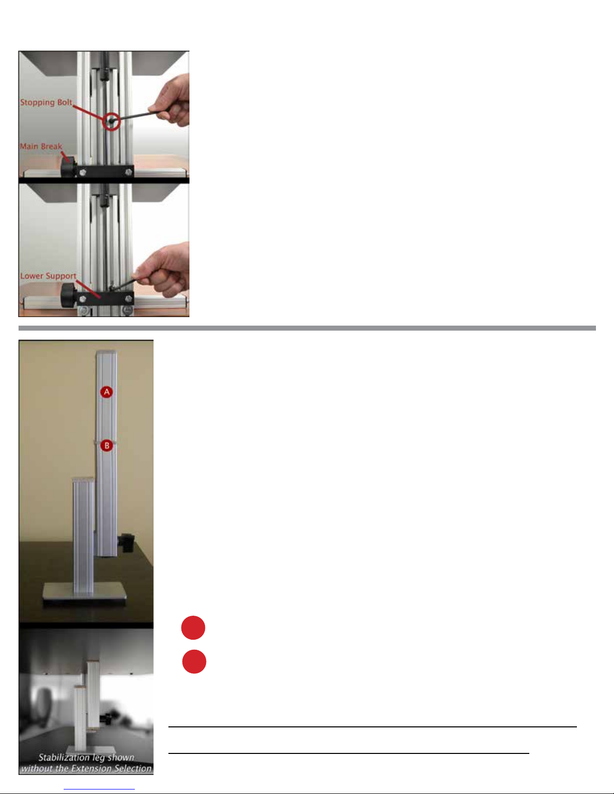
On the back side of your unit you will notice a small bolt located on the
lifting tower. This bolt is used as our work surface stopper. It is currently set
at 15”, the highest our unit should go. This setting is for a 6’2“ user on a 30”
high desk. If you are shorter than this, raise the unit to your desired height
and tighten the Main Brake. Adjust the stopping bolt by loosening the bolt
with one turn and drop the bolt down to reach the lower support, and
re-tighten the stopping bolt.
If you are a taller individual and need to raise the stopping bolt, please note
that the work surface can get up to 16 1/2 inches but you will be raising the
unit into the oil dampening zone of the spring. This makes it a little more
difcult to lower the unit into the seated position when raised to this
maximum point.
Our work surface should only be raised to your belt or navel line. This creates
a 90-110 degree angle in your elbows which is suggested in the standing position. This will also allow you to lower the unit with ease by simply
transferring your upper body weight into the back of the unit.
The STaBILIzaTIon Leg
Your adjustable height desk top unit comes with an adjustable leg that can be used
to give you maximum stability when you are using “The Kangaroo” in the standing
position.
Raise the Kangaroo work surface to your desired standing height and tighten the work
surface brake.
Place the adjustable leg under the work surface and loosen the adjustable leg brake.
Only loosen the brake by a turn or two, too much and the brake will disengage from
the slot.
Extend the adjustable leg until it engages the bottom of the work surface and then
tighten the adjustable leg brake.
The leg is shipped with the extension section installed to give you additional height
adjustment. If this is too tall for your application, simply unscrew the extension
selection.
A Extension selection
B Screws into here
always remember to remove the stabilization
leg before lowering your work surface
 Loading...