

Page 1

EMCTM-MS2
Flat Panel Display Mount
Page 2

Congratulations on purchasing the EMCTM-MS2. This
is shipped with all proper installation hardware and
components. Please verify that none of these parts are
missing and/or damaged before assembly. If any parts
are missing/damaged please stop assembly and contact
ErgoMounts 01252 333326
Parts List
Installation Tools
Phillips Head Screwdriver
Pencil
Level
Soft Material/Blanket
Tape Measure
Thread Depth Indicator
1/2" Socket and Wrench
Drill Gun
1
EMCTM-MS2 Wall Plate (Qty 1)
Mounting Brackets (Qty 2)
5/16” Flat Washers (Qty 6)
M10 x 12mm Hex
Head Screws (Qty 4)
Griplate ™ (Qty 6)
M6 x 30mm Lateral Shift
Locking Screws (Qty 2)
M6 x 12mm Safety Knobs
(Qty 2)
Universal Spacer
(Qty 24)
2
3
4
5
6
7
8
M4 x 30 (Qty 6)
M4 x 25 (Qty 6)
M4 x 16 (Qty 6)
M5 x 30 (Qty 6)
M5 x 25 (Qty 6)
M5 x 16 (Qty 6)
M6 x 45 (Qty 6)
M6 x 30 (Qty 6)
M6 x 25 (Qty 6)
M6 x 16 (Qty 6)
M8 x 70 (Qty 4)
M8 x 45 (Qty 6)
M8 x 30 (Qty 6)
M8 x 25 (Qty 6)
M8 x 16 (Qty 6)
Page 3

Installation
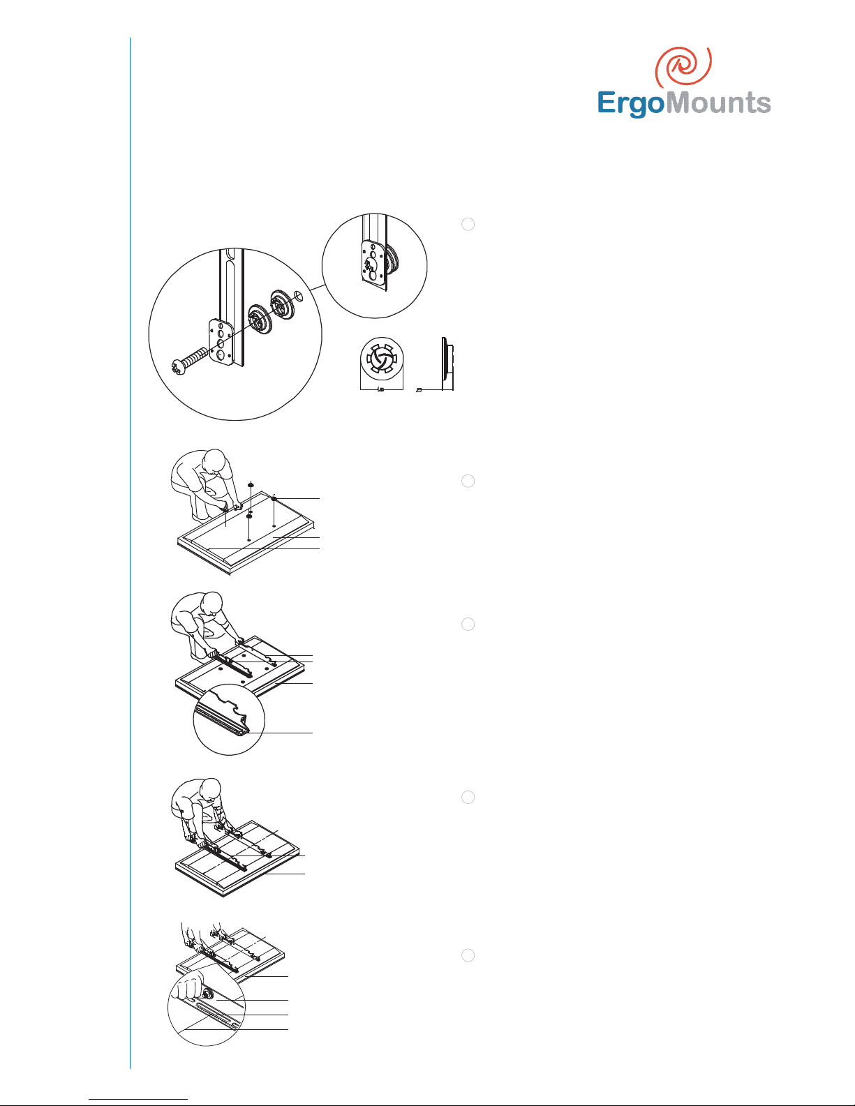
Insert the thread depth indicator (supplied) through
the thread inserts found on the back of the at
panel to make sure the inserts measure the same full
depth and mark it.
Locate the correct diameter screw for the thread
insert. Compare your marking to the screws
supplied.
If the selected screw is longer than the marking on
the thread depth indicator, DO NOT USE this screw.
The screw length must not bypass the marking.
Select another screw size ( gure 2 and 3), unitl you
nd one that comes closest to your mark without
going past.
1
2
3
Thread Depth Indicator
1
2
3
4
Inverted fl at
panel display
Marking the depth
Thread insert
Thread depth indicator
Thread depth
indicator
Screw
Marking
Screw Thread depth
indicator
Marking
NB Proper installation procedure by quali ed
personnel as outlined in the installation instructions
must be adhered to. Failure to do so could result in
serious personal injury and possible damage to the
at panel.
NB Invert the at panel, place it on a soft, at surface
to prevent damage to the at panel. Use a blanket,
foam, etc. Failure to do so will result in damaging
the at panel. Do not lay the at panel on the oor
without any protection to the glass. The at panel
is heavy and fragile. At least (2) quali ed personnel
are strongly recommended for installation of this
product. Failure to do so could result in serious
injury and possible damage to the at panel.
Once the at panel is inverted, use a measuring tape
to nd the centre of your at panel measuring from
outside to outside of the chasis.
Use a pencil to lightly mark the centre of your at
panel.
Finding the centre of the Plasma display
C
L
Top of Flat Panel
Tape Measure
Inverted Flat Panel
Bottom of Flat Panel
L
C
1
2
Marking the Centre of the
Flat Panel
Inverted Flat Panel
Page 4
Installation
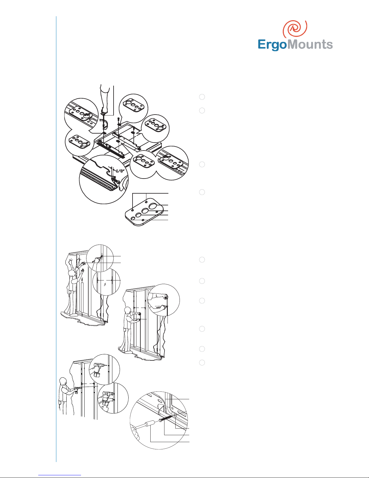
The Universal Spacer may be stacked ve (5) high,
for a total stacking height of 1 -1/4". The universal
spacers must be stacked in the direction shown
above. The universal spacers must be placed
between the mounting bracket and the at-panel.
The universal spacer can t M4, M5, M6 and M8
screws sizes.
Place the universal spacers over the mounting
points on the at panel
Lay the mounting brackets (stamped arrows facing
out) on the display, over the mounting points.
Match the centre of viewing guide with the centre
line you marked in step 1.
The mounting brackets are designed with a centre
viewing guide on the side.
1
Positioning the Mounting Brackets
1
Universal Spacers Installation
2
3
NB If your display has uneven mounting points, or
recessed mounting points, please use the provided
universal spacers.
Universal Spacers
Inverted Flat Panel
Centre Mark
L
C
4
Left Mounting Bracket
Right Mounting Bracket
Bottom of Flat Panel
Arrows Facing Out
Align the Mounting Brackets
Inverted Flat Panel
Bottom of Flat Panel
Mounting Bracket
Centre of Viewing Guide
Centre Line
Page 5
Installation
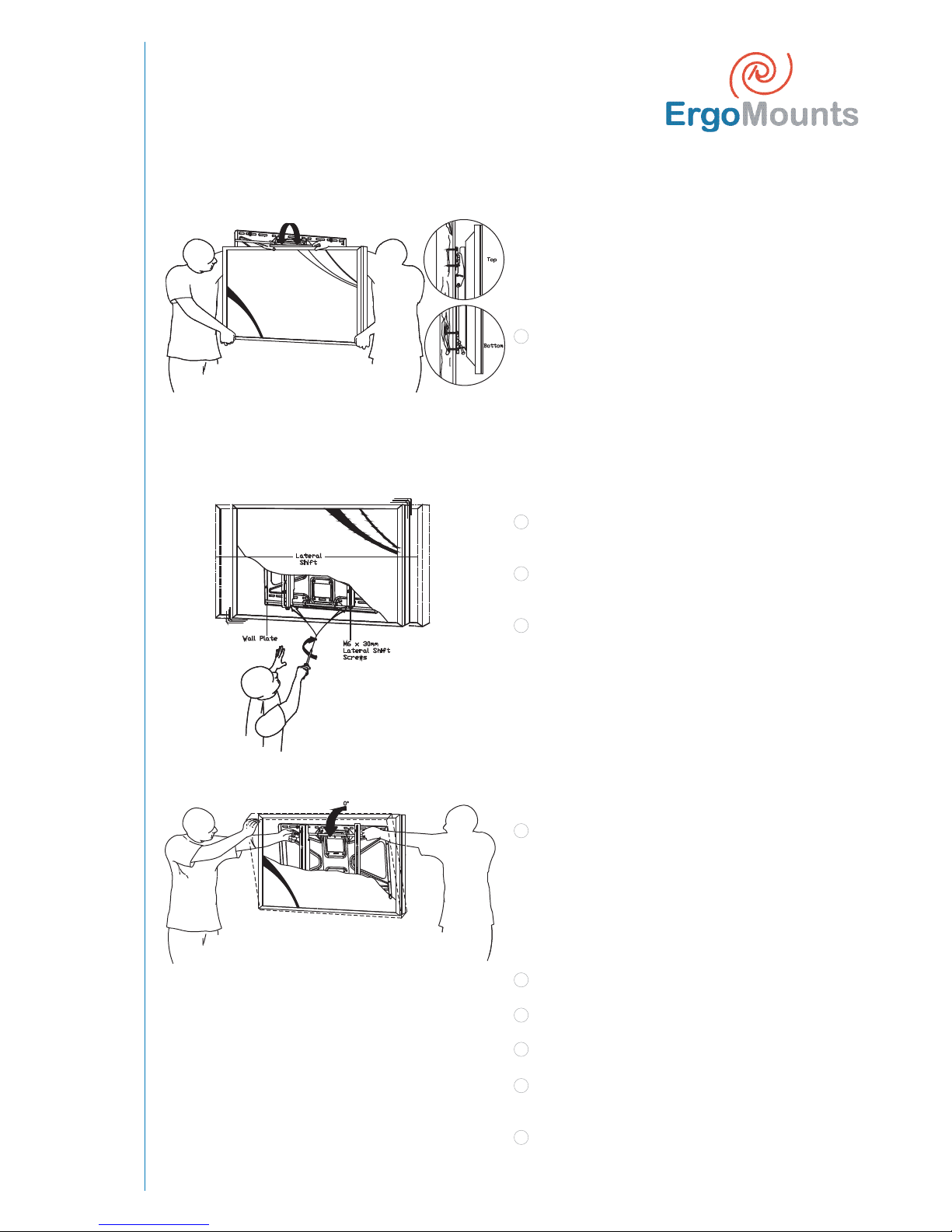
The Griplate™ has M4, M5, M6 and M8 hole patterns
to t the hardware that your at panel requires.
Example: If your Plasma uses M8 x 20 Phillips screws
use the M8 Mounting hole on the Griplate™.
NB The upper Griplate™ must be mounted with the
dimples facing up. The lower Griplate™ must be
mounted with the at side facing up.
Pre-install two (2) M6 x 30mm Phillip pan screws to
the bottom of the left and right hand side mounting
brackets.
Once the mounting brackets are aligned secure the
Griplate™ to the at panel.
1
2
Griplate™ Installation
1
2
Using a (commercially available) wood stud nder,
locate the 16" or 24" stud centres behind the wall.
Once found, make a pencil marking on the centre of
the wood studs.
Place the wall plate to the reference line and mark
the four (4) lag bolt mounting points through the
wall plate slots on the wall.
Level the wall plate with the reference arrow
pointing up to the ceiling.
Drill four (4) 1/4" pilot holes to the marked wall.
Secure the plate using the four (4) 5/16" lag bolts
and at washers.
Wall Stud Location
DIMPLES
FACING UP
DIMPLES
FACING DOWN
DIMPLES
FACING DOWN
DIMPLES
FACING UP
Phillips Head Screwdriver
Dimples
M8
M6
M5
M4
1
2
16"
CENTEROFVIEWINGHEIGHT DESIRED
16"
Wall
Stud fi nder
Wood Stud
Viewing Height
Mark
3
4
5
6
16"
Wall Plate
Flat Washer
Lag Bolt
Socket
Page 6
Installation
1
NB It is strongly recommended that 2 quali ed
persons complete the installation of the product.
Failure to do so could result in serious injury and
possible damage to the at panel.
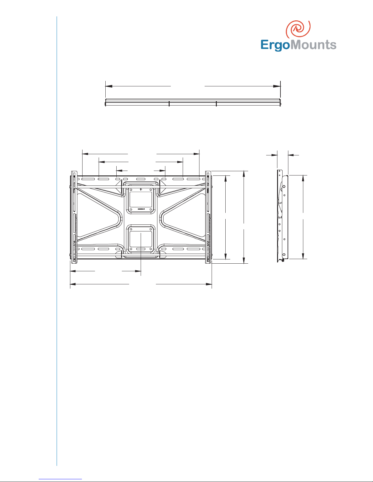
Raise the at panel with the mounting brackets
secured to the at panel and insert the top and
bottom hooks from each bracket to the rods from
the wall plates.
NB Do not over tighten the M6 screws to the rods.
Lateral Shift Adjustment
Locate the two (2) mounting holes that are on the
bottom of each mounting bracket arm.
Insert and tighten two (2) M6 x 30mm lateral shift
locking screws.
Make any lateral shift adjustments at this time. Once
the desired position has been determined, use a
Phillips tip screwdriver and tighten the two lateral
shift locking screws.
NB Although not depicted in the illustrations shown,
the width of this wall mount will encompass two
wall studs.
Safety Knurl Knob Installation
Tilt the at panel and secure two (2) M6 x 12mm
safety knobs to each of the mounting brackets.
Removing the Display from the Wall
Perform the following steps to remove the at panel
from the wall mount.
Extend the display to its maximum tilt range.
Remove the two M6 x 12mm safety knurl knobs.
Push the at panel back to its at position.
Loosen or remove the two (2) M6 x 30 lateral shift
screws.
Lift the unit o the wall plate.
Securing the Plasma to the Wall Mount
1
2
3
1
1
2
3
4
5
Page 7
Technical Speci cations
26.59 (675.49)
19.09 (484.99)
11.09 (281.79)
16.12 (409.57)
32.25 (819.15)
19.00 (482.60)
21.00 (533.40)
19.00 (482.60)
2.45 (62.19)
32.25 (819.15)
Page 8

ErgoMounts Limited
Unit 10
Pegasus Court
North Lane
Aldershot
Hampshire
GU12 4QP
United Kingdom
T +44 (0)1252 333326
F +44 (0)1252 330006
www.ergomounts.co.uk
© ErgoMounts 2010
See it your way...
 Loading...