

Page 1
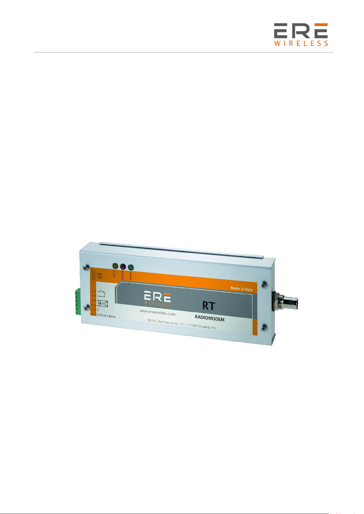
D2 Series
User Guide, Rev. 00 (Feb 2015)
RADIOMODEM
D2 Series
ERE SRL
Via Ermanno Ge, 9/11 | I - 27049 Stradella (PV)
Phone +39 0385 48139 | Fax +39 0385 40288
e-mail:l [email protected]
website: www.erewireless.com
1
Page 2

D2 Series
User Guide, Rev. 00 (Feb 2015)
Table of contents
Table of contents 2
Disclaimer 3
Technical support 3
Restrictions on use 3
Technical specification 4
Conformity declaration 5
Warranty - Liability of the Product 7
Warnings and safety instructions 8
Disposal of waste by users in private households within the European Union 8
General description 9
Installation 10
Mechanical 10
Electrical (wiring) 10
Antenna 11
Configuration 12
Channel selection 12
Software configuration 13
System Requirements 13
Preliminary Operations: 13
RTX configuration 14
Basic configuration 16
Advanced configuration 17
Remote configuration 19
2
Page 3
D2 Series
User Guide, Rev. 00 (Feb 2015)
Disclaimer
All rights to this manual are owned solely by ERE Srl (referred to in this user guide as ERE).
All rights reserved. The copying of this manual (without the written permission from the owner) by
printing, copying, recording or by any other means, or the full or partial translation of the manual
to any other language, including all programming languages, using any electrical, mechanical,
magnetic, optical, manual or other methods or devices is forbidden.
ERE reserves the right to change the technical specifications or functions of its products, or to
discontinue the manufacture of any of its products or to discontinue the support of any of its
products, without any written announcement and urges its customers to ensure, that the information
at their disposal is valid.
ERE software and programs are delivered ”as is”. The manufacturer does not grant any kind of
warranty including guarantees on suitability and applicability to a certain application. Under no
circumstances is the manufacturer or the developer of a program responsible for any possible
damages caused by the use of a program. The names of the programs as well as all copyrights
relating to the programs are the sole property of ERE. Any transfer, licensing to a third party, leasing,
renting, transportation, copying, editing, translating, modifying into another programming language
or reverse engineering for any intent is forbidden without the written consent of ERE.
Technical support
Our website www.erewirless.com contains many useful information, user guides and configuration
software and technical documents always update to the latest version.
If you have technical problems or cannot find the required information in the provided documents,
contact our Technical Support by email at [email protected] or by phone +39 0385 48139
Restrictions on use
ERE PRODUCTS HAVE NOT BEEN DESIGNED, INTENDED NOR INSPECTED TO BE USED IN ANY LIFE
SUPPORT RELATED DEVICE OR SYSTEM RELATED FUNCTION NOR AS A PART OF ANY OTHER CRITICAL
SYSTEM INCLUDED AERONAUTICAL / AEROSPACE APPLICATION.
ERE PRODUCTS ARE GRANTED NO FUNCTIONAL WARRANTY IF THEY ARE USED IN ANY OF THE
APPLICATIONS MENTIONED.
ERE D2 (RT) Series radio modems have been designed to operate on frequency ranges with
permission of frequency management authority. The user of a radio modem must take care that the
device is not operated without the permission of the local authorities on frequencies other than
those specifically reserved and intended for use without a specific permit.
3
Page 4
D2 Series
User Guide, Rev. 00 (Feb 2015)
Operating data
Value
Label
Description
D230
D260
D261
D262
VS
(EXT)
Power supply
12 Vdc
PS
(EXT)
Max power
48W
PRF
Max RF transmission power
2, 5 – 10 W
RX
SENS
Receiver sensitivity
≤ -118 dBm
RF
MOD
Modulation mode
8K50F1D
CH
Channels spacing
12,5
BR Radio
Baud Rate on radio channel
1200, 2400 or 3600 bps
Z
I/O ANT
Antenna impedance
50 𝝮
Digital
Input
Digital input rating
5 – 24 Vdc | 3 – 20 Vac
Z
DIGITAL INPUT
Digital input impedance
2.2 k 𝝮
Digital
Output
Digital output rating
Normalmente aperto (NO)
[email protected] – 32VDC@1A
I
A,B LINES
Max current out at RS-485 serial port
± 60 mA
BR DTE
Baud Rate RS-485 serial port
1.200 → 38.400 bps
Operating band (MHz)
D230
D260
D261
D262
156.000
174.000
440.000
470.000
390.000
420.093
420.000
450.000
Maximum operating data
Label
Description
Value
V
S(EXT)
Max power supply voltage
12 Vdc
V
DIG-INP
Digital input max voltage on
24 Vdc / 20 Vac
V
DIG-OUT
Digital output max voltage rating
32 Vdc / 28 Vac
VP
RS-485
Max peak voltage at the ports A/B RS-485
(1)
± 32 Vdc
IO
DIG-OUT
Digital output max current
1 Adc / 500 mAac
I
A,B LINES
Max peak current at the ports A/B RS-485
(1)
± 200 mA
T
OPERATING
Operating temperature range
-20°C +60 °C
T
STORAGE
Storage temperature range
-40°C +85 °C
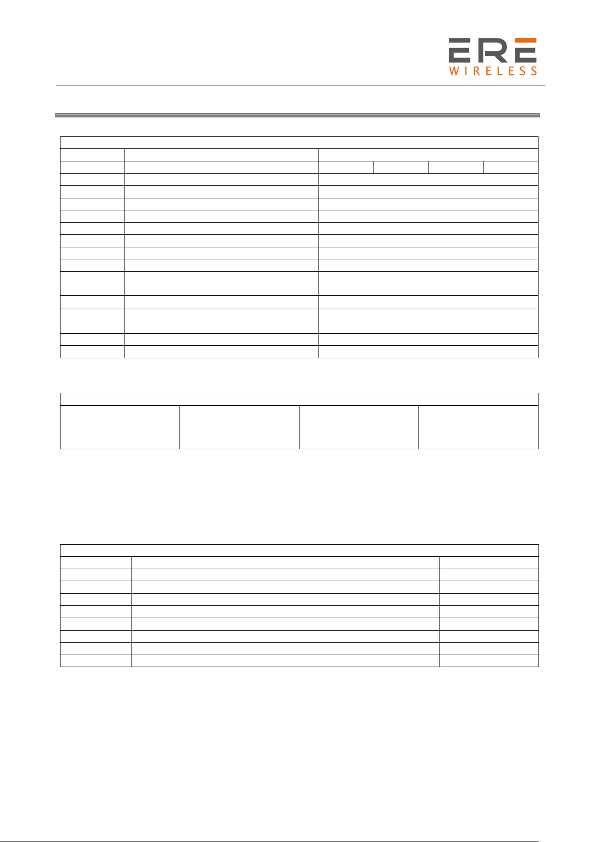
Technical specification
WARNING
Exceed the maximum operating value below (continuous and/or temporary) can damage the
device
NOTE:
(1)
Impulse time < 100 millisecond.
4
Page 5

D2 Series
User Guide, Rev. 00 (Feb 2015)
Conformity declaration
English: Hereby, ERE S.r.l. declares that this D2 SERIES is in compliance with the essential
requirements and other relevant provisions of Directive 1999/5/EC.
Finnish: ERE S.r.l. vakuuttaa täten että D2 SERIES tyyppinen laite on direktiivin 1999/5/EY oleellisten
vaatimusten ja sitä koskevien direktiivin muiden ehtojen mukainen.
Dutch: Hierbij verklaart ERE S.r.l. dat het D2 SERIES in overeenstemming is met de essentiële eisen
en de andere relevante bepalingen van richtlijn 1999/5/EG. Bij deze verklaart ERE S.r.l. dat deze D2
SERIES voldoet aan de essentiële eisen en aan de overige relevante bepalingen van Richtlijn
1999/5/EC.
French: Par la présente ERE S.r.l. déclare que l'appareil D2 SERIES est conforme aux exigences
essentielles et aux autres dispositions pertinentes de la directive 1999/5/CE.
Par la présente, ERE S.r.l. déclare que ce D2 SERIES est conforme aux exigences essentielles et aux
autres dispositions de la directive 1999/5/CE qui lui sont applicables
Swedish: Härmed intygar ERE S.r.l. att denna D2 SERIES står I överensstämmelse med de väsentliga
egenskapskrav och övriga relevanta bestämmelser som framgår av direktiv 1999/5/EG.
Danish: Undertegnede ERE S.r.l. erklærer herved, at følgende udstyr D2 SERIES overholder de
væsentlige krav og øvrige relevante krav i direktiv 1999/5/EF
German: Hiermit ERE S.r.l., dass sich dieses D2 SERIES in Übereinstimmung mit den grundlegenden
Anforderungen und den anderen relevanten Vorschriften der Richtlinie 1999/5/EG befindet". (BMWi).
Hiermit erklärt ERE S.r.l. die Übereinstimmung des Gerätes D2 SERIES mit den grundlegenden
Anforderungen und den anderen relevanten Festlegungen der Richtlinie 1999/5/EG. (Wien)
Greek: ΜΕ ΤΗΝ ΠΑΡΟΥΣΑ ERE S.r.l. ΔΗΛΩΝΕΙ D2 SERIES ΣΥΜΜΟΡΦΩΝΕΤΑΙ ΠΡΟΣ ΤΙΣ ΟΥΣΙΩΔΕΙΣ ΑΠΑΙΤΗΣΕΙΣ ΚΑΙ
ΤΙΣ ΛΟΙΠΕΣ ΣΧΕΤΙΚΕΣ ΔΙΑΤΑΞΕΙΣ ΤΗΣ ΟΔΗΓΙΑΣ 1999/5/ΕΚ
Italiano: Con la presente ERE S.r.l. dichiara che D2 SERIES è conforme ai requisiti essenziali ed alle
altre disposizioni pertinenti stabilite dalla direttiva 1999/5/CE.
Spanish: Por medio de la presente ERE S.r.l. declara que el D2 SERIES cumple con los requisitos
esenciales y cualesquiera otras disposiciones aplicables o exigibles de la Directiva 1999/5/CE
Portuguese: ERE S.r.l. declara que este D2 SERIES está conforme com os requisitos essenciais e
outras disposições da Directiva 1999/5/CE.
5
Page 6
D2 Series
User Guide, Rev. 00 (Feb 2015)
Company
ERE S.r.l.
Address, City
Via Ermanno Ge, 9/11 - 27049 Stradella (PV)
Country
Italy
Phone number
+39 0385 48139
Fax number
+39 0385 40288
Product description / Intended use
156-174 MHz and 390-470 MHz
Radiomodem for commercial and lightindustrial use
EU / EFTA member states
intended for use
EU: all members
EFTA: all members
Member states with restrictive use
EU: all members
EFTA: all members
Manufacturer
ERE S.r.l. | I-27049 Stradella (PV)
Brand name
ERE
Type/Model
D2 SERIES
Art. of Directive
Standard
Date of issue of the standard
3.1(a) Health
EN 50401
2006 + A1(2011)
3.1(a) Safety
EN 60950-1
2006 + A11:2009 + A1:2010 +A12:2011 +AC:2011
3.1(b) EMC
EN 301 489-1
V1.9.2 (2011-09)
3.1(b) EMC
EN 301 489-3
V1.6.1 (2013-08)
Art. of Directive
Standard
Date of issue of the standard
3.2 Spectrum
EN 300 220-2
V2.4.1 (2012-05)
TCF reference nr.
D1 SERIES Rev.0
Data
18 febbraio 2015
Sign
Name and position
Giovanni Soldo - CEO
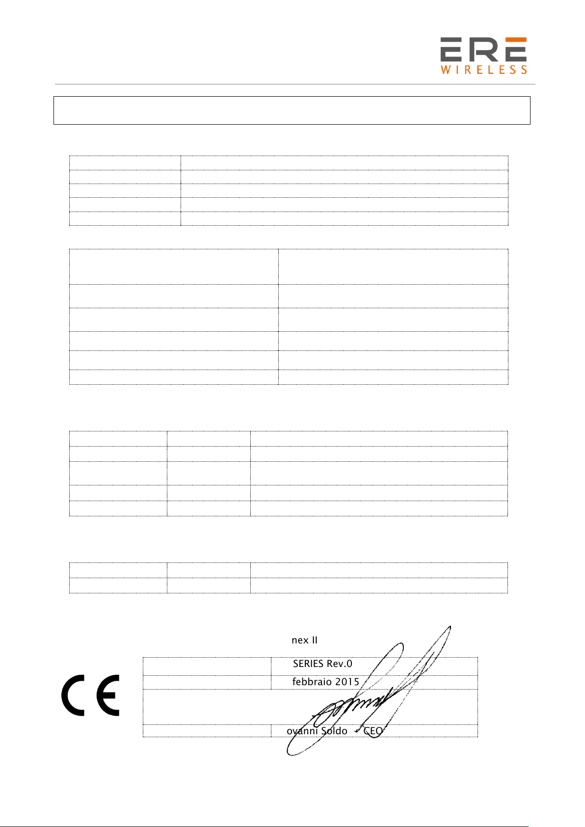
Declaration of Conformity
We, the undersigned,
certify and declare under our sole responsibility that the following equipment:
is tested to and conforms with the essential requirements for protection of health and the safety of
the user and any other person and Electromagnetic Compatibility, as included in following
standards:
and is tested to and conforms with the essential radio test suites so that it effectively uses the
frequency spectrum allocated to terrestrial/space radio communication and orbital resources so to
as to avoid harmful interference, as included in following standards:
and therefore complies with the essential requirements and provisions of Art. 3.3 too, where
applicable, of the Directive 1999/5/EC of the European Parliament and of the council of March 9,
1999 on Radio equipment and Telecommunications Terminal Equipment and the mutual recognition
of their conformity and with the provisions of Annex II
6
Page 7

D2 Series
User Guide, Rev. 00 (Feb 2015)
Warranty - Liability of the Product
Supplier represents and warrants that products are manufactured in accordance with the applicable
specifications and are free from defects in materials and workmanship. The warranty, valid for a
period of 12 months of use, maximum 18 months from the date of delivery, shall not cover defects
caused by accident, Buyer’s negligence, improper use or maintenance or by any other reason beyond
Supplier’s control.
Buyer shall have 10 (ten) working days following receipt of products to inspect the products and to
notify to Supplier in writing any defects or non-compliance. In the event that any shipment of
products is not accepted by Buyer due to any non-conformity with the specifications, or as a result
of a cause occurred prior to placement thereof with the carrier, Buyer shall, if so indicated in writing
by the Supplier, promptly return some samples or the full shipment that was rejected by Buyer at
Buyer’s costs.
Supplier, at its own discretion, shall, within a reasonable period, considering the entity of the
complaint: (i) send a replacement shipment of products conforming, or (ii) credit Buyer a sum equal
to the value of the defective or non-conforming products. This warranty overwrites all legal
warranties for defects and compliance and exempts Supplier from any other responsibility for the
supplied products; in particular, Buyer shall not be entitled to any requests for compensation or
price reductions.
If one of the products sold by the Supplier to the Buyer is defective, the Buyer will send it, at its own
expense, at the headquarters of the Italian Supplier. The product will be repaired or replaced by the
Supplier, at no costs to the Buyer.
The Buyer will pay all the shipping costs for the product repaired or replaced and sent back to the
Buyer.
The Buyer will bear all costs related to disassembly, assembling and transportation of the product,
and any damage caused by the "machinery inactivity".
Supplier shall indemnify Buyer against any liability of the products claims asserted by third parties
relating to damages sustained as a result of a defective products. In such case Supplier shall
reimburse Buyer exclusively within the limits, terms and conditions of the products liability insurance
policy held by Supplier. Buyer shall not make any oral or written representations which vary from
the specifications, operating instructions, labels or representations given or made by Supplier with
respect to the products. If any liability is incurred because of such varying representations, Buyer
holds Supplier harmless with respect to any such representations.
In no event shall Supplier be liable for any indirect, incidental, exemplary or consequential damages,
including without limitation any claim for damages based on lost revenues or profits, however
caused.
In no event shall the Supplier be liable for any costs or damages arising from any act or omission of
Buyer, including, without limitation, relating to the modification, handling, storage and marketing
of Products by Buyer or to Buyer’s failure to provide its employees, agents and customers or other
third parties with adequate instruction as to the proper handling and use of Products.
In this respect we hereby confirm that our products are not designed for nuclear applications neither
for aircraft/aerospace industries. For the above mentioned applications both warranty and insurance
coverage do not apply.
7
Page 8
D2 Series
User Guide, Rev. 00 (Feb 2015)
Warnings and safety instructions
-Read these safety instructions carefully before using the product:
-Warranty will be void, if the product is used in any way that is in contradiction with the instructions
given in this manual, or if the radio modem housing has been opened or tampered with.
-The radio modem is only to be operated at frequencies allocated by local authorities, and without
exceeding the given maximum allowed output power ratings and duty cycle. ERE and its distributors
are not responsible, if any products manufactured by it are used in unlawful ways.
-The devices is complies with Directive 1999/5/EC as describe in our declaration of conformity above
-The devices mentioned in this manual are to be used only according to the instructions described
in this manual. Faultless and safe operation of the devices can be guaranteed only if the transport,
storage, operation and handling of the devices is appropriate. This also applies to the maintenance
of the products.
-Do not install the equipment close to a heat source or in damp conditions and direct sunlight is
also to be avoided.
-The device must not be exposed to aggressive chemical agents or solvents likely to damage the
plastic or corrode the metal parts.
-The device must not be exposed directly to dusty environment.
-Maintenance should only be carried out by qualified persons.
-For your own safety, you must ensure that the equipment is switched off before carrying out any
work on it.
-Any electrical connection of the product must be equipped with a protection device against voltage
spikes and short-circuits
Disposal of waste by users in private households within the European Union
For further information concerning your nearest recycling centre, please contact your nearest local
authority/town hall offices.
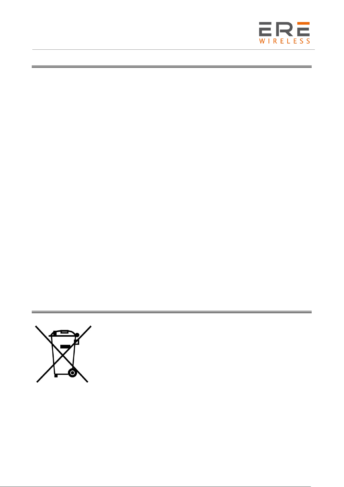
According to Directive 2012/19/EU of the European Union on waste electrical
and electronic equipment (WEEE) this product must not be disposed off with
your other household waste, it is your responsibility to dispose of your waste
by taking it to a collection point designated for the recycling of electrical and
electronic appliances.
Separate collection and recycling of your waste at the time of disposal will
contribute to conserving natural resources and guarantee recycling that
respects the environment and human health.
8
Page 9
D2 Series
User Guide, Rev. 00 (Feb 2015)
Operating mode
Radio modem
Radio
Channel spacing
Yes
RF channel
Yes by DIP switch
Frequency Agility
Yes
Listen Before Talk
Yes
RF power
D230, D260, D261, D262
Porta Seriale
RS485 or RS232
Configurable by DIP switch
Bit Rate
Yes
Parity bit
Yes
DTX Time
Yes
Data
Routing Table
Standard 1, with address from DTE up to 8
Broadcasting
Yes
Address from DTE
Yes
Address to DTE
Yes
Rx address for Tx
Yes
Request of ACK
Yes
Set number of retries
Yes
NAK to DTE
Yes
Routing Table
Yes
Other
Diagnostic
Yes
Power Save
Yes
Link Test
Yes
General description
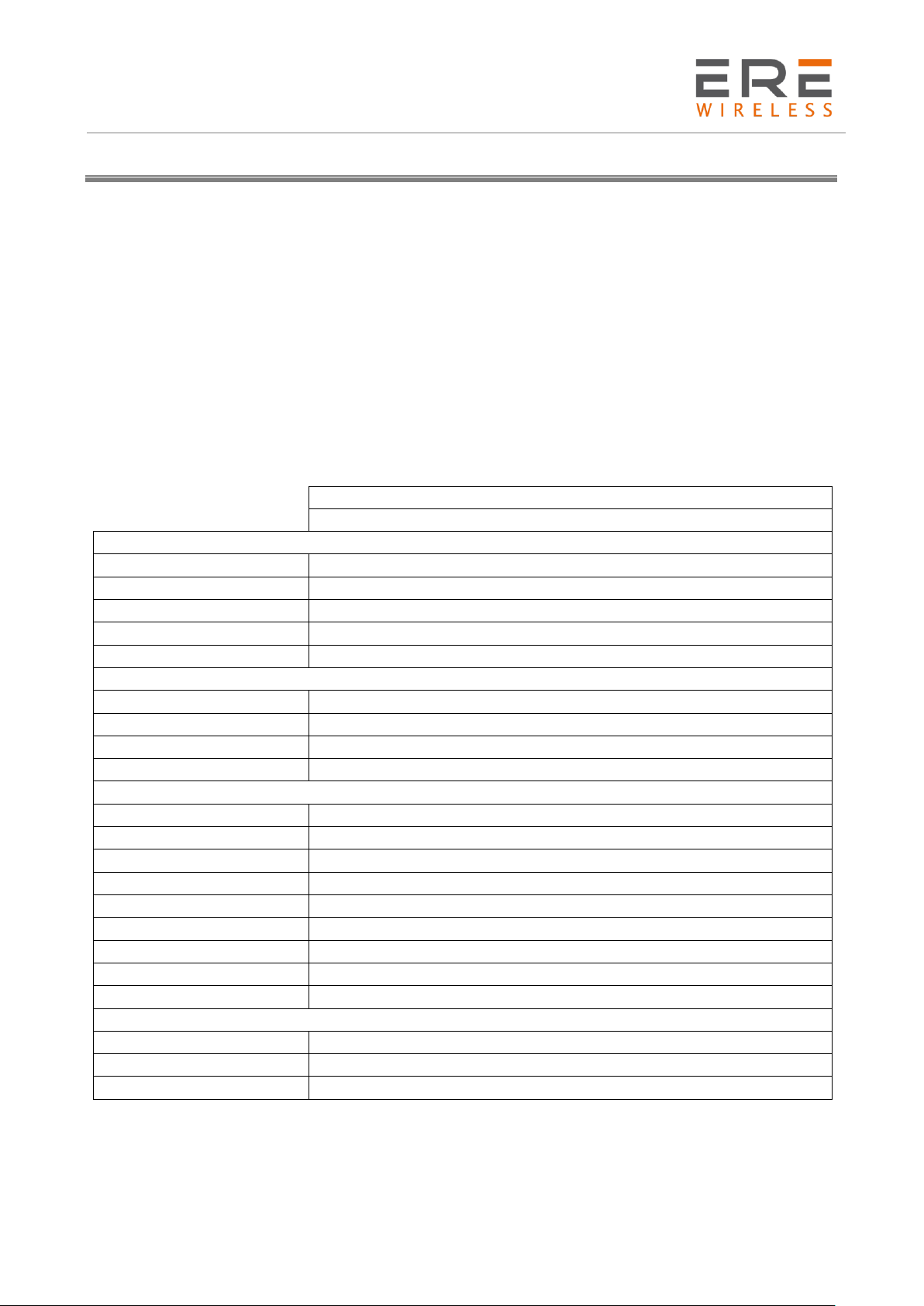
The D2 Series (RT) are radiomodems with RS232 and RS485 serial connections, configurable by
software, either remotely or locally, on the fly by DTE.
The devices are complete with one optically isolated digital input and one relay output that can be
used for radio transmission of signal and alarms.
Four operating modes that are software programmable: mirror point to point, point to multipoint,
broadcasting, and digipeater which allows multipath data routes, to ensure data delivery.
The Low power design along with the power saving function, allows for extended battery life.
Robust construction with surface mounted components, ensure highly-stable electronics.
Optional antenna configurations can improve radio transmissions where radio coverage is critical
9
Page 10
D2 Series
User Guide, Rev. 00 (Feb 2015)
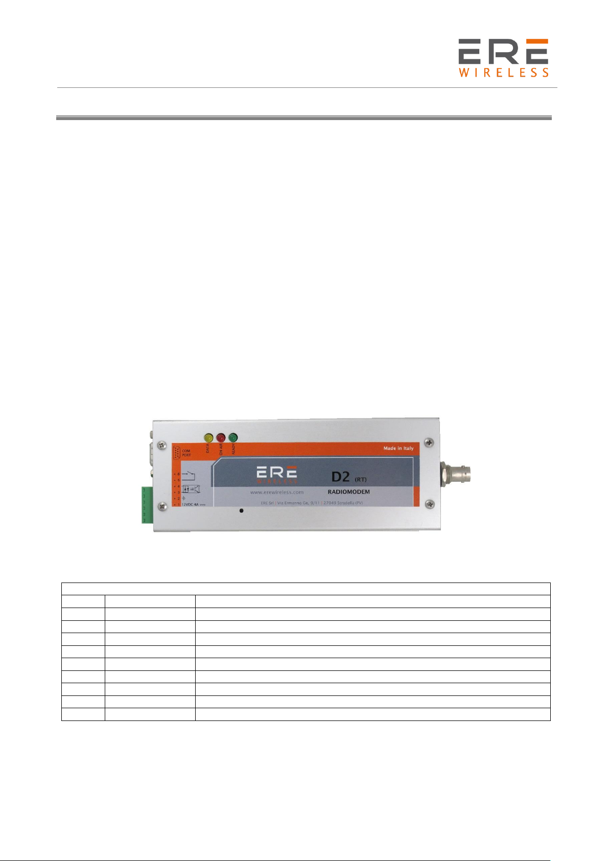
JP1 Connector
PIN
Label
Description
1
A RS485
RS-485 (line A)
2
RXD (OUT)
Data output (RS232)
3
TXD (IN)
Data input (RS232)
4
DTR
Data Terminal Ready (RS232)
5
GROUND
Ground (GND) (RS232)
6
DSR
Data Set Ready
7
RTS
Request To Send (RS232)
8
CTS
Clear To Send (RS232)
9
B RS485
RS-485 (line B)
JP1
JP2
Installation
Mechanical
The device must be installed in a location that is sufficiently ventilated so that there is no risk of
internal heating. Place the device against a flat, firm and stable surface. It is not recommendable to
install the radio modem on a strongly vibrating surface. Suitable dampening and/or isolation
materials should be used in cases where the installation surface will be subjected to vibration.
Electrical (wiring)
To prevent damage both the radio modem and any terminal devices must always be switched OFF
before connecting or disconnecting the serial connection cable. It should be ascertained that
different devices used have the same ground potential. Before connecting any power cables the
output voltage of the power supply should be checked.
The product has no disconnecting device. An external disconnecting device must be installed. This
must be close to the equipment.
To by supplied by class II (LPS) certified AC/DC adaptor.
10
Page 11
D2 Series
User Guide, Rev. 00 (Feb 2015)
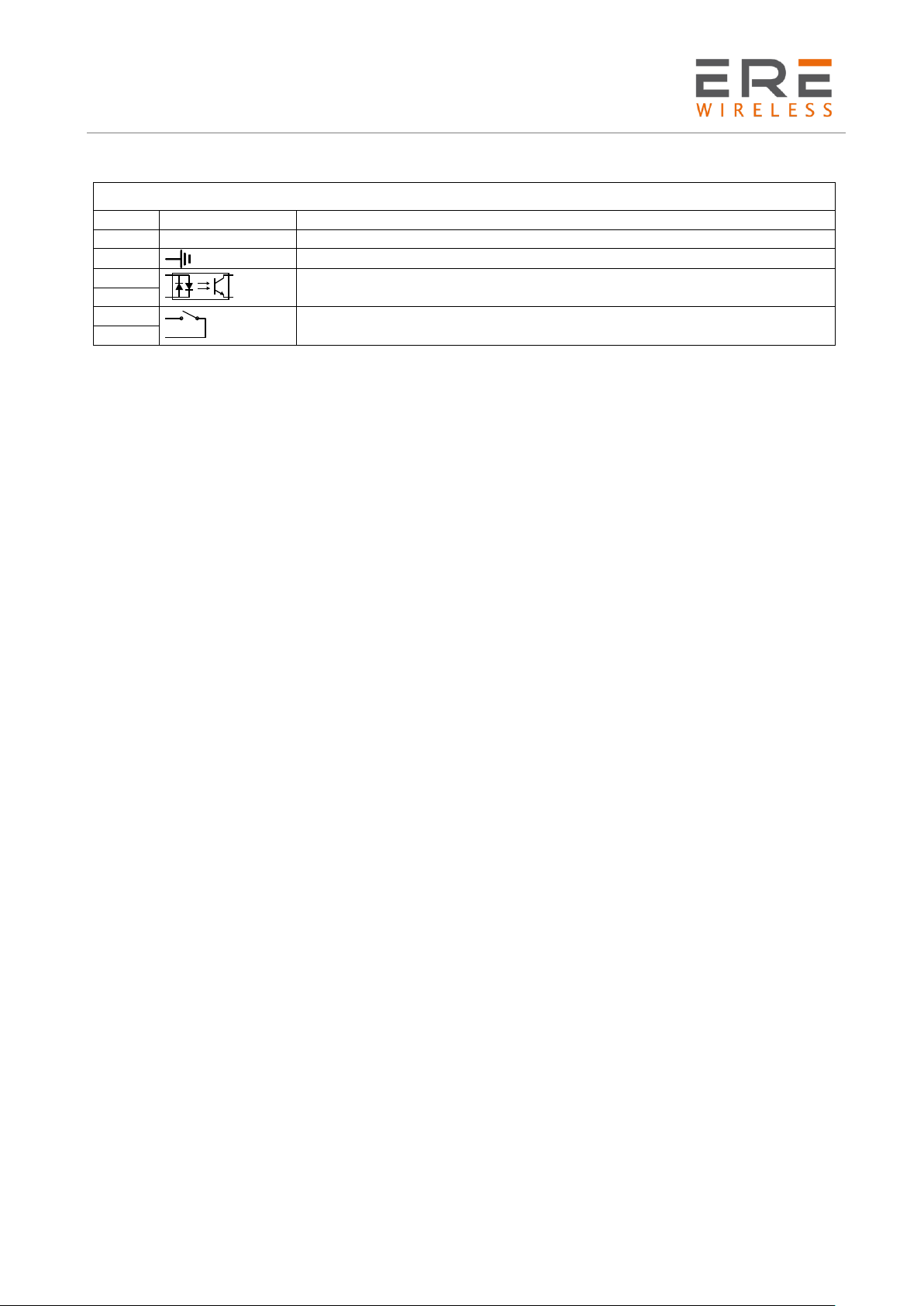
JP2 Connector
PIN
Label
Description
1
12V 4A
Power supply (12 VDC, 4A)
2 Ground (GND)
3
Optoisolated digital input
4
5
Digital output normally open (NO)
6
Antenna
The device’s antenna must be free and at least 10 cm away from any conducting material. When the
antenna is installed outside, it is essential to connect the cable screen to the building’s earth. We
recommend using lightning protection. The protection kit chosen must permit the coaxial cable to
be earthed (eg: coaxial lightning arrester with earthing of the cable at different places on the antenna
at the base of pylons and at the entry, or just before entering the premises).
11
Page 12
D2 Series
User Guide, Rev. 00 (Feb 2015)
Channel
S1 Dip 1
S1 Dip 2
S1 Dip 3
1
OFF
OFF
OFF 2 ON
OFF
OFF
3
OFF
ON
OFF 4 ON
ON
OFF
5
OFF
OFF
ON
6
ON
OFF
ON 7 OFF
ON
ON 8 ON
ON
ON
S1
Configuration
Channel selection
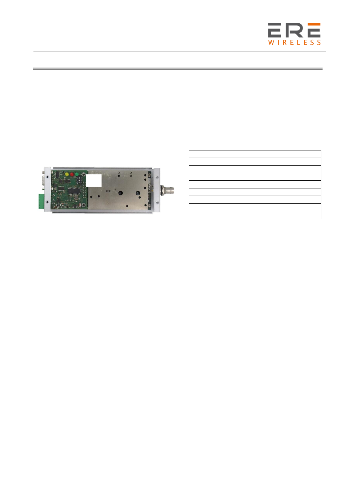
The channel selection may be done in Hardware mode or in software mode, through the linked DTE.
1 – Hardware Channel Selection
The Hardware channel selection is the default mode. The choice is done by the dip-switches bank.
The eight available channels are selected by the 1st, 2nd, and 3rd switch while the 4th is inactive.
2 – Channel Selection by DTE
This feature is available only if the Addr from DTE option is selected in all operating modes
comprehending the Broadcasting one. The initial requirement is the complete configuration of all
the eight available channels. To change the channel is sufficient to send to the radiomodem unit the
following hexadecimal string containing only 3 bytes:
New channel number(h) – 09h – New channel number(h).
At the end of the sending wait at least 1 millisecond before use the unit in the normal operation
mode. To restore the manual selection the required hexadecimal string is 00h – 09h – 00h. The
change by DTE is not stored in the radiomodem memory therefore its reset restores the default
manual selection.
3 – Channel Selection of a Remote Unit using the Master Unit and the Radio Network.
In the standard applications one or more peripherals may be placed in a “problematic” site essentially
due to logistic difficulties.
To avoid this problems a Remote Programming/Channel selection utility is installed into the
configuration software.
The programming procedure is exhaustively explained below under the Remote Configuration
paragraph.
12
Page 13
D2 Series
User Guide, Rev. 00 (Feb 2015)
Software configuration
Download from ERE web site (www.erewireless.com) the latest version of configuration software
(confSW_D1).
The configuration must be done through a RS232 interface
System Requirements
Operative System: Windows 98 SE, Windows ME, Windows2000, Windows XP, Windows Vista,
Windows 7
Minimum screen resolution: 800 x 600 dpi.
Preliminary Operations
Connect with a right cable (NO Null Modem) the serial port of the personal computer (COM1 or
COM2 depending on the personal computer characterisation) to the serial port of the Radiomodem
and successively start the program.
Push the Option label to select the serial port and the operative band of the radiomodem. The
band choice must be congruent with the radiomodem characteristics.
Connect the radiomodem supply (+12,5 Vdc) and push the Power ON button in the configuration
software to enable the computer serial port. In this way the DTR criteria turns on the radiomodem
and simultaneously the Power on button disappears after the serial port activation. Turning on the
unit, the radiomodem checks itself and if a previous configuration is installed, the Ready Led
(green) is turned on otherwise it blinks. During the production checks the test configuration is
installed and stored in the modem, so the green led is normally turned on at the end of the
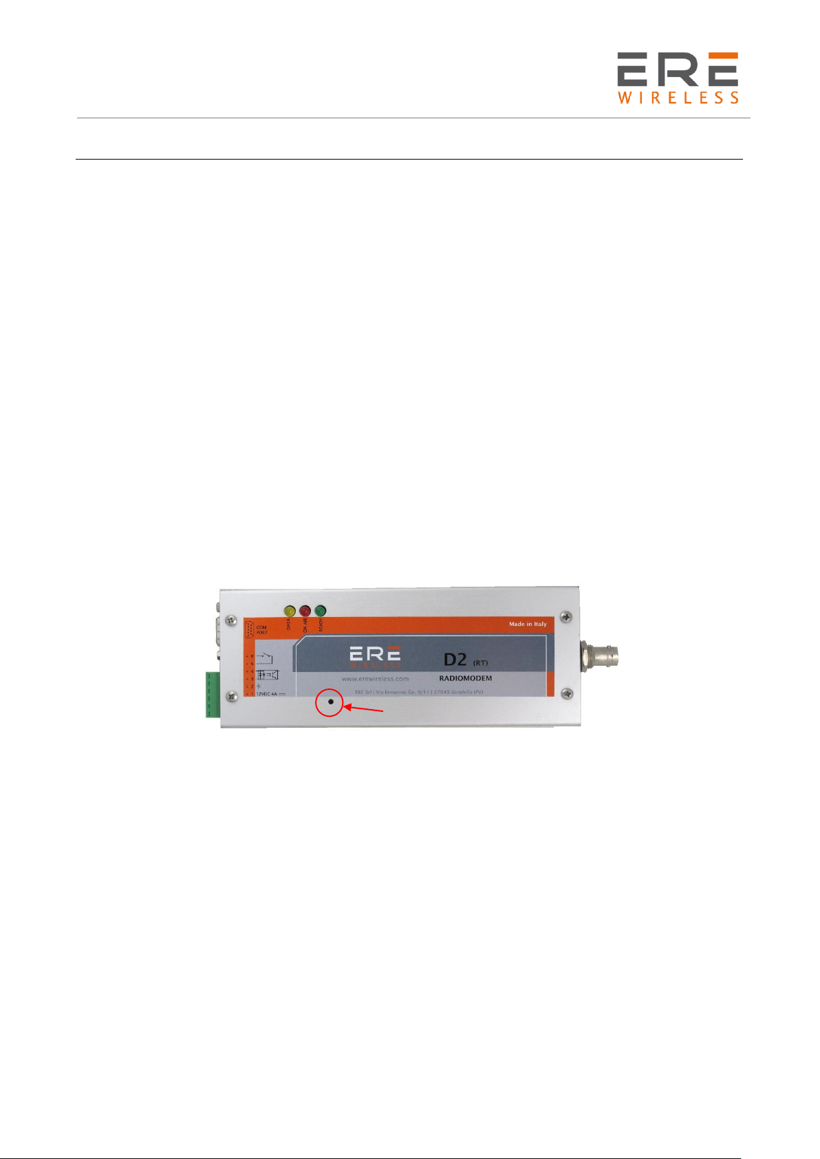
initialisation process. To install a new configuration push the Configuration switch on the modem
board, for at least two seconds, to force it in the Configuration Mode.
In this condition the Ready Led (green) is turned on while the Data Led (yellow) is blinking.
The field selection is possible using the TAB and Up, Down, Left and Right arrow keys. An option
is activated when the related box is selected otherwise is inactive.
After the modem configuration, push, for at least two seconds, the Configuration switch on the
board to restore the operative condition and quit from the program. In this mode the Ready Led
(green) is turned on while the Data Led (yellow) is turned off.
13
Page 14
D2 Series
User Guide, Rev. 00 (Feb 2015)
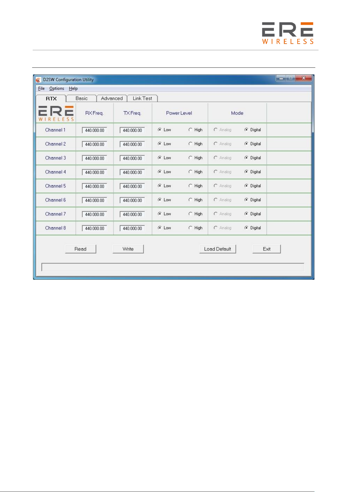
RTX configuration
Fields specifications.
The Field characteristics are specified as follows. In the square brackets [ ] are indicated the
permitted values or the activation ON/OFF while in the round brackets is indicated the measure
unit.
RxFreq. (MHz) : The receiving frequency in MHz of the selected channel. The inserted value must
be compatible with the operative band of the radiomodem. The synthesis step is of 6.25 kHz. If the
inserted value is not an exact multiple of 6.25 kHz, an automatic rounding off to the nearest value
is performed. The insertion format is 434.156.25 for a frequency of 434.15625 MHz. The F5 and
F6 keys may be used to decrease, respectively increase, the displayed frequency of a 6.25 kHz step.
TxFreq. (MHz) : The transmitting frequency in MHz of the selected channel. All considerations valid
for the RxFreq. are applicable to this parameter. The RxFreq. and the TxFreq. may be different, if
requested.
Power Level : To select the desired RF Output Power
Mode : In the use with the Modem Plug-in this field is Digital and may not be changed.
Read button : Push to read the configuration stored in all the eight available channels.
Write button : Push to write the new or the modified configuration in all the eight available channels.
Power On : Push to enable the selected serial port of the computer and the turning on of the
radiomodem. This button is visible only at the program start, at the serial port change and at the
opening of a previously stored configuration file. After the utilisation this button disappears.
14
Page 15

D2 Series
User Guide, Rev. 00 (Feb 2015)
Load default : Push to load a default values in the fields of all available channels. These values may
be modified.
Exit : Push to quit the configuration program.
Toolbar.
The toolbar on the top side contains the File, Options and Help menus. Each menu may be opened
by the mouse or using the ALT key plus the underscored letter as usual in Windows. The features
of the various menus are the following:
Menu FILE:
- Open (path/filename) : To load in the configuration software all the parameters previously saved
in a file.
- Save : To update a current file with all modifications.
- Save as (path/filename) : To save all settings in a new file. The user must give a specific name so
this file may be reopened if necessary. The saved files are stored in the same folder containing the
software.
Menu OPTIONS:
- Serial Port Selector [COM1/2] : To select the desired communication port between the available
on the computer
- Band Selector [1,2,3] : Show the operative band. If the radiomodem is never been configured is
possible to change the operative band, otherwise the radiomodem impose the operative band in the
software.
- Protocol : To select the operative protocol of the modem. The possible choices are the RMO400
compatible (internal buffer = 256 byte) or as RT415-M, with 640 bytes of internal buffer and the
Alarm management.
Menu HELP:
- Index F1 : Open the Help File and permit the choice between the Italian or the English version.
- About : To open the software information windows.
Copy and Paste.
To copy the parameters from a channel into an other, select the channel to be copied positioning
the cursor over the Channel N and press the right button of the mouse to choose Copy. To paste
the copied data, select the destination channel positioning the cursor over the Channel N of the
selected channel and press the right button to choose Paste. To copy the selected data into all the
remaining channels, press the right button choosing Paste to all.
15
Page 16
D2 Series
User Guide, Rev. 00 (Feb 2015)
Basic configuration
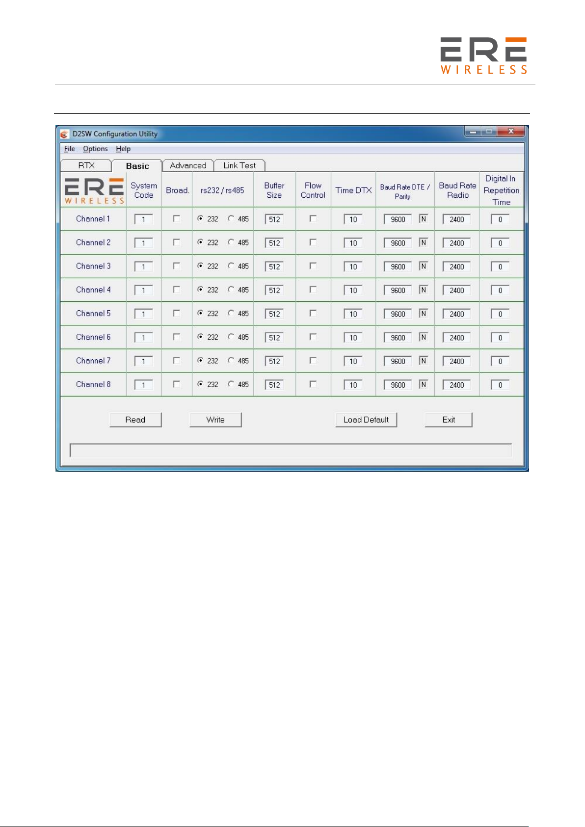
The Basic menu contains the fundamental parameters of the communication between two or more
radiomodem units.
System Code [ 0....63 ] : It's the network identifier. Of course all the units in the network must have
the same System Code
Broadcasting [ON/OFF] : If selected, the radiomodem transmits a message can be received by all
the units having the same System Code, independently from the target address. This option is
allowable only if ACK and Echo are disabled.
RS-232 / RS-485 : To select the desired serial port standard. The Flow Control is available only for
RS-232.
Buffer Size [1..640 /256] : To select the desired internal buffer size. The available sizes vary from
1, without the Flow Control, or 5, with the Flow Control, to a maximum of 640 bytes. In the
RMO400 Compatible Mode this size is set to 256 bytes in according with the RMO400 series
parameters.
Flow Control [ON/OFF] : If selected, the RTS and CTS criteria of the RS-232 serial port manage the
data flow from the DTE. If inactive, the DTE must manage the correct timings between the packets.
TimeDTX [0...255] : Defines the time interval, in milliseconds, between the end of the received data
on the com port and the start of the radio transmission. If an incomplete message is sent, increase
this time to mask the intervals between the bytes in the incoming message.
Baud Rate DTE [1,200/2,400/4,800/9,600/19,200/38,400] (bps) : To select the serial port speed.
16
Page 17
D2 Series
User Guide, Rev. 00 (Feb 2015)
Baud Rate Radio [2,400/3,600/4,800] (bps) : To select the Radio link data speed. Choose the 4,800
bps only for high SINAD networks, e.g. with aerials in optical view and adequately high on the earth
surface.
Parity [N,E,O] : Permits the Parity Bit utilisation in Odd (O) mode or in Even (E) mode. If N (No
parity) is selected the message frame must contain only 8 bits.
Digital IN Repetition Time [1..60] (minutes) : To set the repetition time interval between two
successive refreshes of the Digital input status. The value 0 inhibit the periodic refresh but, in all
cases, this status is sent at every change of the digital input and/or at every data transmission with
the exception of the Broadcasting Mode.
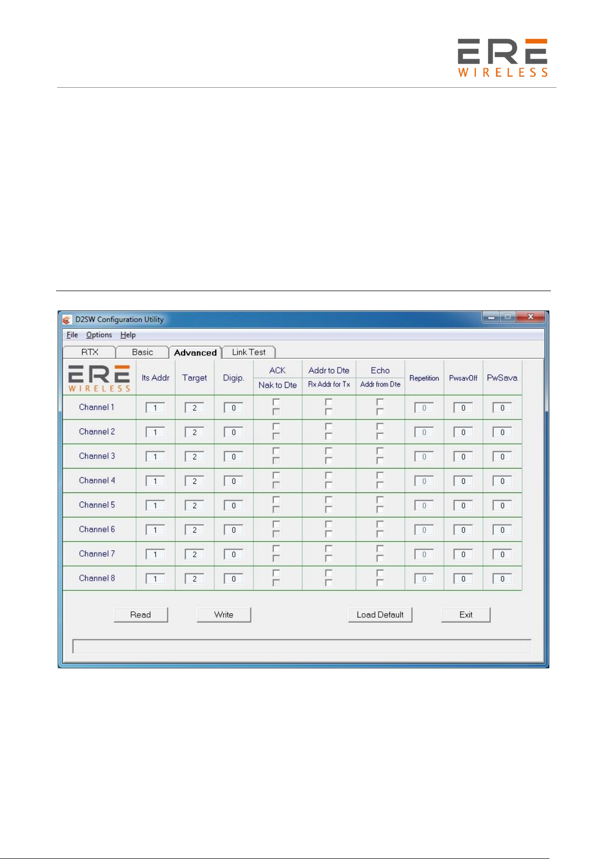
Advanced configuration
Its Addr [1..255] : It is the address of the unit. In a point - multipoint network the Master unit
must have Its Address = 1.
Target [1..255] : The address of the destination radiomodem. In the Broadcasting Mode the
inserted value is not considered while in the Address from DTE Mode it is furnished by the DTE. A
valid value must be inserted in this field independently from the utilisation mode.
Digip. [0..255] : The address of the unit used as repeater. If a network don't contain a repeater, the
value in this field must be set to 0.
17
Page 18

D2 Series
User Guide, Rev. 00 (Feb 2015)
ACK [ON/OFF] : Available only if the Broadcasting and Echo options are inactive. If selected, the
sending unit waits an answer message from the target unit. If this answer is received before an
adequate time-out, the sending unit transmit the next message, otherwise repeats the same until a
valid answer from the target unit will be received. The maximum number of repetition of the
message is set in the Repetion field.
NAK to DTE [ON/OFF] : Available only if ACK is activated. At the end of the repetition cycle if no
answer from target unit is received, the NAK character (ASCII 21) is sent to the DTE.
Addr to DTE [ON/OFF] : If selected, the data sent to the DTE are preceded by the address of the
sending unit. Rx Addr for Tx [ON/OFF]: Available only if Addr from DTE is inactive. If selected,
the unit stores the entire addressing data (source unit plus all digipeaters if used) of the last
incoming message and reutilises them for the answer.
Echo [ON/OFF] : Available only if ACK and Broadcasting are inactive. It's a simply utility to verify
the radio link. If selected, the target unit receiving an "Echo" message don't release it to its serial
port but repeat it to the source unit that releases the message to its DTE.
Addr from DTE[ON/OFF]: Available only if Rx Addr for Tx is inactive. If selected, the DTE must
manage the addressing of the message. The correct addressing is obtained sending, before of each
message, the appropriate address string. The addressing string contains from 3 to 11 bytes
depending on the route complexity. The necessary bytes are the following:
The 1st is the System Code byte where the two most significant bits are the Broadcasting switch
(bit No. 7) and the Echo switch (bit No. 6). The admissible values are 1...63.
The 2nd byte is the Number of units in the route comprehending the target and all the digipeaters.
The admissible values are 1...9 equivalent to one target unit and up to 8 digipeaters.
The successive bytes are the digipeaters addresses listed in the exact sequence of use.
The last addressing byte is the target address.
Finally the message to be sent with a maximum of 640 bytes or 256 bytes for the use in the
RMO400 Compatible mode.
Repetition [0..255] : Available only if the ACK function is activated. It set the maximum number of
the repetition of the message if the answer from the target is not received.
PwSavOFF [0..240] : The OFF time, in steps of 10 milliseconds, in the Power Saving Cycle. The
related ON time is of 70 milliseconds. This time is used to calculate all the communication timings
therefore must be the same for all the units in the network. If the Power Saving is not desired, set
the PwSavOFF to 0. The maximum allowable PwSavOFF time is of 2.40 seconds.
PwSava [ 0..255] : The waiting time, is steps of 100 milliseconds, to return in the Power Saving
Cycle after any transmitting or receiving cycle. If the Power Saving is not desired, set the PwSava to
0. The maximum PwSava time is 254, equivalent to 25.4 seconds. The value 255 set the unit as
Master in a point-multipoint network. This unit is always active but it can send messages with a
preamble length defined by the PwSavOFF time.
18
Page 19
D2 Series
User Guide, Rev. 00 (Feb 2015)
Remote configuration
The configuration software RT415SW allows the complete configuration of a remote unit through
an other radiomodem unit connected to a Personal Computer. To obtain this functionality the local
unit must be configured under the following procedure.
Connect the local unit to a PC, force it into Configuration Mode, as previously explained, and select
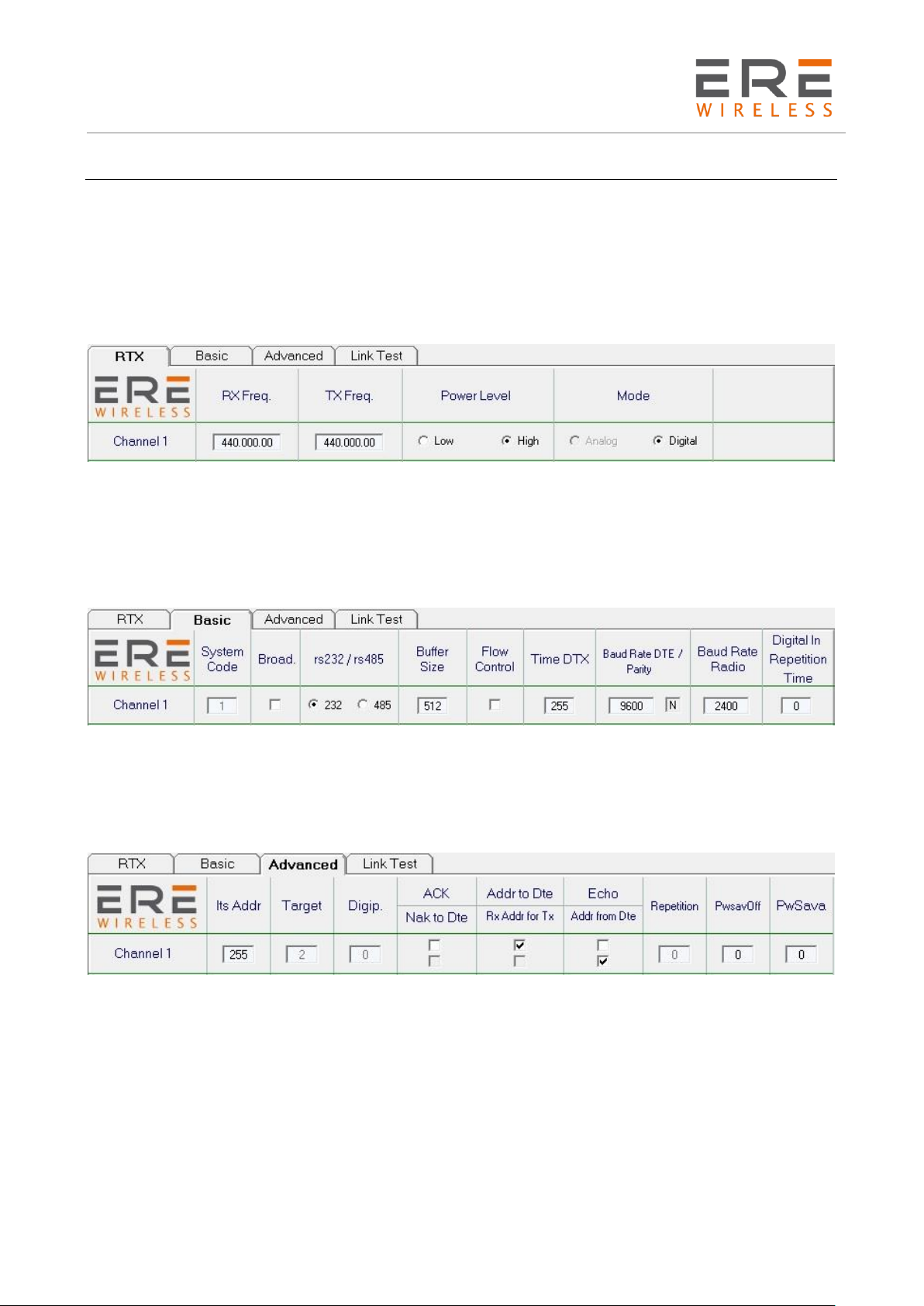
the RTX page from the menu. Insert into RXFreq. and TXFreq. the same values used in the remote
unit to be configured. The Power Level must be set to high.
The following Fig. 1 shows a RTX page configuration example for the local unit.
Select the Basic page and set the following parameters: Deactivate both Broad and Flow Control
options, don’t change the Buffer size (it remains of 512 bytes) and select the RS-232 Interface. Set
to 255 the Time DTX and successively set to 9,600 and N (no parity) the Baud Rate DTE. The Baud
Rate Radio must be set to the same value used in the remote unit to be configured. The Digital In
Repetition Time must be set to 0.
The following Fig. 2 shows a Basic Page configuration example for the local unit.
Select the Advanced Page and set the following parameters: Deactivate both ACK and Echo options,
select both Addr from DTE and Addr to DTE options, set Its Addr = 255 and set both PwSavOFF
and PwSava with the same values of the remote unit to be configured. If the remote unit is
configured in Broadcasting and Power Saving Mode, the PwSava field must be set to 20.
The following Fig. 3 shows an Advanced Page configuration example for the local unit.
Turn off the local unit and set it on the channel N° 1, or in the channel configured for the process,
connect the antenna and turn on the local unit. In the Options menu select the Remote option and,
in the lower side of the page, push the Power On button. To show the remote unit parameters push
the Read button and a dialogue box appears. In this box must be inserted the remote unit
parameters: System Code, the digipeaters addresses in the correct sequence of use, the remote
unit address and, finally, the PwSavOff time used in the remote unit. The value to be inserted in
the System Code depends on the operating mode of the remote unit. If the remote unit is
characterised with the Addr from DTE option, the System Code must be 0 only if no one message
has been sent, otherwise it must be the same of the communication network. In all other operating
modes the System Code must be the same of the network.
Push the Ok button to send the reading request and wait. After few seconds, depending on the total
number of digipeaters, all the remote unit parameters will be shown on the PC.
19
Page 20

D2 Series
User Guide, Rev. 00 (Feb 2015)
Modify the parameters as desired, push the Write button and wait, for a time depending on the
network complexity, the updating acknowledgement.
The update shall be stored in the remote unit after 30 seconds since the end of the process. We
recommend a "Read, Modify and Write" procedure to avoid mistakes in the configuration of the
remote units.
Please remember that a change in the operative frequencies of remote unit involve a new setting of
local unit if the waiting time before saving is expired.
20
 Loading...