

Page 1
ErectAStep
219 Safety Avenue
Andrews, SC 29510
Phone 888-878-1839
Fax 843-264-8584
OWNER’S MANUAL
Page 2
UNIVERSAL MODULAR PLATFORM SYSTEM
WARNING! READ CAREFULLY AND UNDERSTAND ALL INSTRUCTIONS BEFORE STARTING INSTALLATION. FAILURE TO
FOLLOW ALL INSTRUCTIONS MAY RESULT IN DEATH OR SERIOUS PERSONAL INJURY.
IMPORTANT
• Equipment should not be altered or modified from its original design without consultation with the manufacturer.
• Equipment which is damaged or becomes damaged during use, handling, or shipping should be set aside and not used.
• WARNING! Failure to anchor unit properly with the correct layout dimensions can result in product damage not covered under
warranty – product is not designed to be self supported without anchor bolts. Failure to secure all fasteners may result in death or
serious personal injury.
• Do not assemble unit off of anchor bolts and then lift onto them. System should only be assembled in its final location. Never move
an assembled system.
• WARNING! Backing plates must be used where designated in the instruction manual. Failure to use backing plates where
designated may cause equipment to fail and may result in death or serious personal injury.
• TORQUE DATA:
All ½” bolted connections = 678 in-lbs. (56 ft-lbs.) lubricated or 904 in-lbs. (75 ft-lbs.) dry +/-10%.
For 5/8” anchor bolts = 900 in-lbs. (75 ft-lbs.) lubricated or 1080 in-lbs. (90 ft-lbs.) dry +/-10%.
Use of impact wrenches NOT sanctioned.
• WARNING! After a usage period of 60-90 days, check all fasteners to ensure connections are secure. Periodic inspection is
recommended to insure all fasteners are secured. Failure to secure all fasteners may result in death or serious personal injury.
4-29-16
1
Page 3

UNIVERSAL MODULAR PLATFORM SYSTEM
ASSEMBLY CRITERIA
Verify proper installation according to ErectAStep installation manual. In addition, make sure to check the following specifically.
• Ensure all anchor bolts are installed properly at the stair base and tower.
• Ensure leading edge of platform and stair gusset are flush.
• Ensure tower is vertically plumb.
• Ensure all bolts are properly tightened according to ErectAStep installation manual.
– No impact wrenches are to be used – tighten all bolts by hand.
• Ensure that stair guardrail posts are vertically plumb.
24-29-16
Page 4
UNIVERSAL MODULAR PLATFORM SYSTEM
INTRODUCTION:
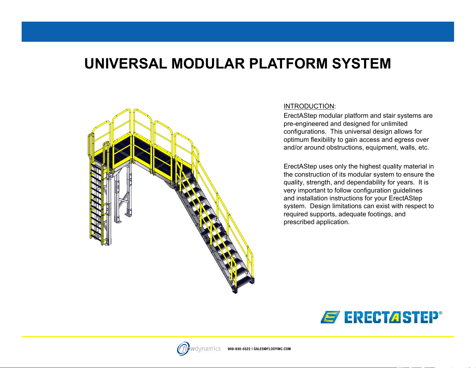
ErectAStep modular platform and stair systems are
pre-engineered and designed for unlimited
configurations. This universal design allows for
optimum flexibility to gain access and egress over
and/or around obstructions, equipment, walls, etc.
ErectAStep uses only the highest quality material in
the construction of its modular system to ensure the
quality, strength, and dependability for years. It is
very important to follow configuration guidelines
and installation instructions for your ErectAStep
system. Design limitations can exist with respect to
required supports, adequate footings, and
prescribed application.
34-29-16
Page 5
COMPONENTS
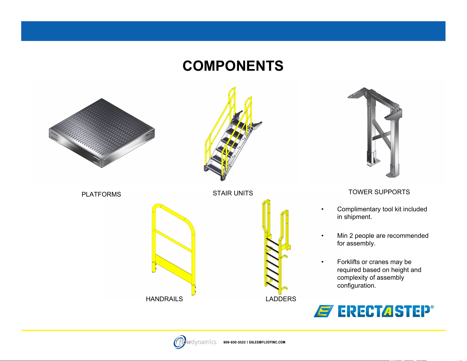
PLATFORMS
HANDRAILS
STAIR UNITS
TOWER SUPPORTS
• Complimentary tool kit included
in shipment.
• Min 2 people are recommended
for assembly.
• Forklifts or cranes may be
required based on height and
complexity of assembly
configuration.
LADDERS
44-29-16
Page 6
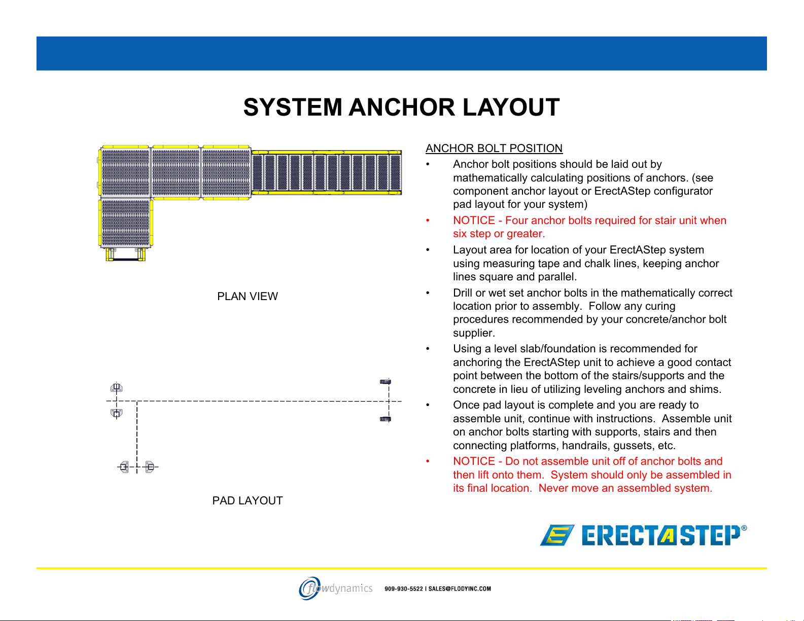
SYSTEM ANCHOR LAYOUT
PLAN VIEW
PAD LAYOUT
ANCHOR BOLT POSITION
• Anchor bolt positions should be laid out by
mathematically calculating positions of anchors. (see
component anchor layout or ErectAStep configurator
pad layout for your system)
• NOTICE - Four anchor bolts required for stair unit when
six step or greater.
• Layout area for location of your ErectAStep system
using measuring tape and chalk lines, keeping anchor
lines square and parallel.
• Drill or wet set anchor bolts in the mathematically correct
location prior to assembly. Follow any curing
procedures recommended by your concrete/anchor bolt
supplier.
• Using a level slab/foundation is recommended for
anchoring the ErectAStep unit to achieve a good contact
point between the bottom of the stairs/supports and the
concrete in lieu of utilizing leveling anchors and shims.
• Once pad layout is complete and you are ready to
assemble unit, continue with instructions. Assemble unit
on anchor bolts starting with supports, stairs and then
connecting platforms, handrails, gussets, etc.
• NOTICE - Do not assemble unit off of anchor bolts and
then lift onto them. System should only be assembled in
its final location. Never move an assembled system.
54-29-16
Page 7
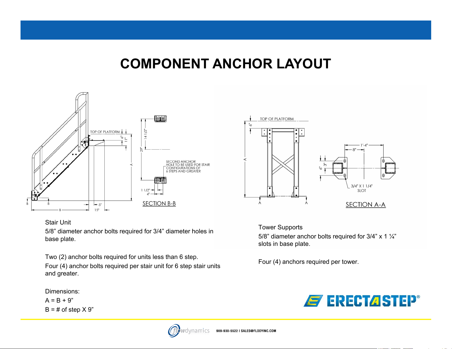
COMPONENT ANCHOR LAYOUT
Stair Unit
5/8” diameter anchor bolts required for 3/4” diameter holes in
base plate.
Two (2) anchor bolts required for units less than 6 step.
Four (4) anchor bolts required per stair unit for 6 step stair units
and greater.
Dimensions:
A = B + 9”
B = # of step X 9”
4-29-16
Tower Supports
5/8” diameter anchor bolts required for 3/4” x 1 ¼”
slots in base plate.
Four (4) anchors required per tower.
6
Page 8
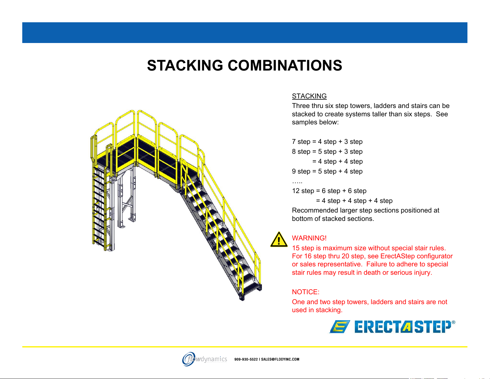
STACKING COMBINATIONS
STACKING
Three thru six step towers, ladders and stairs can be
stacked to create systems taller than six steps. See
samples below:
7 step = 4 step + 3 step
8 step = 5 step + 3 step
= 4 step + 4 step
9 step = 5 step + 4 step
…..
12 step = 6 step + 6 step
= 4 step + 4 step + 4 step
Recommended larger step sections positioned at
bottom of stacked sections.
WARNING!
15 step is maximum size without special stair rules.
For 16 step thru 20 step, see ErectAStep configurator
or sales representative. Failure to adhere to special
stair rules may result in death or serious injury.
4-29-16
NOTICE:
One and two step towers, ladders and stairs are not
used in stacking.
7
Page 9
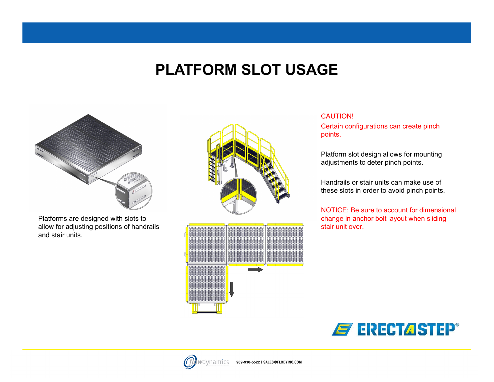
PLATFORM SLOT USAGE
Platforms are designed with slots to
allow for adjusting positions of handrails
and stair units.
CAUTION!
Certain configurations can create pinch
points.
Platform slot design allows for mounting
adjustments to deter pinch points.
Handrails or stair units can make use of
these slots in order to avoid pinch points.
NOTICE: Be sure to account for dimensional
change in anchor bolt layout when sliding
stair unit over.
84-29-16
Page 10
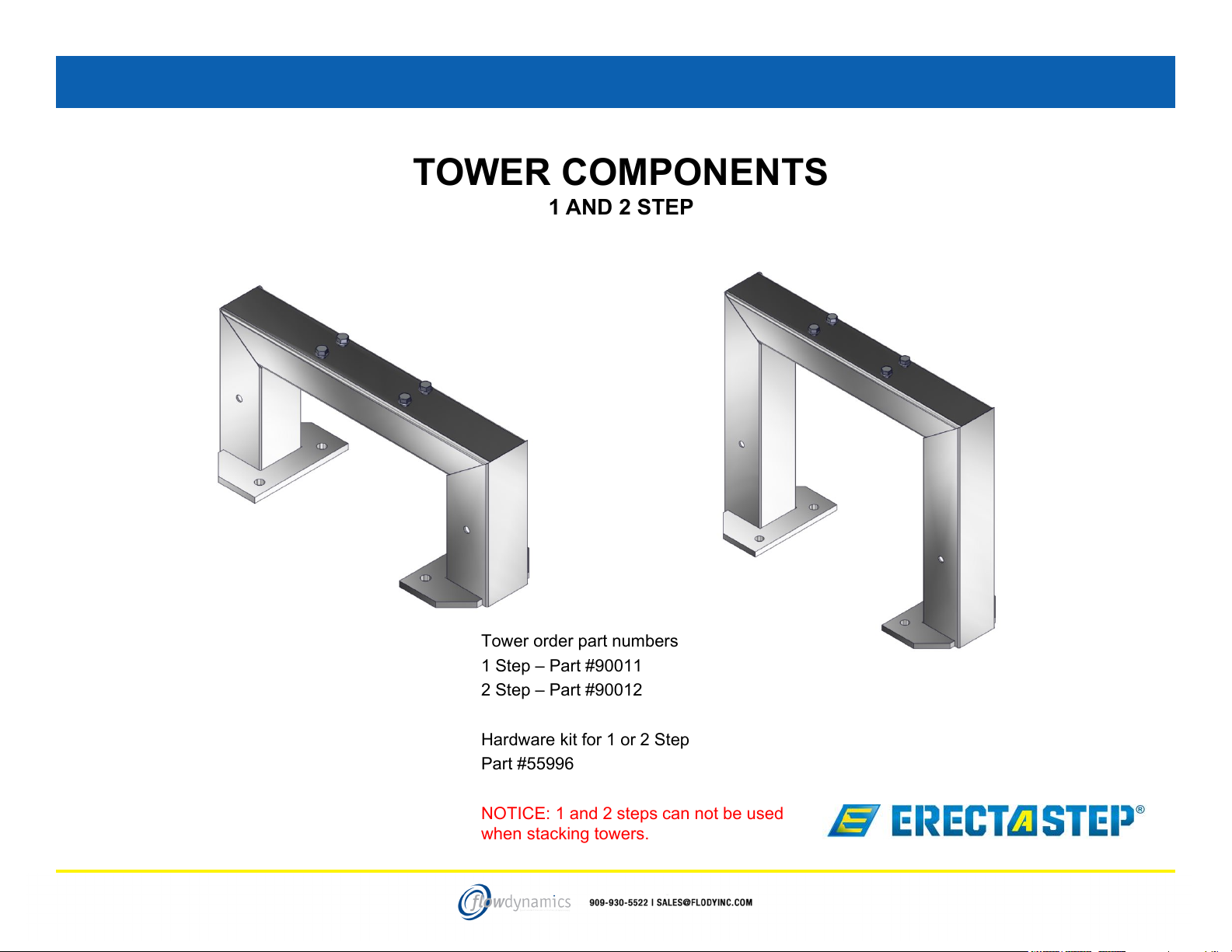
TOWER COMPONENTS
1 AND 2 STEP
Tower order part numbers
1 Step – Part #90011
2 Step – Part #90012
Hardware kit for 1 or 2 Step
Part #55996
NOTICE: 1 and 2 steps can not be used
when stacking towers.
94-29-16
Page 11
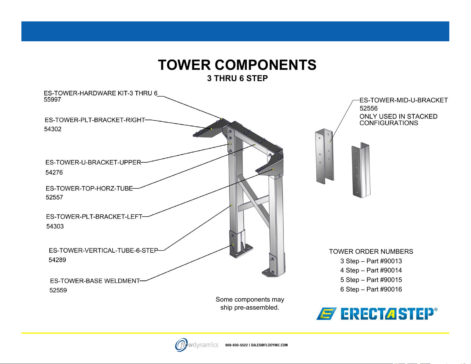
TOWER COMPONENTS
3 THRU 6 STEP
Some components may
ship pre-assembled.
TOWER ORDER NUMBERS
3 Step – Part #90013
4 Step – Part #90014
5 Step – Part #90015
6 Step – Part #90016
104-29-16
Page 12
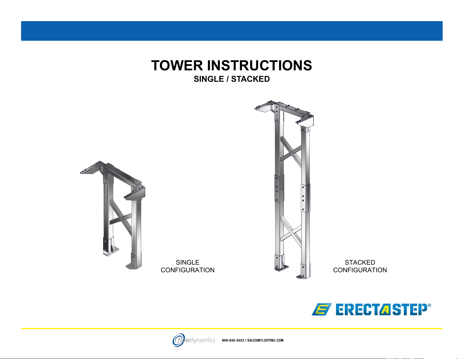
TOWER INSTRUCTIONS
SINGLE / STACKED
SINGLE
CONFIGURATION
STACKED
CONFIGURATION
114-29-16
Page 13
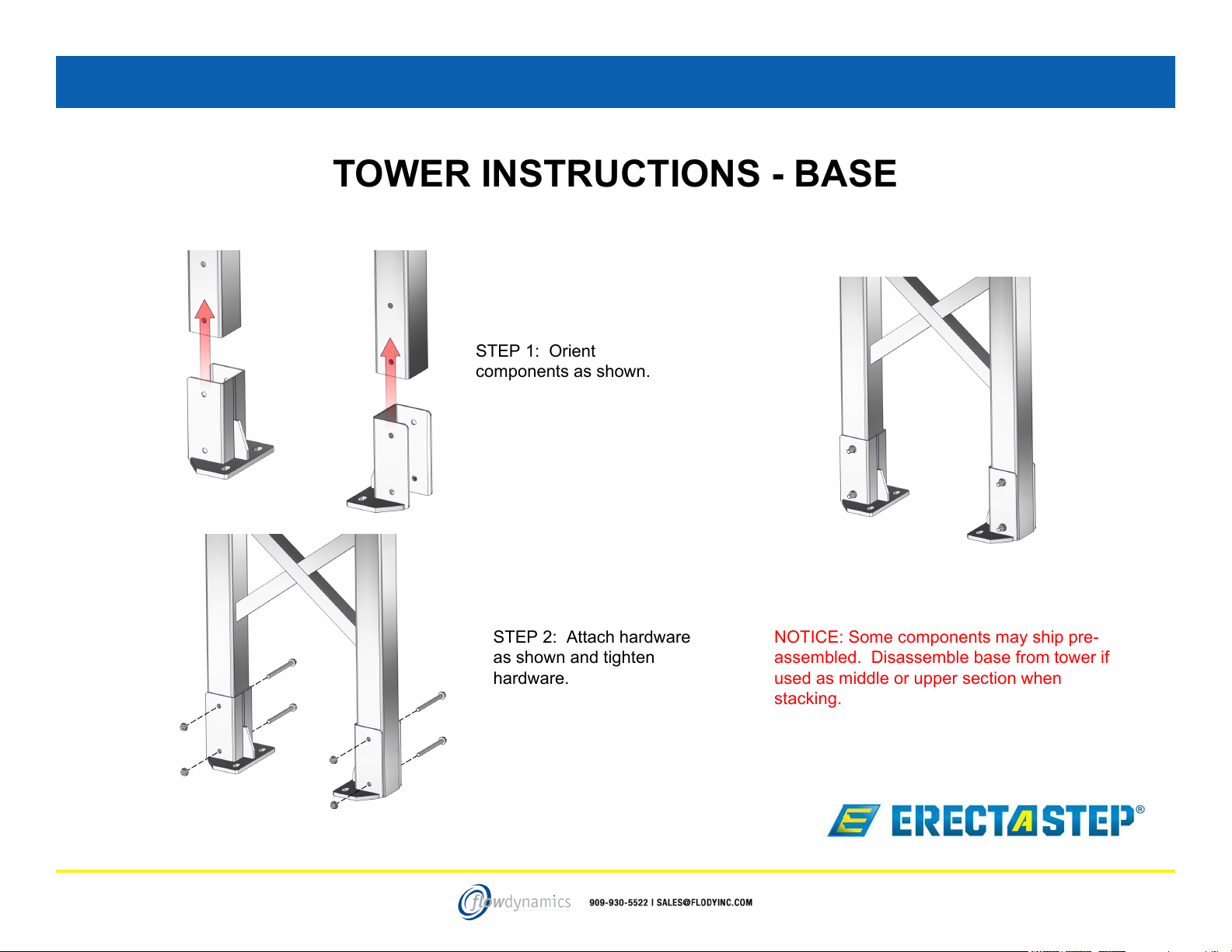
TOWER INSTRUCTIONS - BASE
STEP 1: Orient
components as shown.
STEP 2: Attach hardware
as shown and tighten
hardware.
NOTICE: Some components may ship pre-
assembled. Disassemble base from tower if
used as middle or upper section when
stacking.
124-29-16
Page 14
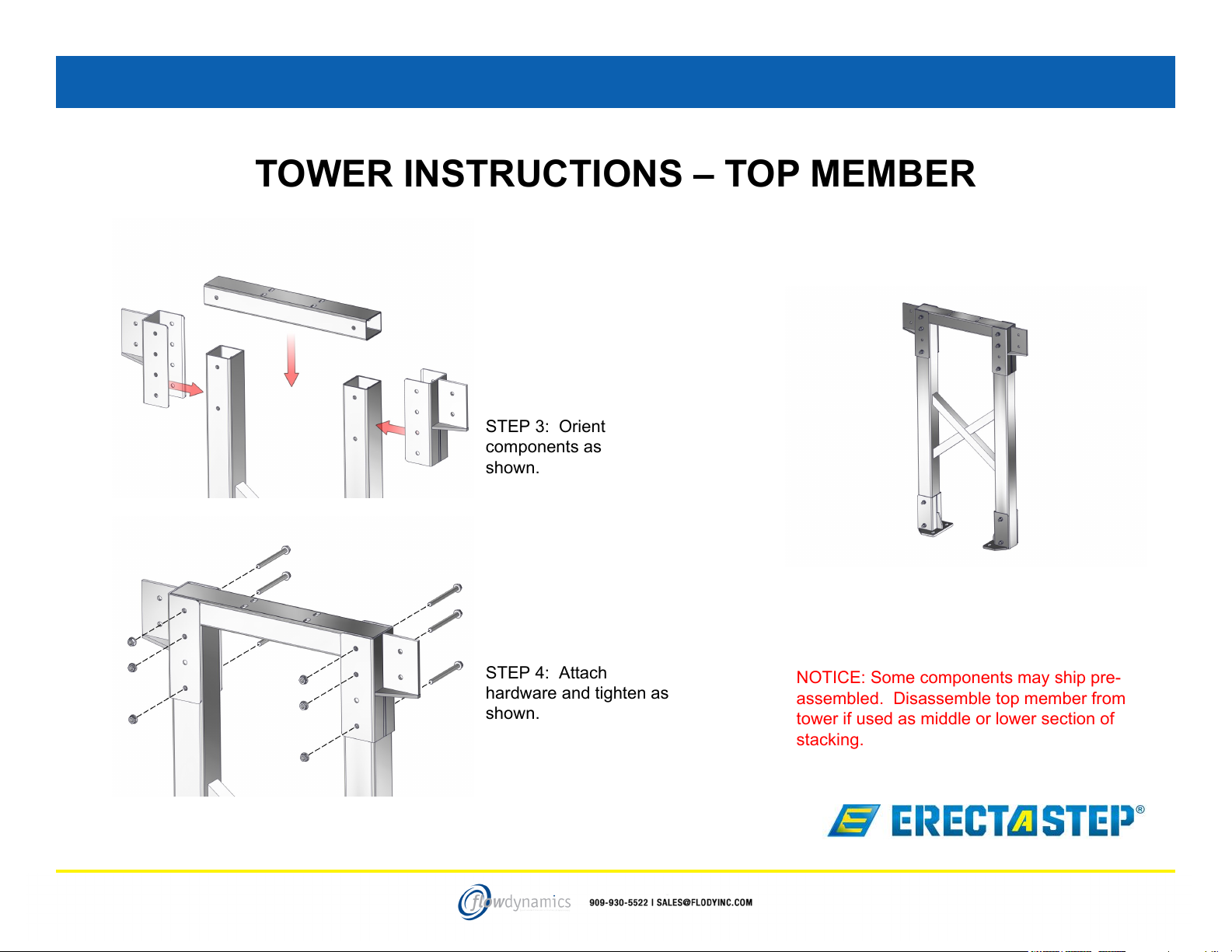
TOWER INSTRUCTIONS – TOP MEMBER
STEP 3: Orient
components as
shown.
STEP 4: Attach
hardware and tighten as
shown.
NOTICE: Some components may ship pre-
assembled. Disassemble top member from
tower if used as middle or lower section of
stacking.
134-29-16
Page 15
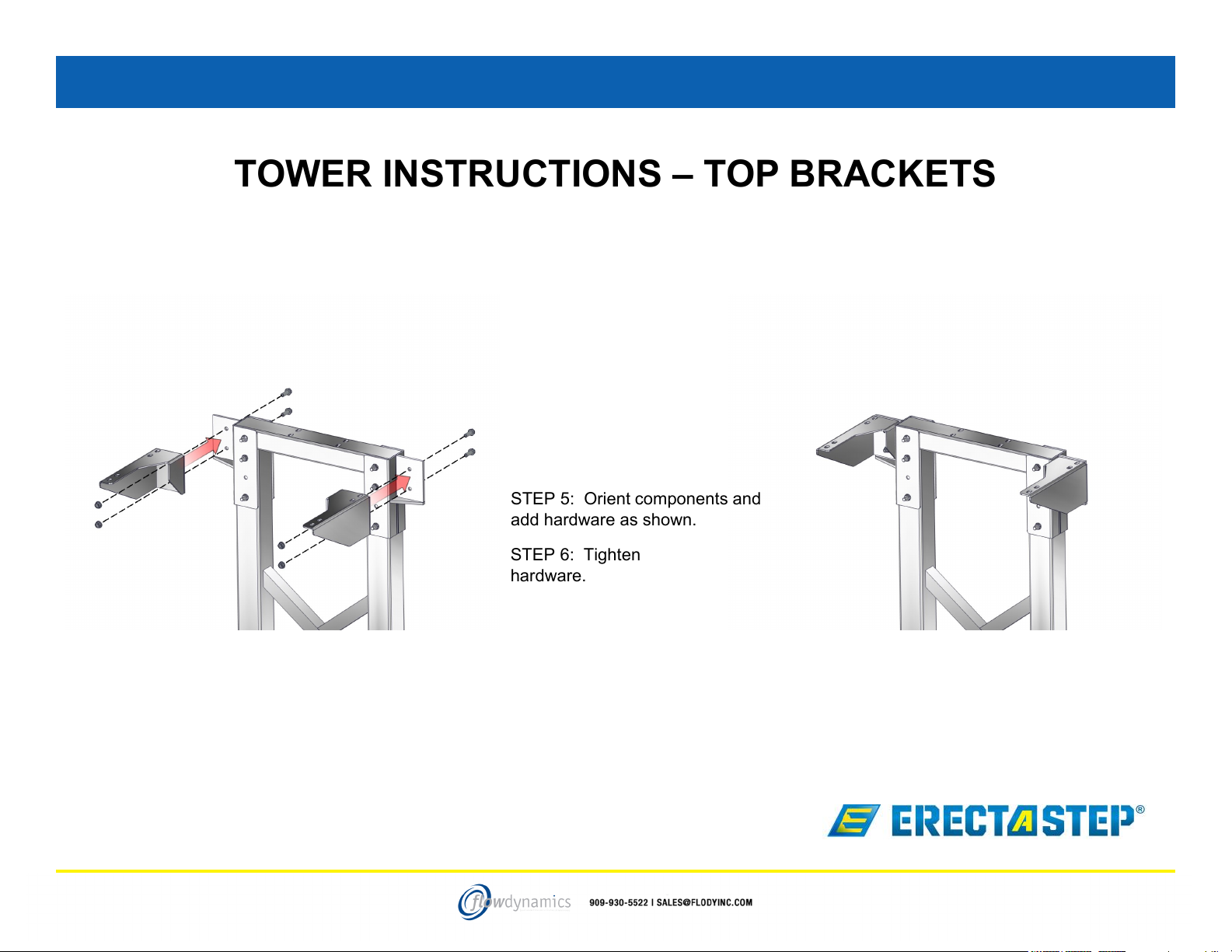
TOWER INSTRUCTIONS – TOP BRACKETS
STEP 5: Orient components and
add hardware as shown.
STEP 6: Tighten
hardware.
144-29-16
Page 16
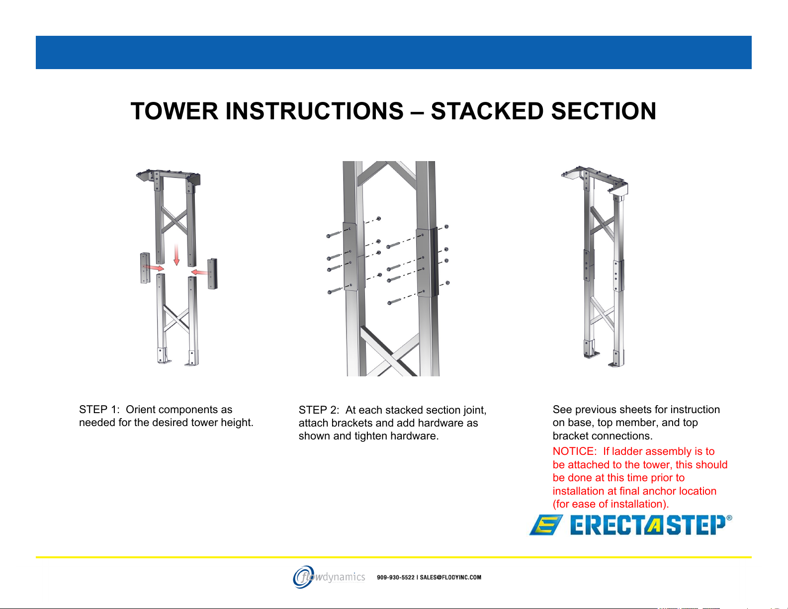
TOWER INSTRUCTIONS – STACKED SECTION
STEP 1: Orient components as
needed for the desired tower height.
STEP 2: At each stacked section joint,
attach brackets and add hardware as
shown and tighten hardware.
See previous sheets for instruction
on base, top member, and top
bracket connections.
NOTICE: If ladder assembly is to
be attached to the tower, this should
be done at this time prior to
installation at final anchor location
(for ease of installation).
154-29-16
Page 17
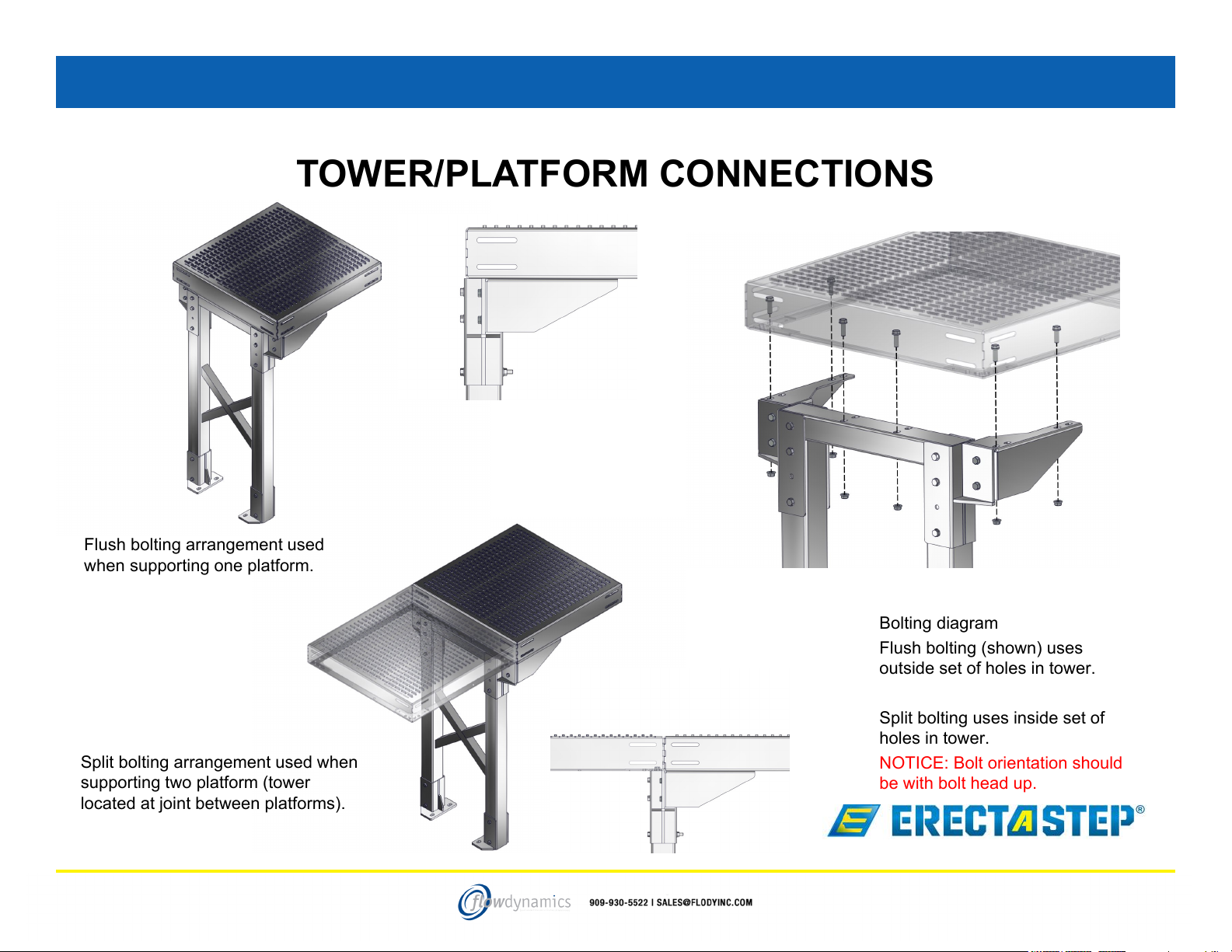
TOWER/PLATFORM CONNECTIONS
Flush bolting arrangement used
when supporting one platform.
Bolting diagram
Flush bolting (shown) uses
outside set of holes in tower.
Split bolting arrangement used when
supporting two platform (tower
located at joint between platforms).
Split bolting uses inside set of
holes in tower.
NOTICE: Bolt orientation should
be with bolt head up.
164-29-16
Page 18
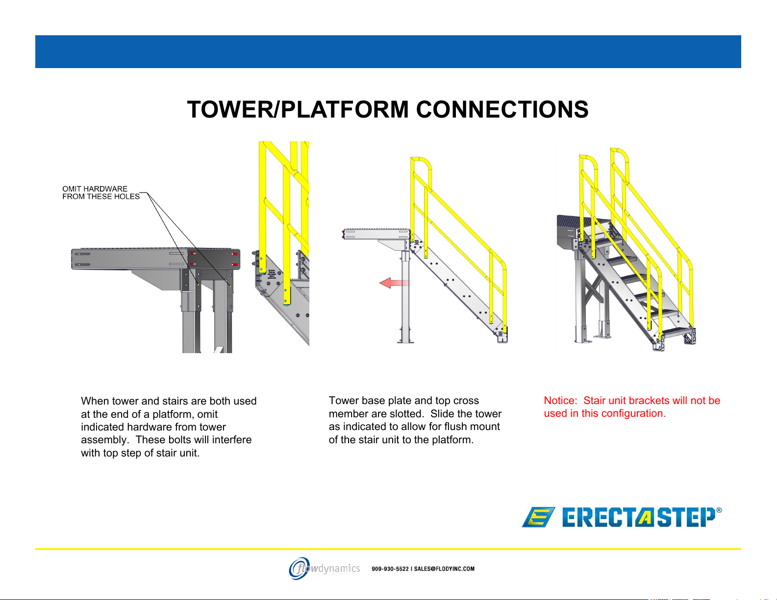
TOWER/PLATFORM CONNECTIONS
When tower and stairs are both used
at the end of a platform, omit
indicated hardware from tower
assembly. These bolts will interfere
with top step of stair unit.
Tower base plate and top cross
member are slotted. Slide the tower
as indicated to allow for flush mount
of the stair unit to the platform.
Notice: Stair unit brackets will not be
used in this configuration.
174-29-16
Page 19
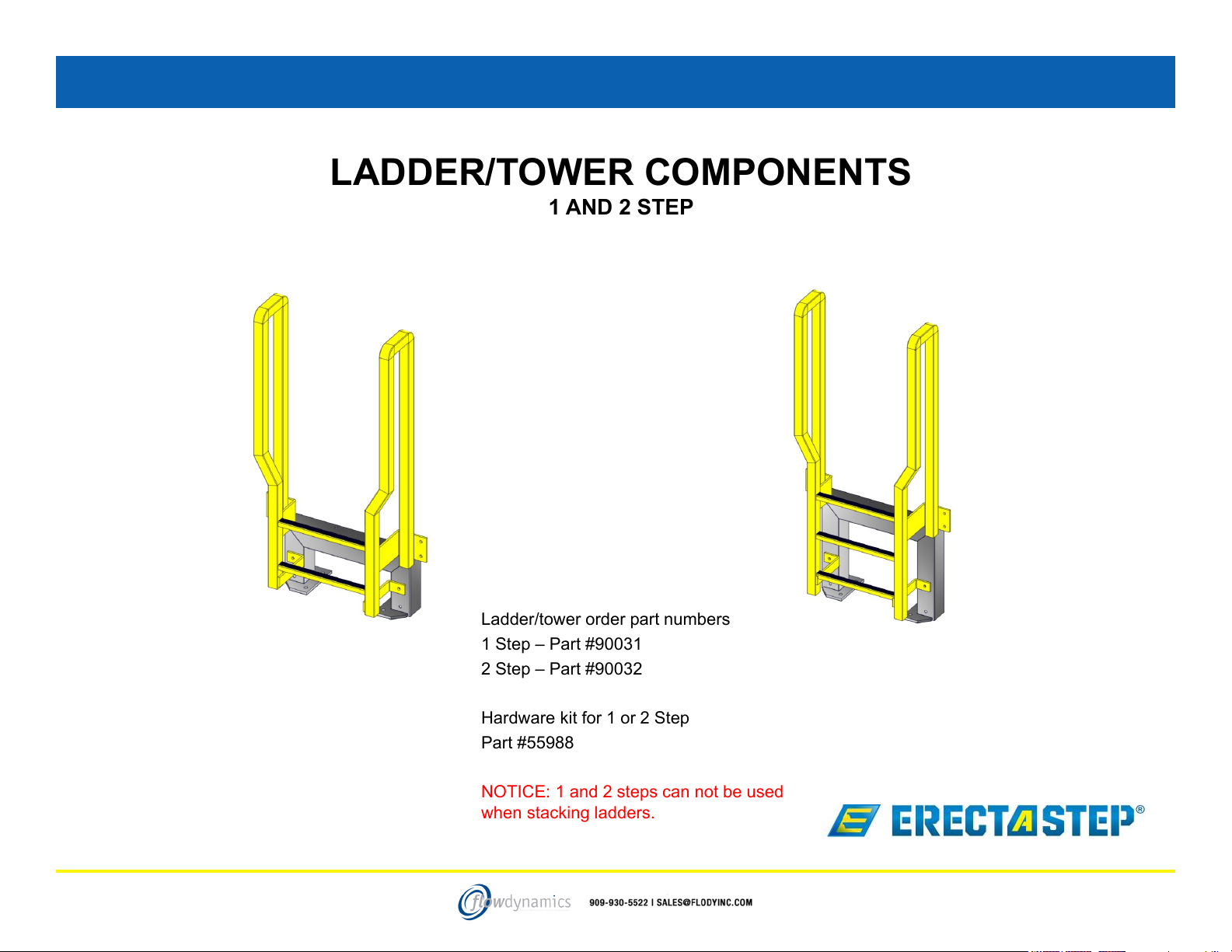
LADDER/TOWER COMPONENTS
1 AND 2 STEP
Ladder/tower order part numbers
1 Step – Part #90031
2 Step – Part #90032
Hardware kit for 1 or 2 Step
Part #55988
NOTICE: 1 and 2 steps can not be used
when stacking ladders.
184-29-16
Page 20
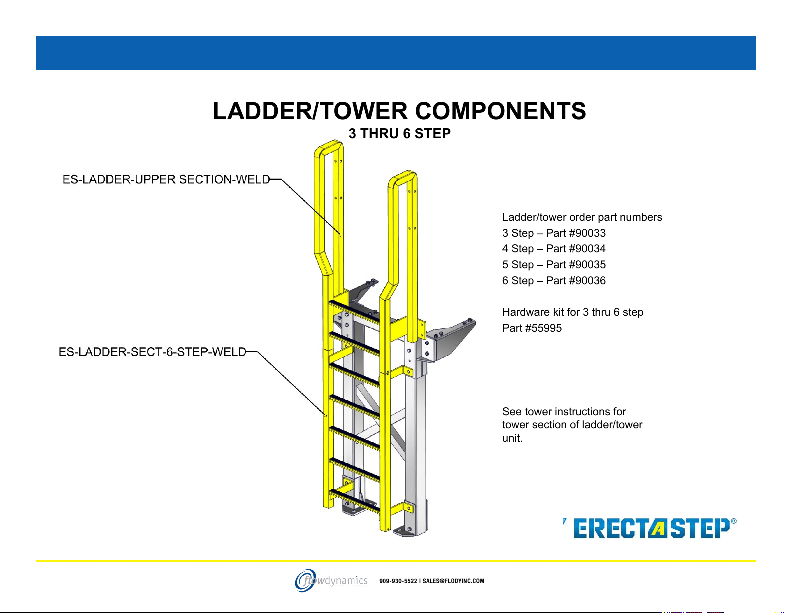
LADDER/TOWER COMPONENTS
3 THRU 6 STEP
Ladder/tower order part numbers
3 Step – Part #90033
4 Step – Part #90034
5 Step – Part #90035
6 Step – Part #90036
Hardware kit for 3 thru 6 step
Part #55995
See tower instructions for
tower section of ladder/tower
unit.
194-29-16
Page 21
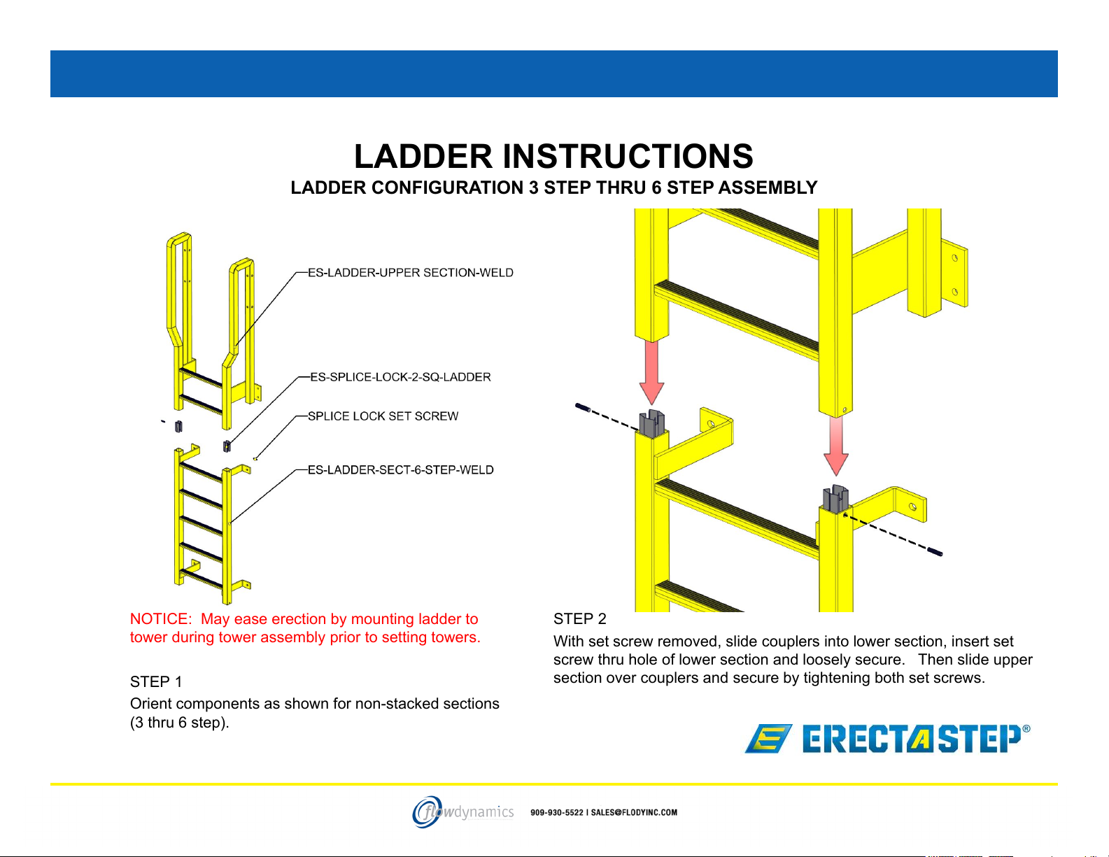
LADDER INSTRUCTIONS
LADDER CONFIGURATION 3 STEP THRU 6 STEP ASSEMBLY
NOTICE: May ease erection by mounting ladder to
tower during tower assembly prior to setting towers.
STEP 1
Orient components as shown for non-stacked sections
(3 thru 6 step).
STEP 2
With set screw removed, slide couplers into lower section, insert set
screw thru hole of lower section and loosely secure. Then slide upper
section over couplers and secure by tightening both set screws.
204-29-16
Page 22
LADDER/TOWER INSTRUCTIONS
LADDER CONFIGURATION 3 STEP THRU 6 STEP ASSEMBLY
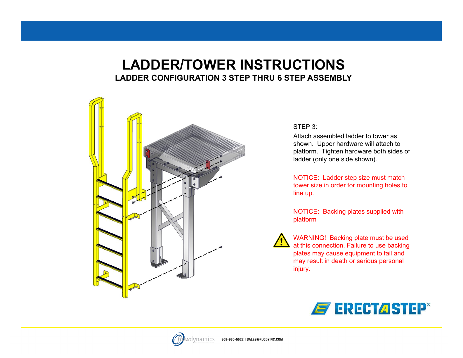
STEP 3:
Attach assembled ladder to tower as
shown. Upper hardware will attach to
platform. Tighten hardware both sides of
ladder (only one side shown).
NOTICE: Ladder step size must match
tower size in order for mounting holes to
line up.
NOTICE: Backing plates supplied with
platform
4-29-16
WARNING! Backing plate must be used
at this connection. Failure to use backing
plates may cause equipment to fail and
may result in death or serious personal
injury.
21
Page 23
LADDER INSTRUCTIONS
LADDER CONFIGURATION STACKED ASSEMBLIES (GREATER THAN 6 STEP)
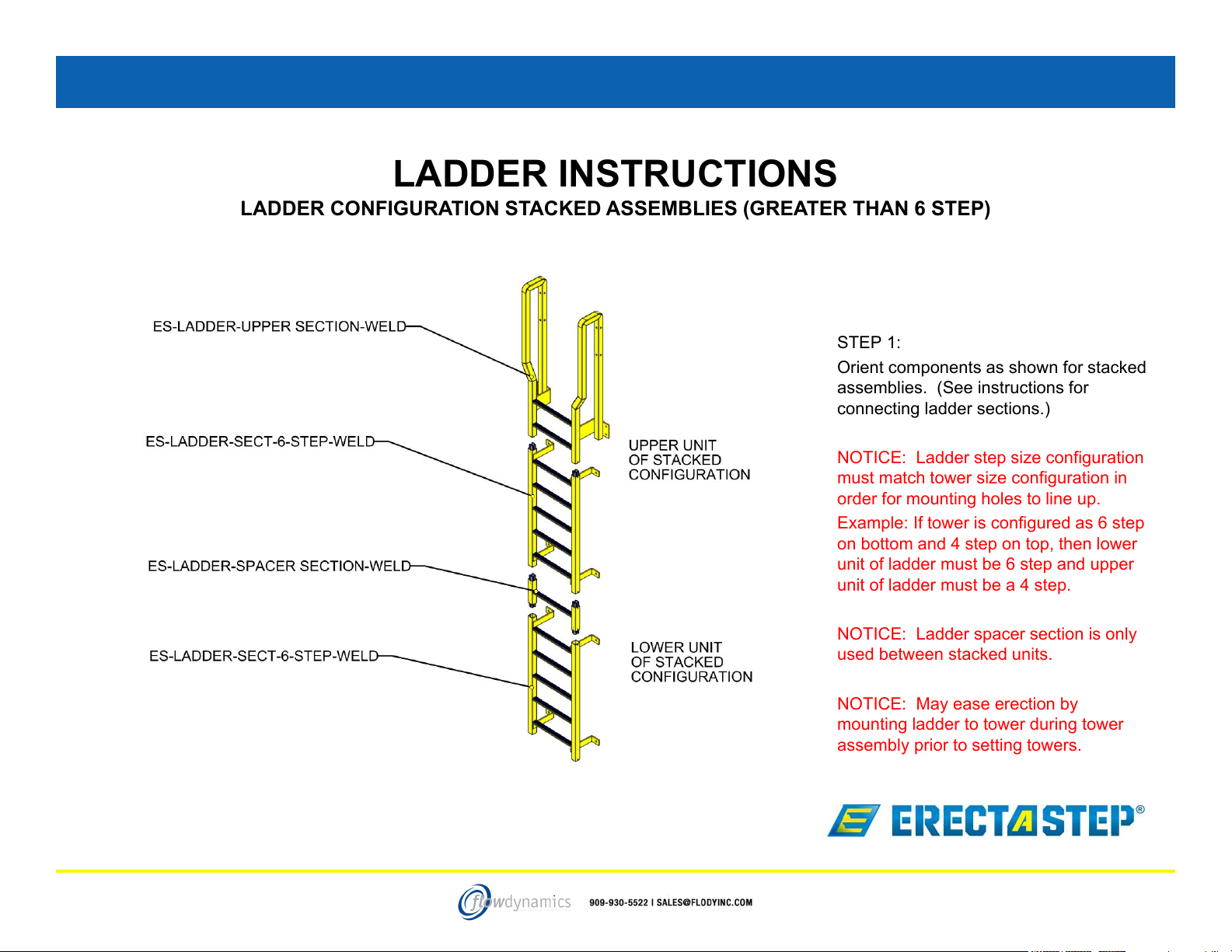
STEP 1:
Orient components as shown for stacked
assemblies. (See instructions for
connecting ladder sections.)
NOTICE: Ladder step size configuration
must match tower size configuration in
order for mounting holes to line up.
Example: If tower is configured as 6 step
on bottom and 4 step on top, then lower
unit of ladder must be 6 step and upper
unit of ladder must be a 4 step.
NOTICE: Ladder spacer section is only
used between stacked units.
NOTICE: May ease erection by
mounting ladder to tower during tower
assembly prior to setting towers.
224-29-16
Page 24
LADDER INSTRUCTIONS
LADDER CONFIGURATION STACKED ASSEMBLIES (GREATER THAN 6 STEP)
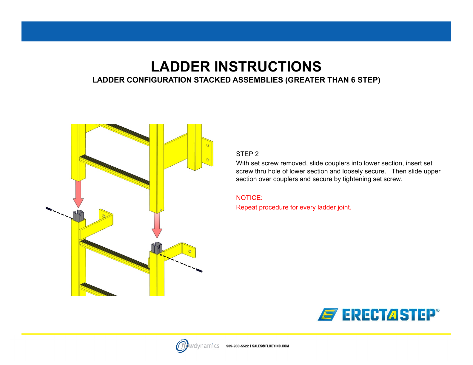
STEP 2
With set screw removed, slide couplers into lower section, insert set
screw thru hole of lower section and loosely secure. Then slide upper
section over couplers and secure by tightening set screw.
NOTICE:
Repeat procedure for every ladder joint.
234-29-16
Page 25
LADDER/TOWER INSTRUCTIONS
LADDER CONFIGURATION STACKED ASSEMBLIES (GREATER THAN 6 STEP)
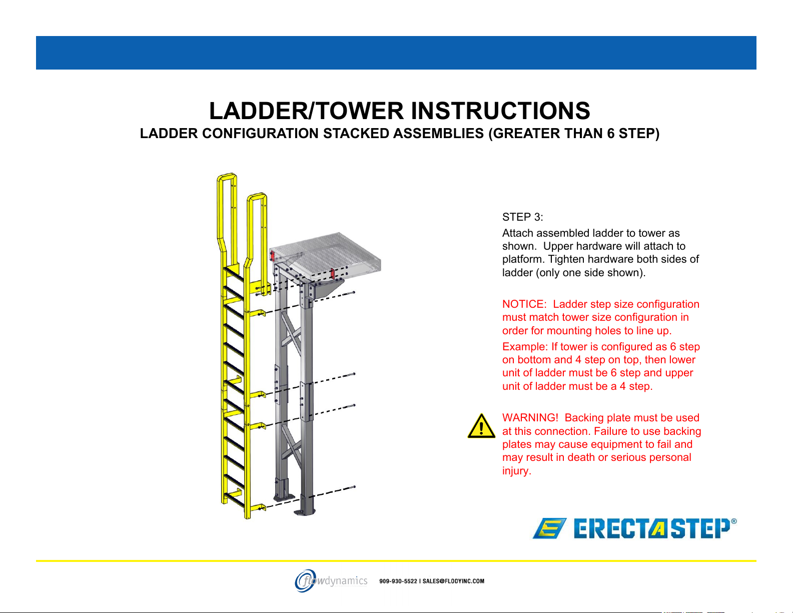
STEP 3:
Attach assembled ladder to tower as
shown. Upper hardware will attach to
platform. Tighten hardware both sides of
ladder (only one side shown).
NOTICE: Ladder step size configuration
must match tower size configuration in
order for mounting holes to line up.
Example: If tower is configured as 6 step
on bottom and 4 step on top, then lower
unit of ladder must be 6 step and upper
unit of ladder must be a 4 step.
4-29-16
WARNING! Backing plate must be used
at this connection. Failure to use backing
plates may cause equipment to fail and
may result in death or serious personal
injury.
24
Page 26
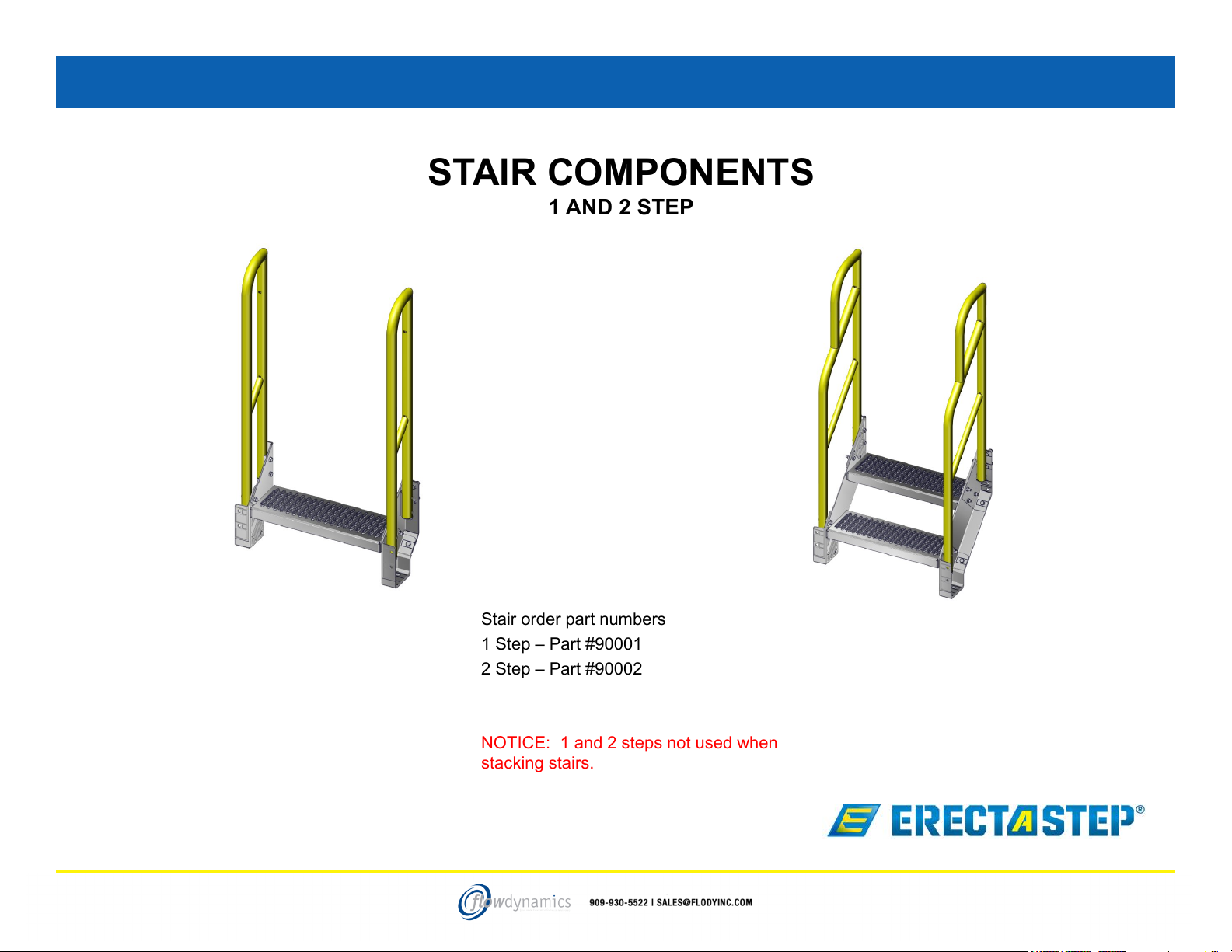
STAIR COMPONENTS
1 AND 2 STEP
Stair order part numbers
1 Step – Part #90001
2 Step – Part #90002
NOTICE: 1 and 2 steps not used when
stacking stairs.
254-29-16
Page 27
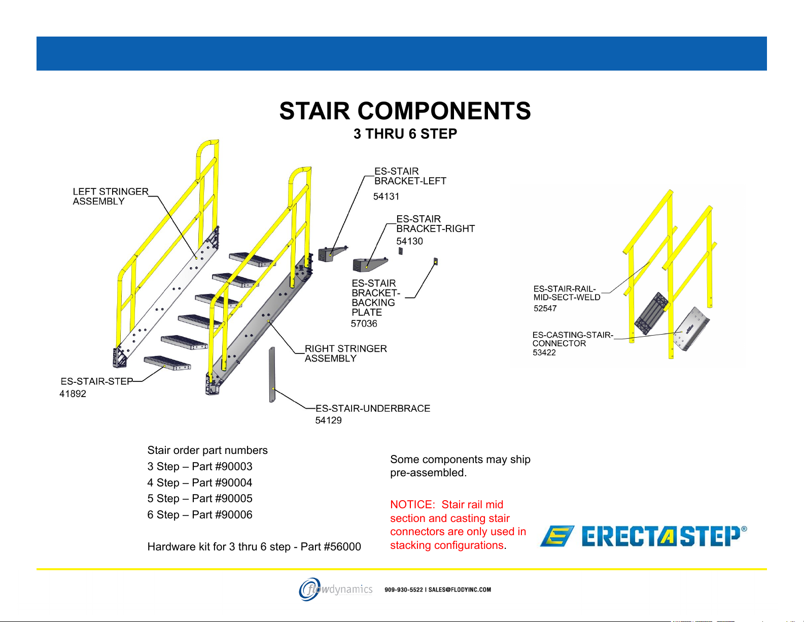
STAIR COMPONENTS
3 THRU 6 STEP
Stair order part numbers
3 Step – Part #90003
4 Step – Part #90004
5 Step – Part #90005
6 Step – Part #90006
Hardware kit for 3 thru 6 step - Part #56000
Some components may ship
pre-assembled.
NOTICE: Stair rail mid
section and casting stair
connectors are only used in
stacking configurations.
264-29-16
Page 28
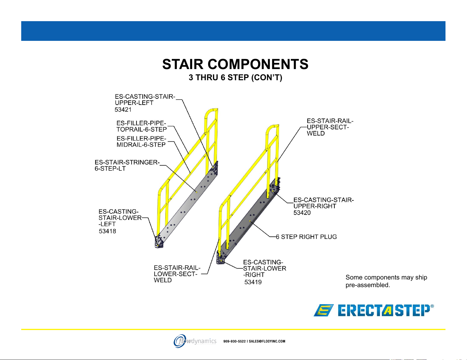
STAIR COMPONENTS
3 THRU 6 STEP (CON’T)
Some components may ship
pre-assembled.
274-29-16
Page 29
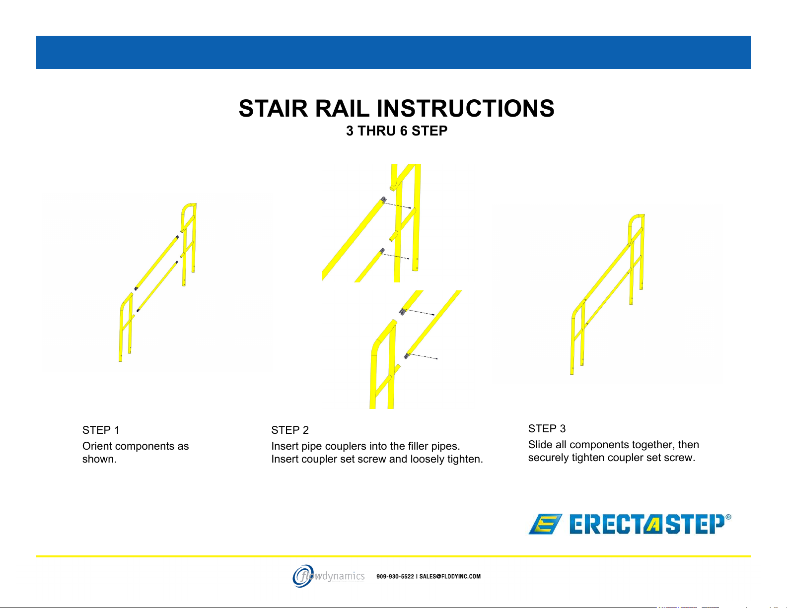
STAIR RAIL INSTRUCTIONS
3 THRU 6 STEP
STEP 1
Orient components as
shown.
STEP 2
Insert pipe couplers into the filler pipes.
Insert coupler set screw and loosely tighten.
STEP 3
Slide all components together, then
securely tighten coupler set screw.
284-29-16
Page 30
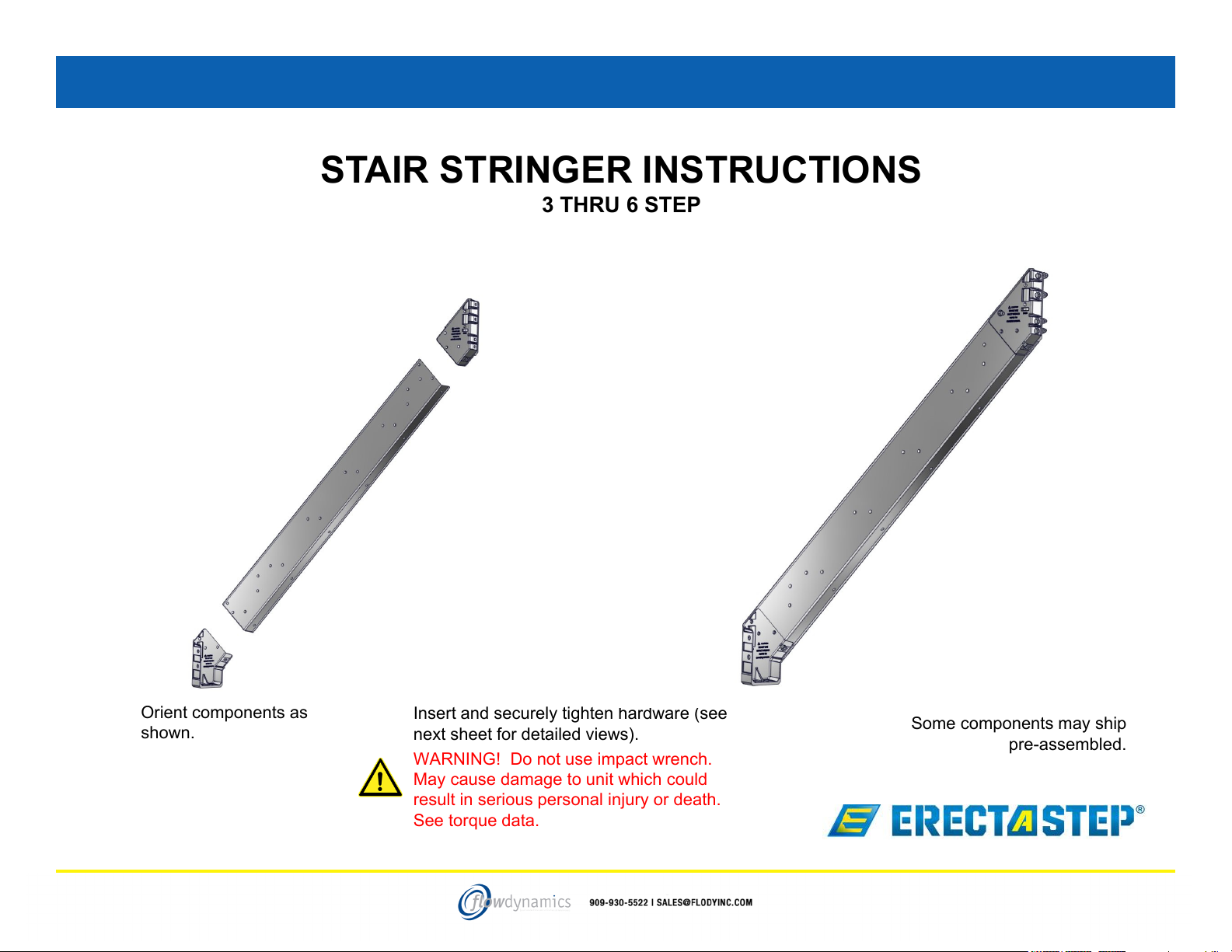
STAIR STRINGER INSTRUCTIONS
3 THRU 6 STEP
4-29-16
STEP 1
Orient components as
shown.
STEP 2
Insert and securely tighten hardware (see
next sheet for detailed views).
WARNING! Do not use impact wrench.
May cause damage to unit which could
result in serious personal injury or death.
See torque data.
Some components may ship
pre-assembled.
29
Page 31
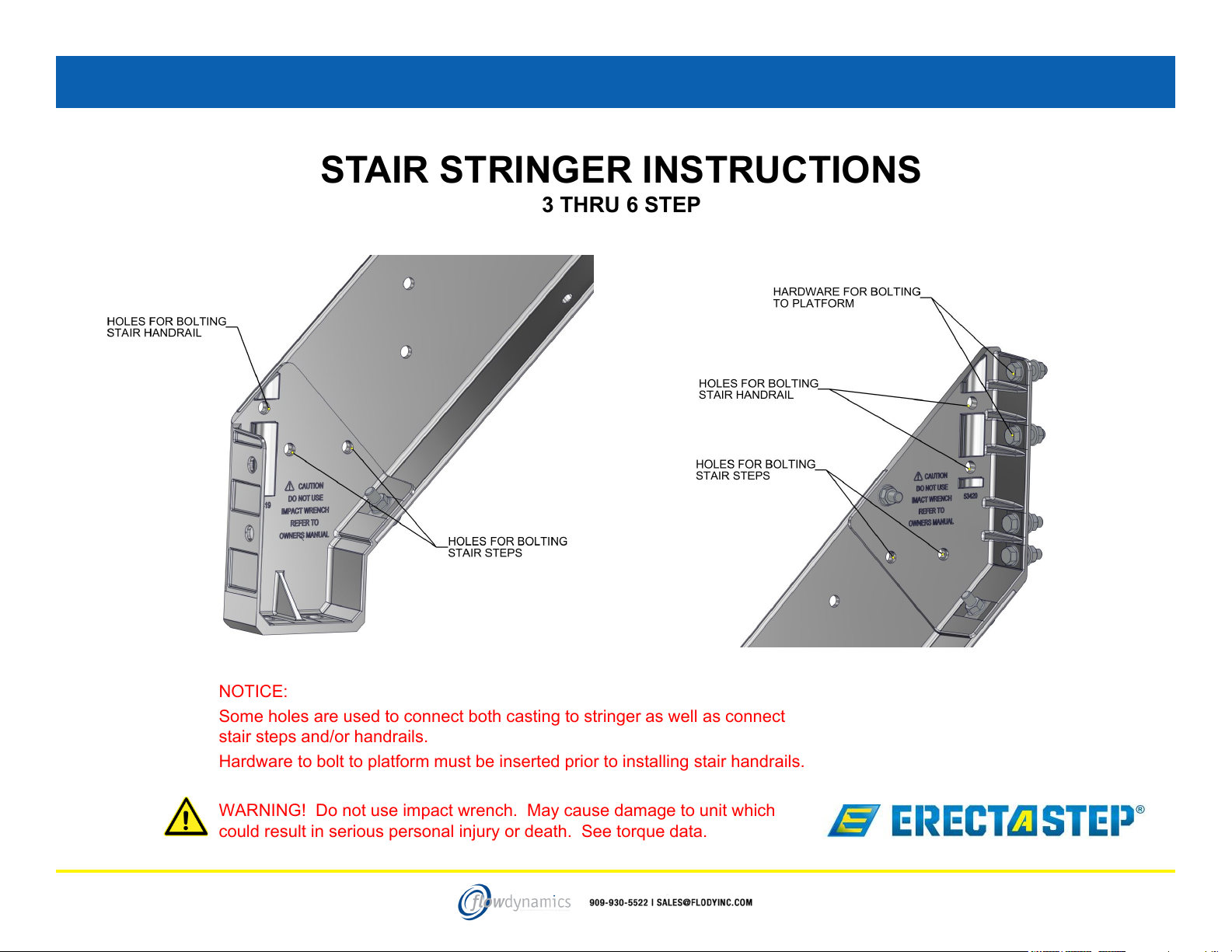
STAIR STRINGER INSTRUCTIONS
3 THRU 6 STEP
4-29-16
NOTICE:
Some holes are used to connect both casting to stringer as well as connect
stair steps and/or handrails.
Hardware to bolt to platform must be inserted prior to installing stair handrails.
WARNING! Do not use impact wrench. May cause damage to unit which
could result in serious personal injury or death. See torque data.
30
Page 32
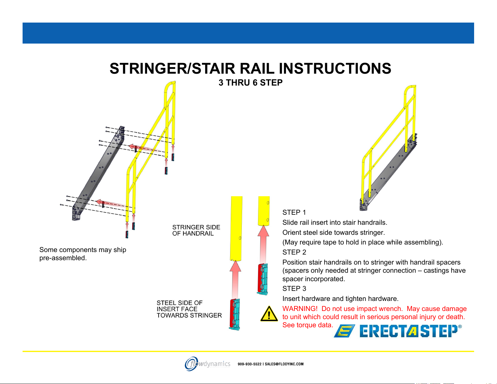
STRINGER/STAIR RAIL INSTRUCTIONS
Some components may ship
pre-assembled.
3 THRU 6 STEP
STEP 1
Slide rail insert into stair handrails.
Orient steel side towards stringer.
(May require tape to hold in place while assembling).
STEP 2
Position stair handrails on to stringer with handrail spacers
(spacers only needed at stringer connection – castings have
spacer incorporated.
STEP 3
Insert hardware and tighten hardware.
WARNING! Do not use impact wrench. May cause damage
to unit which could result in serious personal injury or death.
See torque data.
4-29-16
31
Page 33
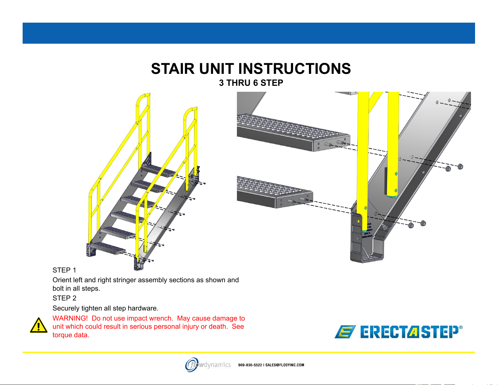
STAIR UNIT INSTRUCTIONS
3 THRU 6 STEP
STEP 1
Orient left and right stringer assembly sections as shown and
bolt in all steps.
STEP 2
Securely tighten all step hardware.
WARNING! Do not use impact wrench. May cause damage to
unit which could result in serious personal injury or death. See
torque data.
4-29-16
32
Page 34
STAIR UNIT INSTRUCTIONS
3 THRU 6 STEP
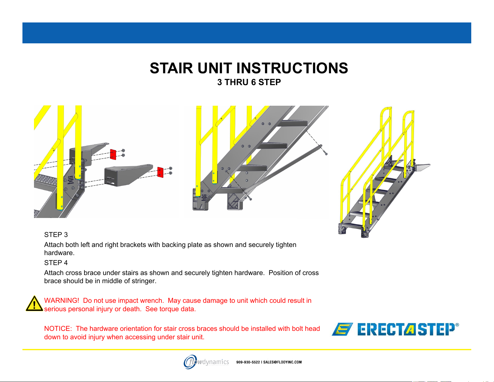
STEP 3
Attach both left and right brackets with backing plate as shown and securely tighten
hardware.
STEP 4
Attach cross brace under stairs as shown and securely tighten hardware. Position of cross
brace should be in middle of stringer.
WARNING! Do not use impact wrench. May cause damage to unit which could result in
serious personal injury or death. See torque data.
NOTICE: The hardware orientation for stair cross braces should be installed with bolt head
down to avoid injury when accessing under stair unit.
4-29-16
33
Page 35
STAIR UNIT INSTRUCTIONS
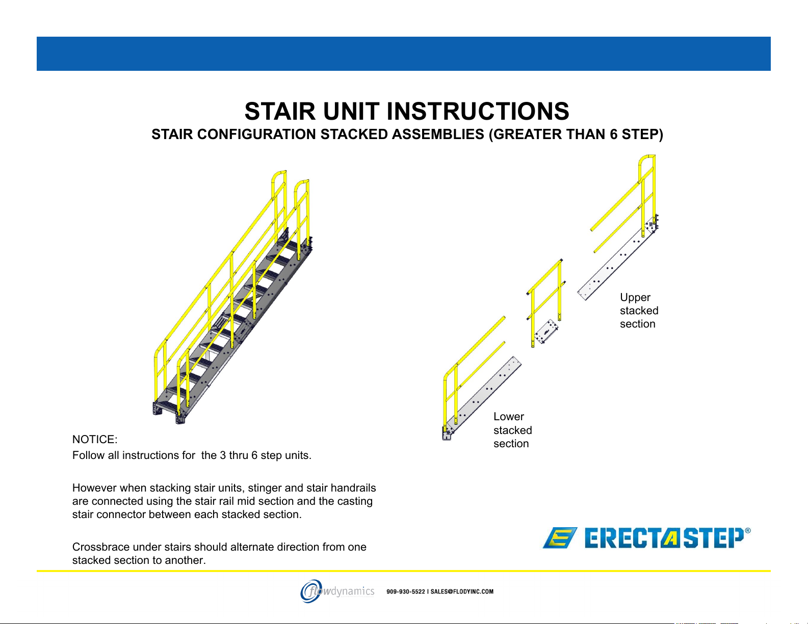
STAIR CONFIGURATION STACKED ASSEMBLIES (GREATER THAN 6 STEP)
Upper
stacked
section
NOTICE:
Follow all instructions for the 3 thru 6 step units.
However when stacking stair units, stinger and stair handrails
are connected using the stair rail mid section and the casting
stair connector between each stacked section.
Crossbrace under stairs should alternate direction from one
stacked section to another.
4-29-16
Lower
stacked
section
34
Page 36
PLATFORM COMPONENTS
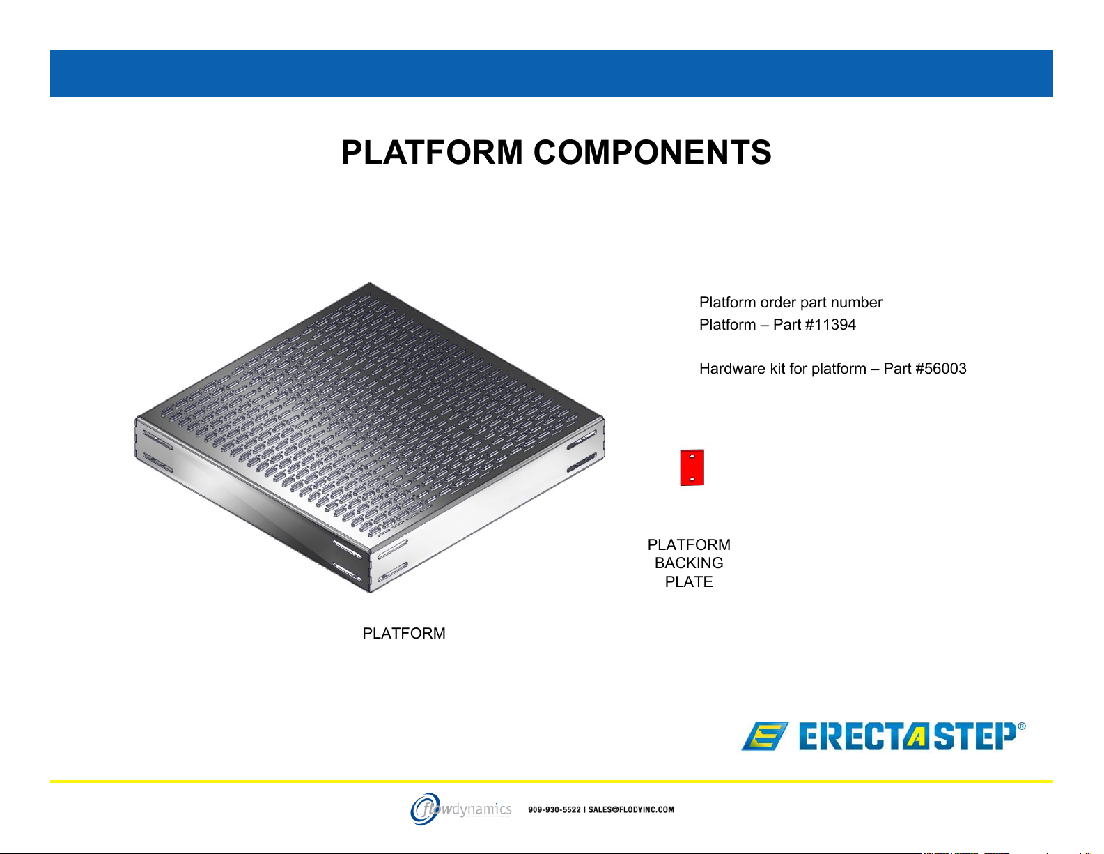
Platform order part number
Platform – Part #11394
Hardware kit for platform – Part #56003
PLATFORM
BACKING
PLATE
4-29-16
PLATFORM
35
Page 37
PLATFORM CONNECTIONS
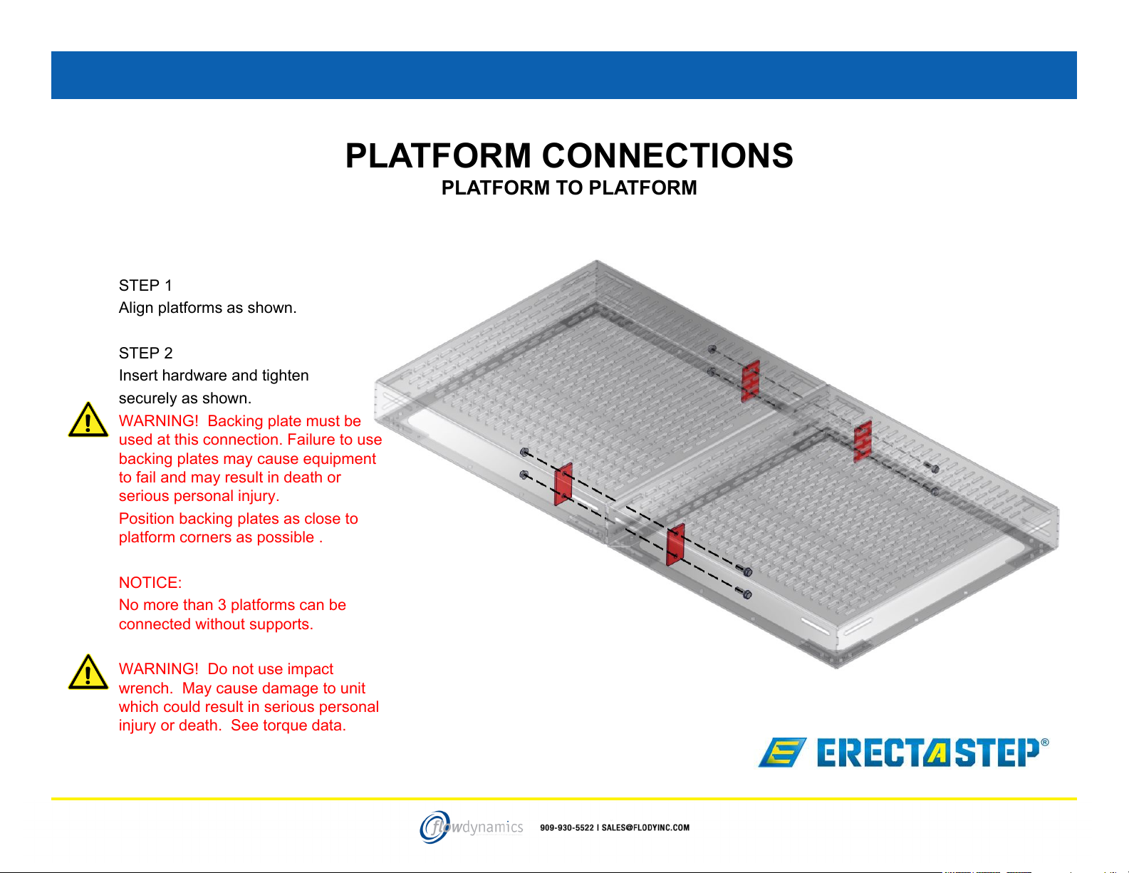
STEP 1
Align platforms as shown.
STEP 2
Insert hardware and tighten
securely as shown.
WARNING! Backing plate must be
used at this connection. Failure to use
backing plates may cause equipment
to fail and may result in death or
serious personal injury.
Position backing plates as close to
platform corners as possible .
PLATFORM TO PLATFORM
NOTICE:
No more than 3 platforms can be
connected without supports.
WARNING! Do not use impact
wrench. May cause damage to unit
which could result in serious personal
injury or death. See torque data.
4-29-16
36
Page 38
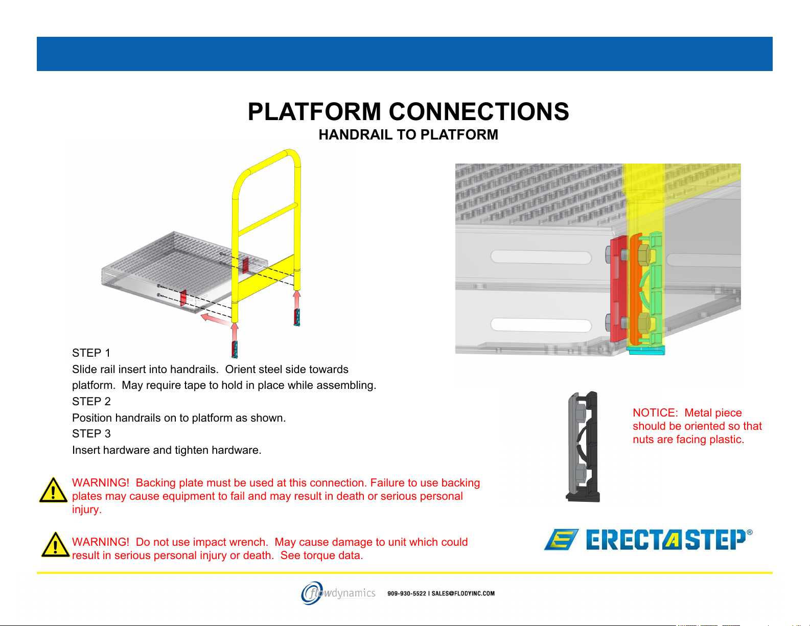
PLATFORM CONNECTIONS
HANDRAIL TO PLATFORM
STEP 1
Slide rail insert into handrails. Orient steel side towards
platform. May require tape to hold in place while assembling.
STEP 2
Position handrails on to platform as shown.
STEP 3
Insert hardware and tighten hardware.
NOTICE: Metal piece
should be oriented so that
nuts are facing plastic.
WARNING! Backing plate must be used at this connection. Failure to use backing
plates may cause equipment to fail and may result in death or serious personal
injury.
WARNING! Do not use impact wrench. May cause damage to unit which could
result in serious personal injury or death. See torque data.
4-29-16
37
Page 39
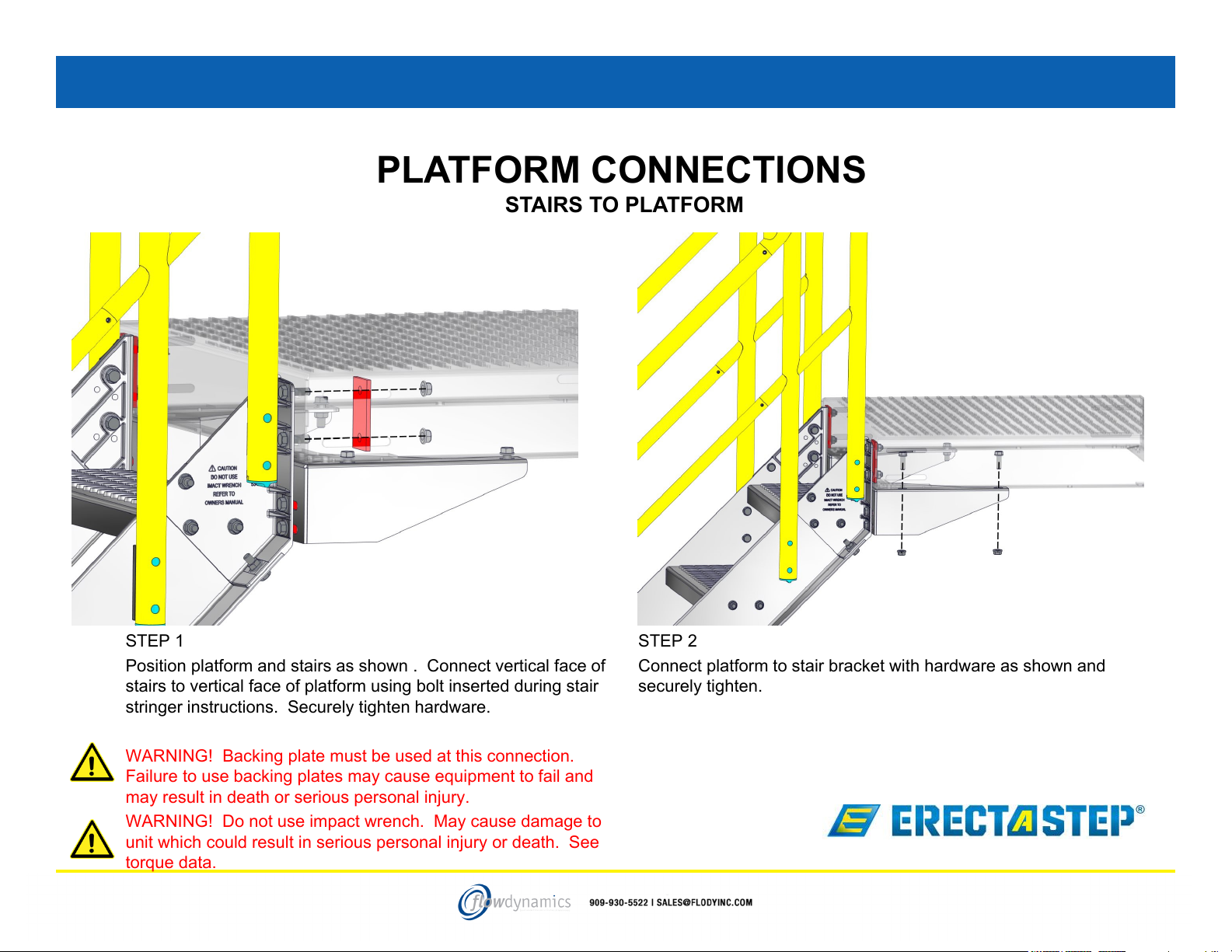
PLATFORM CONNECTIONS
STAIRS TO PLATFORM
STEP 1
Position platform and stairs as shown . Connect vertical face of
stairs to vertical face of platform using bolt inserted during stair
stringer instructions. Securely tighten hardware.
WARNING! Backing plate must be used at this connection.
Failure to use backing plates may cause equipment to fail and
may result in death or serious personal injury.
WARNING! Do not use impact wrench. May cause damage to
unit which could result in serious personal injury or death. See
torque data.
4-29-16
STEP 2
Connect platform to stair bracket with hardware as shown and
securely tighten.
38
Page 40
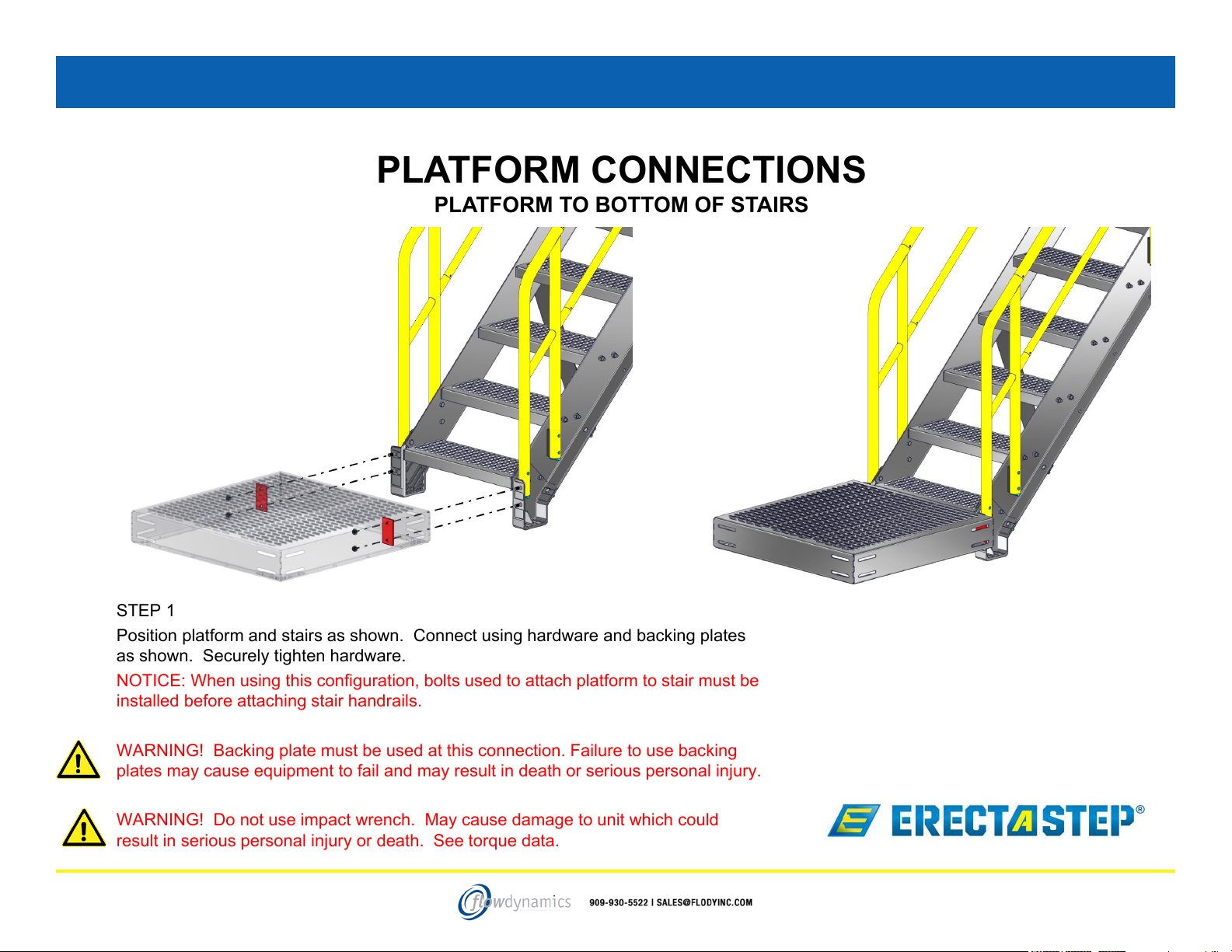
PLATFORM CONNECTIONS
PLATFORM TO BOTTOM OF STAIRS
STEP 1
Position platform and stairs as shown. Connect using hardware and backing plates
as shown. Securely tighten hardware.
NOTICE: When using this configuration, bolts used to attach platform to stair must be
installed before attaching stair handrails.
WARNING! Backing plate must be used at this connection. Failure to use backing
plates may cause equipment to fail and may result in death or serious personal injury.
WARNING! Do not use impact wrench. May cause damage to unit which could
result in serious personal injury or death. See torque data.
4-29-16
39
Page 41
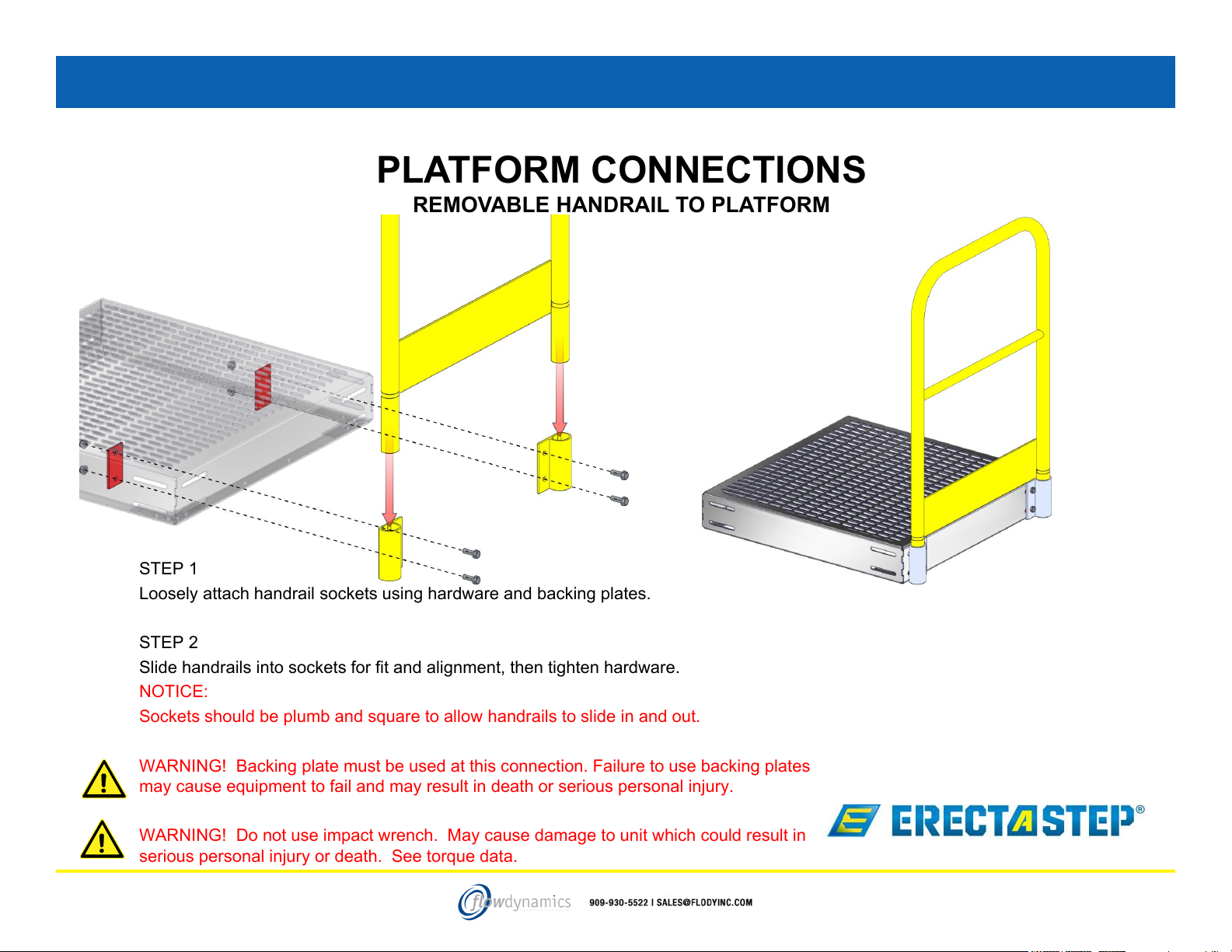
PLATFORM CONNECTIONS
REMOVABLE HANDRAIL TO PLATFORM
STEP 1
Loosely attach handrail sockets using hardware and backing plates.
4-29-16
STEP 2
Slide handrails into sockets for fit and alignment, then tighten hardware.
NOTICE:
Sockets should be plumb and square to allow handrails to slide in and out.
WARNING! Backing plate must be used at this connection. Failure to use backing plates
may cause equipment to fail and may result in death or serious personal injury.
WARNING! Do not use impact wrench. May cause damage to unit which could result in
serious personal injury or death. See torque data.
40
Page 42
HARDWARE CONNECTIONS
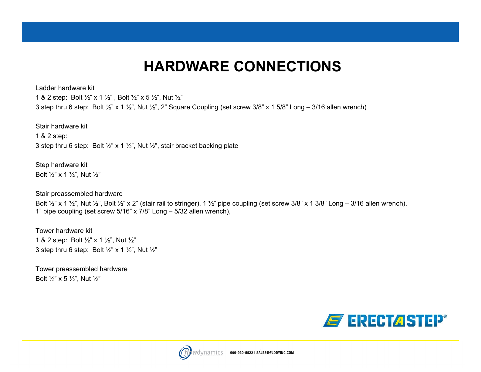
Ladder hardware kit
1 & 2 step: Bolt ½” x 1 ½” , Bolt ½” x 5 ½”, Nut ½”
3 step thru 6 step: Bolt ½” x 1 ½”, Nut ½”, 2” Square Coupling (set screw 3/8” x 1 5/8” Long – 3/16 allen wrench)
Stair hardware kit
1 & 2 step:
3 step thru 6 step: Bolt ½” x 1 ½”, Nut ½”, stair bracket backing plate
Step hardware kit
Bolt ½” x 1 ½”, Nut ½”
Stair preassembled hardware
Bolt ½” x 1 ½”, Nut ½”, Bolt ½” x 2” (stair rail to stringer), 1 ½” pipe coupling (set screw 3/8” x 1 3/8” Long – 3/16 allen wrench),
1” pipe coupling (set screw 5/16” x 7/8” Long – 5/32 allen wrench),
Tower hardware kit
1 & 2 step: Bolt ½” x 1 ½”, Nut ½”
3 step thru 6 step: Bolt ½” x 1 ½”, Nut ½”
Tower preassembled hardware
Bolt ½” x 5 ½”, Nut ½”
414-29-16
Page 43
SYSTEM DESIGN
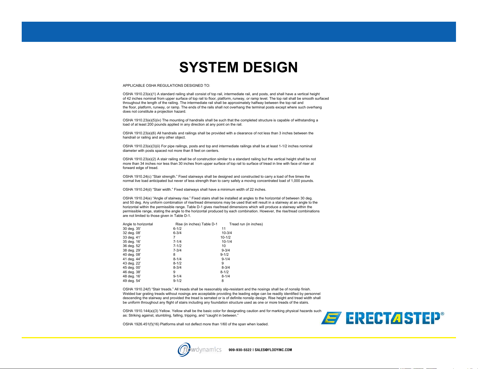
APPLICABLE OSHA REGULATIONS DESIGNED TO:
OSHA 1910.23(e)(1) A standard railing shall consist of top rail, intermediate rail, and posts, and shall have a vertical height
of 42 inches nominal from upper surface of top rail to floor, platform, runway, or ramp level. The top rail shall be smooth surf aced
throughout the length of the railing. The intermediate rail shall be approximately halfway between the top rail and
the floor, platform, runway, or ramp. The ends of the rails shall not overhang the terminal posts except where such overhang
does not constitute a projection hazard.
OSHA 1910.23(e)(5)(iv) The mounting of handrails shall be such that the completed structure is capable of withstanding a
load of at least 200 pounds applied in any direction at any point on the rail.
OSHA 1910.23(e)(6) All handrails and railings shall be provided with a clearance of not less than 3 inches between the
handrail or railing and any other object.
OSHA 1910.23(e)(3)(ii) For pipe railings, posts and top and intermediate railings shall be at least 1-1/2 inches nominal
diameter with posts spaced not more than 8 feet on centers.
OSHA 1910.23(e)(2) A stair railing shall be of construction similar to a standard railing but the vertical height shall be not
more than 34 inches nor less than 30 inches from upper surface of top rail to surface of tread in line with face of riser at
forward edge of tread.
OSHA 1910.24(c) “Stair strength.” Fixed stairways shall be designed and constructed to carry a load of five times the
normal live load anticipated but never of less strength than to carry safely a moving concentrated load of 1,000 pounds.
OSHA 1910.24(d) “Stair width.” Fixed stairways shall have a minimum width of 22 inches.
OSHA 1910.24(e) “Angle of stairway rise.” Fixed stairs shall be installed at angles to the horizontal of between 30 deg.
and 50 deg. Any uniform combination of rise/tread dimensions may be used that will result in a stairway at an angle to the
horizontal within the permissible range. Table D-1 gives rise/tread dimensions which will produce a stairway within the
permissible range, stating the angle to the horizontal produced by each combination. However, the rise/tread combinations
are not limited to those given in Table D-1.
Angle to horizontal Rise (in inches) Table D-1 Tread run (in inches)
30 deg. 35’ 6-1/2 11
32 deg. 08’ 6-3/4 10-3/4
33 deg. 41’ 7 10-1/2
35 deg. 16’ 7-1/4 10-1/4
36 deg. 52’ 7-1/2 10
38 deg. 29’ 7-3/4 9-3/4
40 deg. 08’ 8 9-1/2
41 deg. 44’ 8-1/4 9-1/4
43 deg. 22’ 8-1/2 9
45 deg. 00’ 8-3/4 8-3/4
46 deg. 38’ 9 8-1/2
48 deg. 16’ 9-1/4 8-1/4
49 deg. 54’ 9-1/2 8
OSHA 1910.24(f) “Stair treads.” All treads shall be reasonably slip-resistant and the nosings shall be of nonslip finish.
Welded bar grating treads without nosings are acceptable providing the leading edge can be readily identified by personnel
descending the stairway and provided the tread is serrated or is of definite nonslip design. Rise height and tread width shall
be uniform throughout any flight of stairs including any foundation structure used as one or more treads of the stairs.
OSHA 1910.144(a)(3) Yellow. Yellow shall be the basic color for designating caution and for marking physical hazards such
as: Striking against, stumbling, falling, tripping, and “caught in between.”
OSHA 1926.451(f)(16) Platforms shall not deflect more than 1/60 of the span when loaded.
424-29-16
 Loading...