

Page 1
MT STAR AG Indice : 1 18/10/2016
1 / 25
MT CAM AG_v1.doc
CCAAMM RRAACCEERR
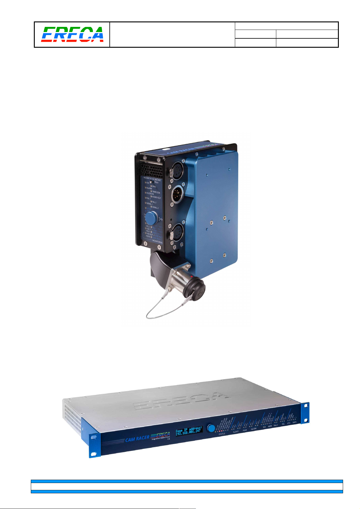
12G-SDI Dockable optical fiber transmission unit
for HD / 3G / 4K / 8K Camera.
TECHNICAL PRESENTATION
ERECA SAS 75 rue d'Orgemont, 95210 SAINT GRATIEN France Tel +33 1 39 89 76 23 www.ereca.fr
Page 2

MT STAR AG Indice : 1 18/10/2016
2 / 25
MT CAM AG_v1.doc
CONTENTS
CONTENTS ........................................................................................................................................................ 2
1 CAM RACER OVERVIEW .......................................................................................................................... 3
1.1 Key features ........................................................................................................................................ 3
1.2 Signal capacity .................................................................................................................................... 3
2 DETAILED DESCRIPTION ......................................................................................................................... 4
2.1 CAMERA UNIT Connectors location .................................................................................................. 4
2.2 BASESTATION Connectors location .................................................................................................. 5
2.3 Connectors description ....................................................................................................................... 5
2.3.1 SDI channels ................................................................................................................................... 5
2.3.2 SDI Monitoring ................................................................................................................................. 5
2.3.3 Ethernet ports .................................................................................................................................. 6
2.3.4 Composite input 1 specificity ........................................................................................................... 6
2.3.5 RJ45 DATA1 on Camera Head ....................................................................................................... 6
2.3.6 RJ45 DATA1 on Base station ......................................................................................................... 6
2.3.7 RJ45 DATA2 on Base station ......................................................................................................... 7
2.3.8 Intercom and Tally ........................................................................................................................... 7
2.3.9 Intercom pinout ................................................................................................................................ 8
2.3.10 Noble audio ................................................................................................................................. 8
2.3.11 Optionnal connector .................................................................................................................... 9
2.3.12 Lanc connector .......................................................................................................................... 10
2.3.13 Optical Connectors .................................................................................................................... 10
2.4 Display unit ........................................................................................................................................ 11
2.4.1 Camera head ................................................................................................................................. 11
2.4.2 Basestation .................................................................................................................................... 13
2.5 Remote power section ...................................................................................................................... 16
2.5.1 Main power section ....................................................................................................................... 16
2.5.2 8.4V regultator option. ................................................................................................................... 16
2.6 Audio mixer ....................................................................................................................................... 17
2.7 Intercom behaviour ........................................................................................................................... 17
2.7.1 2 channels intercom ...................................................................................................................... 17
2.7.2 Separate intercoms ....................................................................................................................... 18
3 WEB MANAGEMENT ............................................................................................................................... 18
3.1 Essentials .......................................................................................................................................... 18
3.2 Status page ....................................................................................................................................... 19
3.2.1 Signal activity ................................................................................................................................ 19
3.2.2 Alarms display ............................................................................................................................... 19
3.3 Measures page ................................................................................................................................. 20
3.3.1 General details .............................................................................................................................. 20
3.3.2 Optical details ................................................................................................................................ 20
3.4 Settings page .................................................................................................................................... 21
3.4.1 Microphones SUB section ............................................................................................................. 21
3.4.2 Volumes settings sub section ........................................................................................................ 22
3.4.3 Various settings sub section ......................................................................................................... 22
3.4.4 Save recall ..................................................................................................................................... 22
3.5 Configuration page ............................................................................................................................ 23
3.5.1 General configuration .................................................................................................................... 23
3.5.2 IP address ..................................................................................................................................... 23
3.5.3 Settings protection ......................................................................................................................... 23
3.5.4 Change password ......................................................................................................................... 24
4 TECHNICAL SPECIFICATIONS ............................................................................................................... 25
ERECA SAS 75 rue d'Orgemont, 95210 SAINT GRATIEN France Tel +33 1 39 89 76 23 www.ereca.fr
Page 3

MT CAM AG_v1.doc
MT STAR AG Indice : 1 18/10/2016
3 / 25
1 CAM RACER OVERVIEW
The CAM RACER is a complete optical fiber transmission solution for camera connexion for OB Van, Studio
and Cinema applications. It is composed of a camera dockable transmitter and a 1RU basestation receiver.
1.1 KEY FEATURES
The following key features makes the CAM RACER a product of choice for all kind of production from HD to
8K applications.
• Transmit Two 12G-SDI channels plus two 3G-SDI channels.
• Power unit delivers 140 Watts to the camera after 450 meter of standard 9.2mm SMPTE cable.
• An automatic battery backup will help the remote powering system if more power is needed suddenly.
• Signals control and Setup is done through internal web server. Most signals are also reported on LED
display of each unit.
• An Oled display gives direct access to optical receiving levels and internal web server IP address.
• An internal audio mixer allows user to mix between talkback, programs inputs and local audio channels
for Eng and Reporter headsets.
• Camera control channel supports: Ethernet, RS422 Serial, Canon RC-V100 protocol (Enhanced Lanc).
• Camera synchronization supports: Two composite video signals and one Time code.
1.2 SIGNAL CAPACITY
Each CAM Racer comes in standard with the following signal set:
•
2 3G / HD / SD signals from Camera,
•
1 Viewfinder HDSDI from basestation,
•
1 Monitoring HDSDI from the camera (HDMI or BNC input autoswitch),
•
2 Genlock from basestation (Composite video / Black burst / Tri-level),
•
2 Bidirectionnal audio with mic preamp and phantom power at camera side,
•
1 Intercom in/out with headset interface at camera side,
•
1 Time code from basestation,
•
1 Ethernet 10/100 Mbps,
•
1 Serial data RS 232/422/485,
•
1 Canon RC-V100 protocol (Enhanced Lanc),
•
1 Red Tally Contact closure from basestation.
Two options are available for more complex setups (4K/8K, 2 Intercom separate headsets):
•
2 extra 12G / 6G / 3G / HD / SD signals from Camera (board addon),
•
2nd Intercom in/out with headset interface at camera side +
2nd Tally (Green) Contact closure from basestation +
2nd Serial data RS 232/422/485 (connector addon).
ERECA SAS 75 rue d'Orgemont, 95210 SAINT GRATIEN France Tel +33 1 39 89 76 23 www.ereca.fr
Page 4
MT CAM AG_v1.doc
MT STAR AG Indice : 1 18/10/2016
4 / 25
2 DETAILED DESCRIPTION
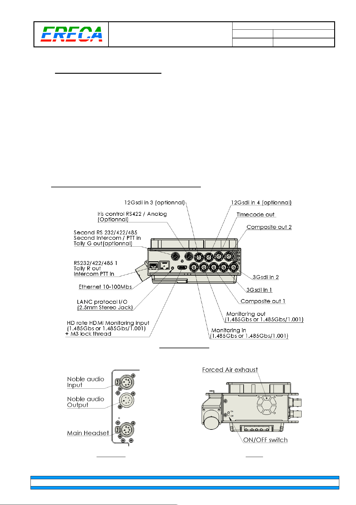
The transmitter is fitted in a battery (V-mount or AB) dockable unit able to be installed on every camera. All
connectors are standard and located on the right side of the unit. Audio and intercom connectors are located
at the rear of the unit along the battery.
A user panel feature LEDs for signal presence/activity, rotary button for volume adjustment and various level
settings (sidetone, program1 / program2 listen level) and push to talk commands. Red/green tally led are
located on top of the unit.
Cooling of the unit is done by a small and silent fan located at the back of the unit.
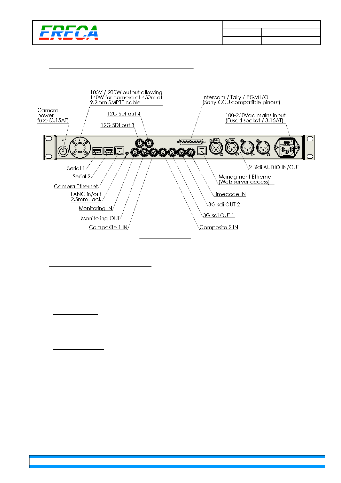
The basestation receiver is integrated in a standard 19” 1RU format. All signals are dispatched on standard
connectors and standard pinout at the rear of the chassis. (Web server is on a separate Ethernet port).
The front of the chassis is composed of a LED display panel indicating the status of each signals and
technical alarms. An Oled display gives direct access to optical receiving levels and server IP address.
The basestation integrates a single mains power supply and two fans for thermal management.
2.1 CAMERA UNIT CONNECTORS LOCATION
Right side connectors.
ERECA SAS 75 rue d'Orgemont, 95210 SAINT GRATIEN France Tel +33 1 39 89 76 23 www.ereca.fr
Audio XLR’s. Bottom.
Page 5
MT STAR AG Indice : 1 18/10/2016
2.2 BASESTATION CONNECTORS LOCATION
5 / 25
MT CAM AG_v1.doc
Basestation connectors.
2.3 CONNECTORS DESCRIPTION
Digital video, Composite video and Timecode I/O’s are on standard size BNC.
The pinout and specificities of the remaining connectors is detailed in the following sections.
2.3.1 SDI CHANNELS
3G channels supports from 270Mbs to 3Gbs, 12G channels supports from 270Mbs to 12Gbs.
All channels are reclocked and support RAW formats.
2.3.2 SDI MONITORING
Monitoring channel is transmitted by TDM along the other low datarate signals and supports only HD rates
(1.485GBs or 1.485/1.001 Gbs), the ANC part of the signal SDI is transmitted (Embedded audio etc).
At camera side the monitoring input can be either SDI or HDMI autosense. If both signals are fed to the
camera unit the selector will use the first valid signal detected.
Note: The HDMI audio is not re embedded in the Monitoring SDI signal transmitted to the basestation.
ERECA SAS 75 rue d'Orgemont, 95210 SAINT GRATIEN France Tel +33 1 39 89 76 23 www.ereca.fr
Page 6
MT CAM AG_v1.doc
1: GND (Shield for seri
al channel)
1: GND (Shield for serial channel)
25
6 /
MT STAR AG Indice : 1 18/10/2016
2: PTT input (Intercom Channel 1 / ENG)
3: RX RS 422 – (Cam racer electrical OUTPUT)
4: TX RS 422 – (Cam racer electrical INPUT)
5: TX RS 422 + (Cam racer electrical INPUT)
6: RX RS 422 + (Cam racer electrical OUTPUT)
7: TALLY Red OUT
8: TALLT Red OUT
8
1
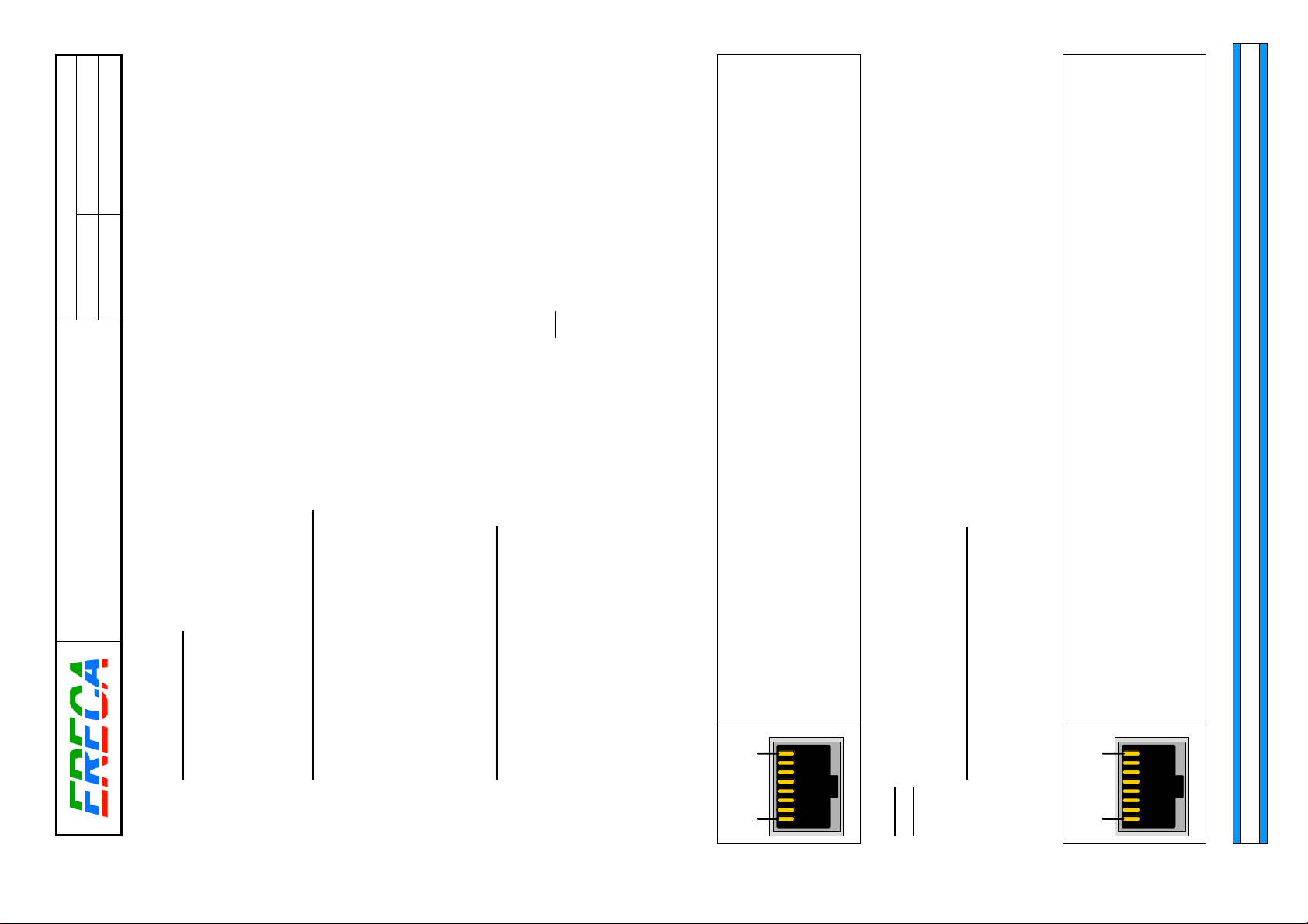
2.3.3 ETHERNET PORTS
Ethernet interfaces are 10-100 Mb/s autosense.
The camera ports are both Auto Crossover and will work with any type of cables.
The admin port is not Auto Crossover and will require a crossed cable to work directly with a computer.
2.3.4 COMPOSITE INPUT 1 SPECIFICITY
This channel is mainly used for Genlocking the camera on the studio Black-Burst.
In order to ease the distribution of Genlock to many cam racers by using BNC T’s only, the Composite 1
input impedance can be turned to High Impedance.
To do so, go to the settings webpage of the units and tick the “High impedance for composite 1” on most of
the cam racer’s. The last unit fed by the signal will remain with 75 Ohms input impedance (“High impedance
for composite 1” = unticked).
2.3.5 RJ45 DATA1 ON CAMERA HEAD
The RJ 45 connector provide 1 differential pair for RS422 transmit and 1 differential pair for RS422 receive.
Max bitrate is 500 Kbds.
For RS485 also setup the corresponding Baud rate within the web server to enable the cam racer to
manage output impedance at the right serial byte duration.
To build half duplex RS485 transmission just bridge pins 3 with pin 4 and pin 5 with pin 6.
Shorting pin 1 and 2 will trigger the Intercom for talking on channel 1. Pins 7 and 8 are shorted at camera side (Floating dry contact) when tally RED is triggered at base station.
Note2: For RS 232 pin 3 is cam racer output, pin 4 is cam racer input. Leave pins 5 and 6 unconnected.
Note1: For RS 485 Telex/RTS talkback panels please ask ERECA for wiring tip.
2.3.6 RJ45 DATA1 ON BASE STATION
For serial channel the settings are the same as above (See camera head section).
An extra power output is provided to ease wiring of each RCP to the base station without power harness.
2: Green Tally input (Short to ground to trig)
3: RX RS 422 – (Cam racer electrical OUTPUT)
4: TX RS 422 – (Cam racer electrical INPUT)
5: TX RS 422 + (Cam racer electrical INPUT)
6: RX RS 422 + (Cam racer electrical OUTPUT)
7: +12 Volts output for RCP power ( 1 Amp maximum, protected with resettable fuse)
8: Ground
8
1
ERECA SAS 75 rue d'Orgemont, 95210 SAINT GRATIEN France Tel +33 1 39 89 76 23 www.ereca.fr
Page 7
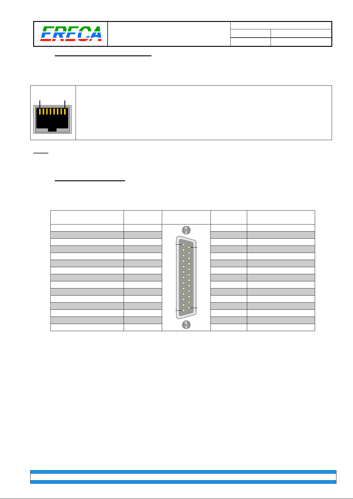
1: GND (Shield
for serial channel
)
Socket
D SUB 25
Socket
Intercom 1 OUT+
1 14
Intercom 2 OUT+
Intercom 1 OUT
- 2 15 Intercom 2 OUT
- GND
3 16
GND
Intercom 1 IN+
4 17
Intercom 2 IN+
Intercom 1 IN
- 5 18 Intercom 2 IN
- PGM1 IN +
6 19
PGM1 IN +
PGM1 IN
- 7 20 PGM1 IN
- GND
8 21
GND
GND
9 22
AUX4 input
AUX3 input
10 23
AUX5 input
RED TALLY IN+
11 24
GREEN TALLY IN+
RED TALLY IN
- 12 25 GREEN TALLY IN
- Chass
is GND
13
MT STAR AG Indice : 1 18/10/2016
7 / 25
2.3.7 RJ45 DATA2 ON BASE STATION
For serial channel the settings are the same as above (See camera head section).
MT CAM AG_v1.doc
1
2: Red Tally input (Short to ground to trig)
8
3: RX RS 422 – (Cam racer electrical OUTPUT)
4: TX RS 422 – (Cam racer electrical INPUT)
5: TX RS 422 + (Cam racer electrical INPUT)
6: RX RS 422 + (Cam racer electrical OUTPUT)
7: Unconnected
8: Unconnected
Note: This connector is fitted in standard on every base station, but the serial signals are routed on an
optional multipin connector on the camera unit. (See section 2.3.1.1 for shared pinout details).
2.3.8 INTERCOM AND TALLY
Intercom audio and tally are located on a DSUB 25 Female connector with same pinout as other popular
CCU’s.
contact
Intercom/Tally
1
14
contact
SIGNAL
13
25
Output signal amplitude is around 0dBm with standard dynamic mike headsets.
Input amplitude can go up to +18Dbm.
Tally inputs are trigged by a dry contact or by a potential greater or equal to 5 volts applied to pins 11 or 24
respective to ground or pins 12, 25. Selection between the two options is done at the bottom of the settings
web page.
AUX3 to AUX5 pins are seen by the basestation unit but have no internal actions for the moment.
All the ground pins are tied together inside the equipment.
ERECA SAS 75 rue d'Orgemont, 95210 SAINT GRATIEN France Tel +33 1 39 89 76 23 www.ereca.fr
Page 8
MT CAM AG_v1.doc
MT STAR AG Indice : 1 18/10/2016
8 / 25
2.3.9 INTERCOM PINOUT
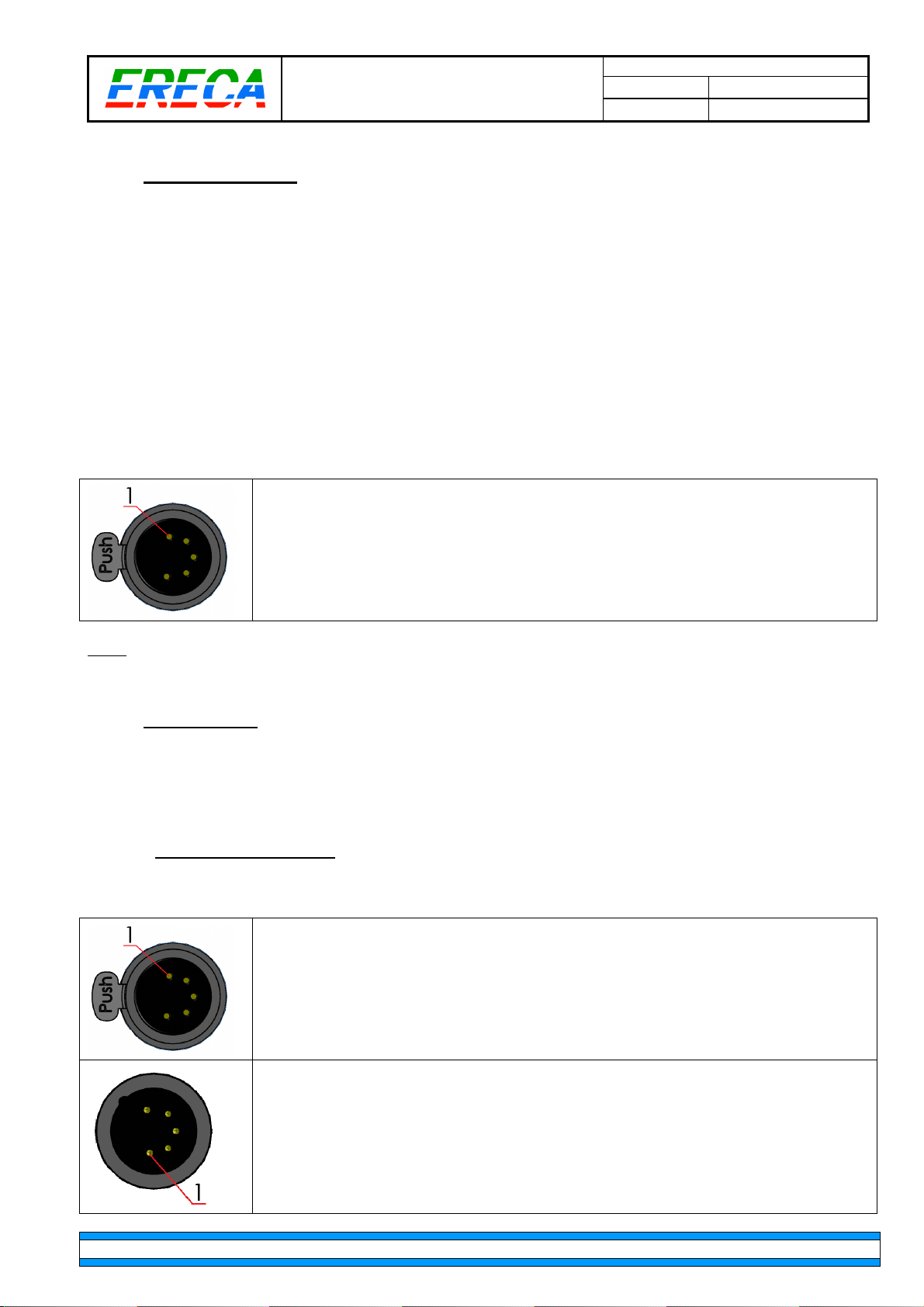
Intercom XLR is 5 pins Female with common pinout. Intercom microphone type can be:
•
Dynamic,
•
Asymmetric dynamic (most common),
•
Electret or Carbon (8 V / 470 Ohms polarization),
•
Fully static with 48V phantom power.
The microphone type selection and gain setting is done on the top of the settings webpage in a zone called
“intercom mic”.
For Dynamic or Fully static microphone pin 1 become the negative input of the mic section, in this case use
pin 3 for shielding. For the other types pin 1 is automatically tied to ground internally.
The output impedance of the earpiece amplifier is 20 Ohms and suitable for 50 to 600 Ohms headsets.
1: Mic input – or Mic Shield,
2: Mic input +,
3: Ground for Earpiece,
4: Ear piece,
5: NC(default) or special use, see note.
Note: Upon request pin 5 can either be shorted internally to pin 4 for stereo headsets or routed on the
output of the second headphone amplifier to hear only the second intercom channel on pin 5.
2.3.10 NOBLE AUDIO
A stereo bidirectional channel is available between the two units. At Camera side, the input can be either
line level or with built in mic gains and phantom power. Setting is done on the top of the settings webpage in
a zone called “XLR mic”.
2.3.10.1 CAMERA SIDE PINOUT
Camera XLR are 5 pins models, pinout is as follows.
1: Channel 1 Input +,
2: Channel 1 Input -,
3: Ground,
4: Channel 2 Input -,
5: Channel 2 Input +.
1: Channel 1 Output +,
2: Channel 1 Output -,
3: Ground,
4: Channel 2 Output -,
5: Channel 2 Output +.
ERECA SAS 75 rue d'Orgemont, 95210 SAINT GRATIEN France Tel +33 1 39 89 76 23 www.ereca.fr
Page 9
MT STAR AG Indice : 1 18/10/2016
9 / 25
2.3.10.2 BASESTATION PINOUT
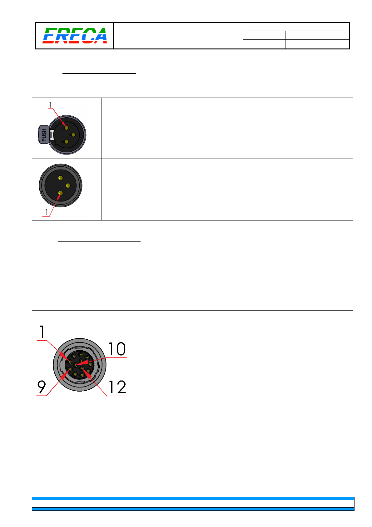
Basestation are on standard 3 pins XLR’s, pinout is as follows for each channels.
1: Ground,
2: Input +,
3: Input -.
1: Ground,
2: Output +,
3: Output -.
MT CAM AG_v1.doc
2.3.11 OPTIONNAL CONNECTOR
At camera side an optional connector give access to the following signals
•
2nd Intercom in/out with headset interface at camera side,
•
2nd Tally (Green) Contact closure from basestation,
•
2nd Serial data RS 232/422/485.
Connector socket is Hirose HR10A-10R-12S (mate with HR10A-10P-12P), pinout is a follows:
1: RX RS 422 – (Cam racer electrical OUTPUT),
2: RX RS 422 + (Cam racer electrical OUTPUT),
3: Ground,
4: Intercom 2 Mic input +,
5: Intercom 2 Mic input - / Shield,
6: +14V output (1A internal resettable fuse),
7: Green Tally ground closure,
8: Intercom 2 PTT input,
9: Intercom 2 Earpiece,
10: Reserved / Do not connect,
11: TX RS 422 + (Cam racer electrical INPUT),
12: TX RS 422 - (Cam racer electrical INPUT).
Serial 2 settings and behavior are the same as for serial 1 interface.
Intercom 2 will work only if “separated intercoms” choice is selected in the settings webpage. Settings and
and electrical specifications are the same as for intercom 1.
In this case only channel 1 is routed to intercom 1 XLR socket and channel 2 is routed to intercom 2 on this
Hirose 12 socket.
When “monoral intercom” is set pin 8 acts as a third PTT input to ease external wiring.
ERECA SAS 75 rue d'Orgemont, 95210 SAINT GRATIEN France Tel +33 1 39 89 76 23 www.ereca.fr
Page 10

MT CAM AG_v1.doc
MT STAR AG Indice : 1 18/10/2016
10 / 25
2.3.12 LANC CONNECTOR
Lanc connector is a 2.5mm stereo jack on each units. Protocol supported is RC-V100.
Tip is Lanc signal and Ring is +5V output trough a 10 Ohms serial resistor for remote control power.
The 10 Ohms serial resistor is also fitted in the cam racer Head unit, we suggest to leave the ring
unconnected in your cable.
Caution: Lanc management is not symmetric, the camera must be connected on camera head unit and the
remote connected on the basestation unit.
2.3.13 OPTICAL CONNECTORS
The CAM Racer stage racer uses the two fibers of the SMPTE cable for signal transmission.
One fiber is used bidirectionally with a 2.5Gbs TDM signal carrying all the low datarate signals and the HD
monitoring signal. The other fiber
The CAM Racer is available with the following optical terminals:
- LEMO 3K,
- NEUTRIK OPTICALCON Duo (Caution 100V remote power supply),
- Tyco MX or Fibreco Mini2 Expanded beam (Special request).
ERECA SAS 75 rue d'Orgemont, 95210 SAINT GRATIEN France Tel +33 1 39 89 76 23 www.ereca.fr
Page 11
MT CAM AG_v1.doc
MT STAR AG Indice : 1 18/10/2016
11 / 25
2.4 DISPLAY UNIT
2.4.1 CAMERA HEAD
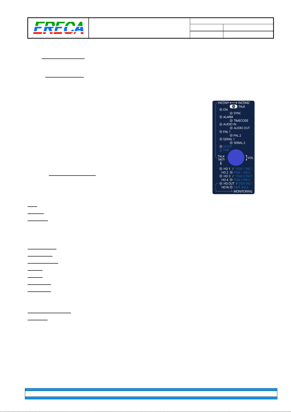
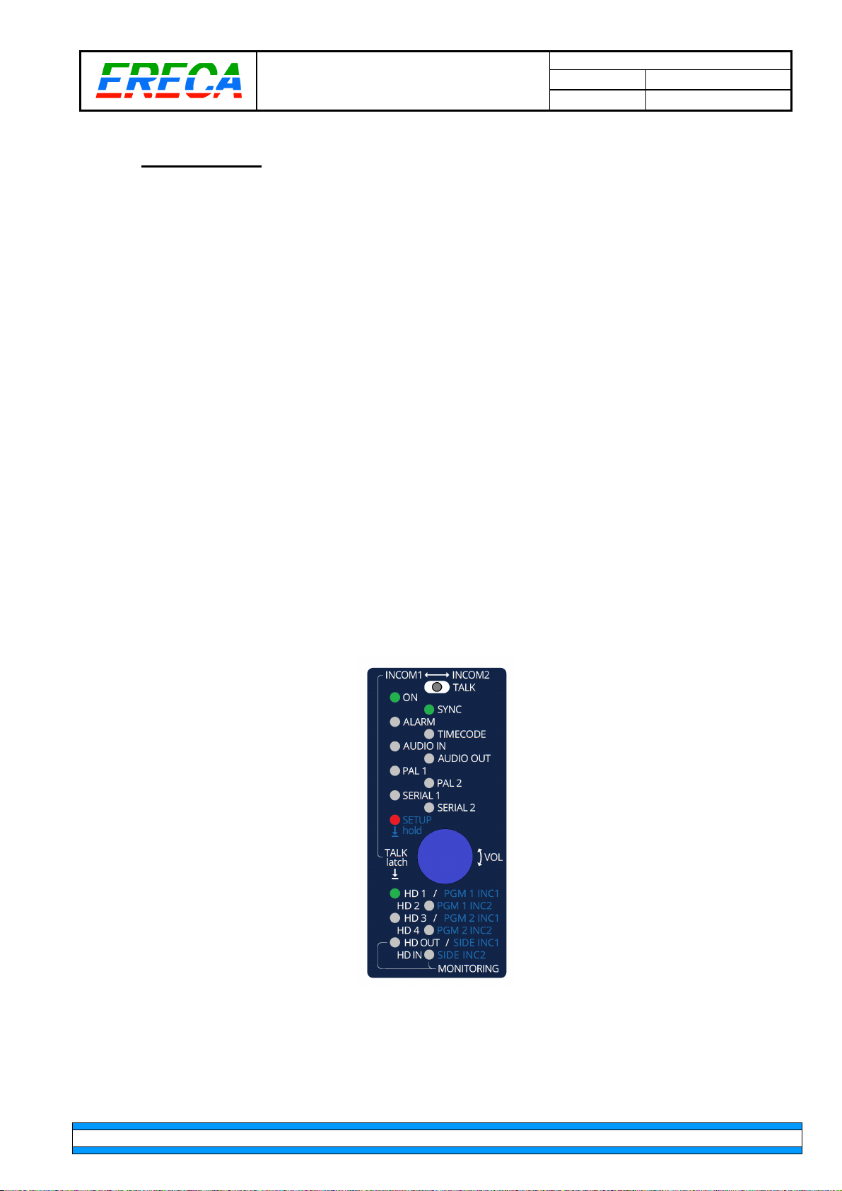
The display panel enables user to perfom Three different functions, the SETUP led indicates in which mode
is the display:
•
1) Monitor alarms and signal presence. (Setup OFF),
•
2) Various volume adjustments (Setup Lit Solid),
•
3) Monitor which Talkback channel is used (Setup Blinking).
Note also that all leds can be forced off from the webpage settings.
2.4.1.1 MODE 1 (NORMAL)
This is the default mode, in this mode the texts colored in white apply.
Major Status:
ON:
Green LED, ON when all internal supplies are within +/- 5% of target.
SYNC:
ALARM:
Green LED, ON when the unit is SYNC’ed on the basestation signal.
Red LED, ON when something is wrong in the unit (Bad optical power on the receiver, Too low or
too high laser current).
Various signal status:
TIMECODE:
AUDIO IN:
AUDIO OUT:
PAL1:
PAL2:
SERIAL1:
SERIAL2:
Green LED, ON when timecode is delivered on the camera unit output.
Green LED, ON when the optical power is low on main path.
Green LED, ON when the optical power is low on main path (if option fitted).
Green LED, ON when a composite/trilevel video is delivered on the camera unit output 1.
Green LED, ON when a composite/trilevel video is delivered on the camera unit output 2.
Green LED, ON when activity (TX or RX) on the serial port 1.
Green LED, ON when activity (TX or RX) on the serial port 2.
SDI signal status:
HD1 – HD4, HDIN:
HDOUT:
Led is lit Green if a valid HD signal is delivered to the Monitoring output port (Means that the
Corresponding led is lit Green if a SDI signal is detected on the corresponding input.
internal circuitry is able to extract the signal from the TDM and re-create the corresponding clock of
the signal fed at the basestation).
In this mode rotating the “Blue” button will adjust the global listen volume of the Intercom headset 1.
ERECA SAS 75 rue d'Orgemont, 95210 SAINT GRATIEN France Tel +33 1 39 89 76 23 www.ereca.fr
Page 12
MT CAM AG_v1.doc
MT STAR AG Indice : 1 18/10/2016
12 / 25
2.4.1.2 MODE 2 (SETUP)
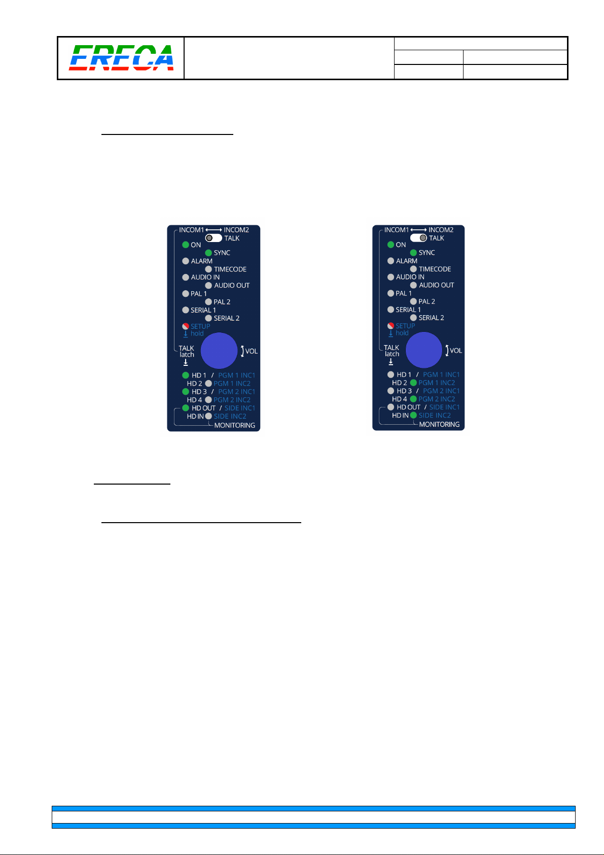
Setup is entered by a long press on the Blue button (3 second or more), then the SETUP led is lit Solid.
This mode enables the user to adjust, from the camera unit, the audio mixing level and the side tone heard
in both intercom headsets/channels.
The meaning of the “major status” and “various status” sections remain the same. The SDI signal status
change and the texts written in blue apply.
A single led will be lit in this section indicating what level will be adjusted by the blue button rotation.
On each short press (Less than 0.5 second) the indicating led will point the next level, if not desired, short
press again to go to the desired level. After the sixth level the led will point again the first one.
Adjustable levels are scrolled in this order:
•
PGM1 INC1: Listen level on PGM1 input,
•
PGM2 INC1: Listen level on PGM2 input,
•
SIDE INC1: Adjust sidetone level for headset 1 (Need to be in talk position),
•
PGM1 INC2: Listen level on PGM1 input,
•
PGM1 INC2: Listen level on PGM1 input,
•
SIDE INC2: Adjust sidetone level for headset 2 (Need to be in talk position).
The drawing below illustrate this mode.
ERECA SAS 75 rue d'Orgemont, 95210 SAINT GRATIEN France Tel +33 1 39 89 76 23 www.ereca.fr
Page 13
MT CAM AG_v1.doc
MT STAR AG Indice : 1 18/10/2016
13 / 25
2.4.1.3 MODE 3 INTERCOM TALK
The purpose of this mode is only to indicate visually that an intercom channel is used. The two examples
shown below illustrate what happen for each channel, note that the setup led is blinking.
The meaning of the “major status” and “various status” sections remain the same.
Talk on channel 1 Talk on channel 2
2.4.2 BASESTATION
2.4.2.1 OLED DISPLAY AND ROTARY BUTTON
An OLED display associated to a rotary button displays the most useful information related to the
Basestation / Camera Head pair.
Rotating the button will lit the OLED for 30 seconds and display the following infos:
•
User camera name (Set in the basestation webserver),
•
Basetsation IP address,
•
Optical power received by the Camera Head unit,
•
Optical power received by the Basestation unit,
•
Optical power received by HD1 video receiver,
•
Optical power received by HD2 video receiver,
•
Optical power received by HD3 video receiver,
•
Optical power received by HD4 video receiver.
ERECA SAS 75 rue d'Orgemont, 95210 SAINT GRATIEN France Tel +33 1 39 89 76 23 www.ereca.fr
Page 14
MT STAR AG Indice : 1 18/10/2016
14 / 25
2.4.2.2 GENERAL STATUS LED’S
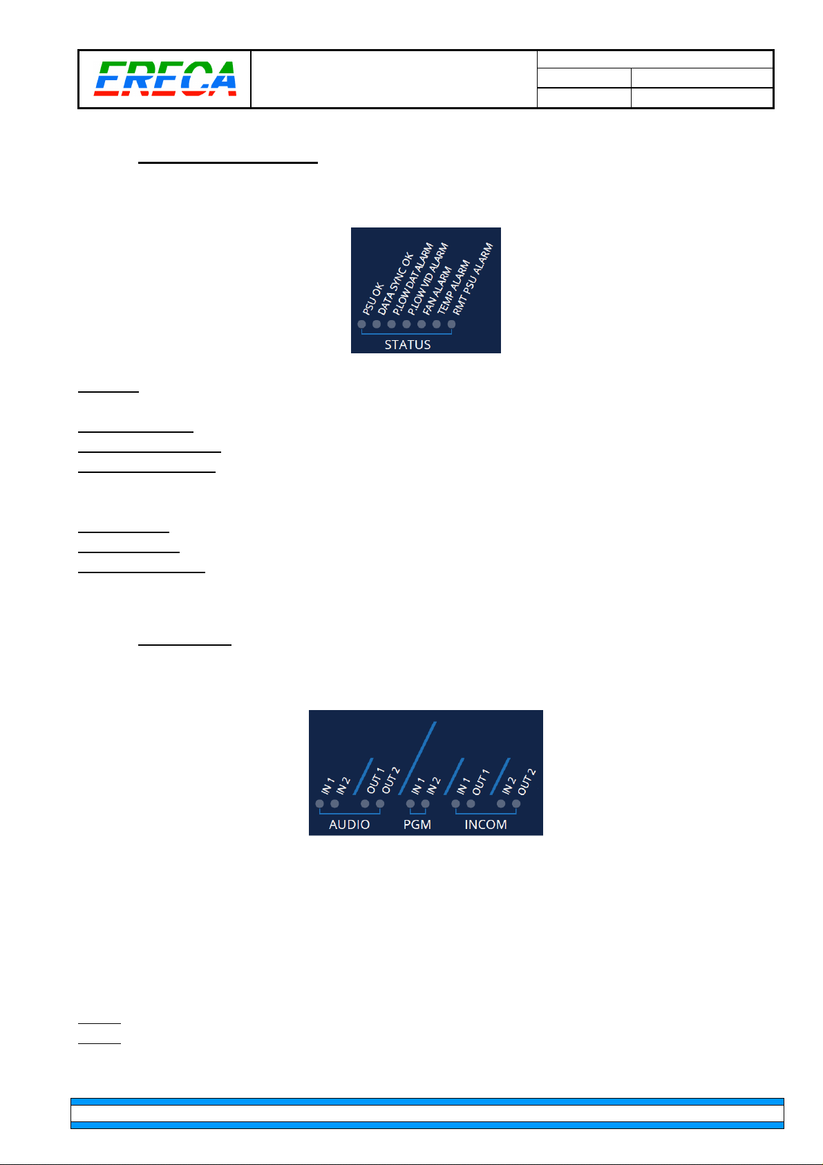
This section groups technical alarms / main information of the transmission unit.
PSU OK:
Green LED, ON if all internal voltages are OK (within +/-5% tolerance).
DATA SYNC OK:
P.LOW DAT ALARM:
P.LOW VID ALARM:
Green LED, ON when Basestation is locked on the Camera unit TDM signal.
Red LED, ON when optical power seen by the TDM receivers are low (<-18dBm).
Red LED, ON when optical power seen by a HD receiver is low,
(< -18dBm for 3G channels 1 &2, < -13dBm for 12G channels 3 & 4).
FAN ALARM:
TEMP ALARM:
RMT PSU ALARM:
Red LED, ON when a Fan in the basestation is broken or stuck.
Red LED, ON when the basestation internal temperature is over 60°C.
Red LED, ON when the source voltage of the remote power supply section is low.
MT CAM AG_v1.doc
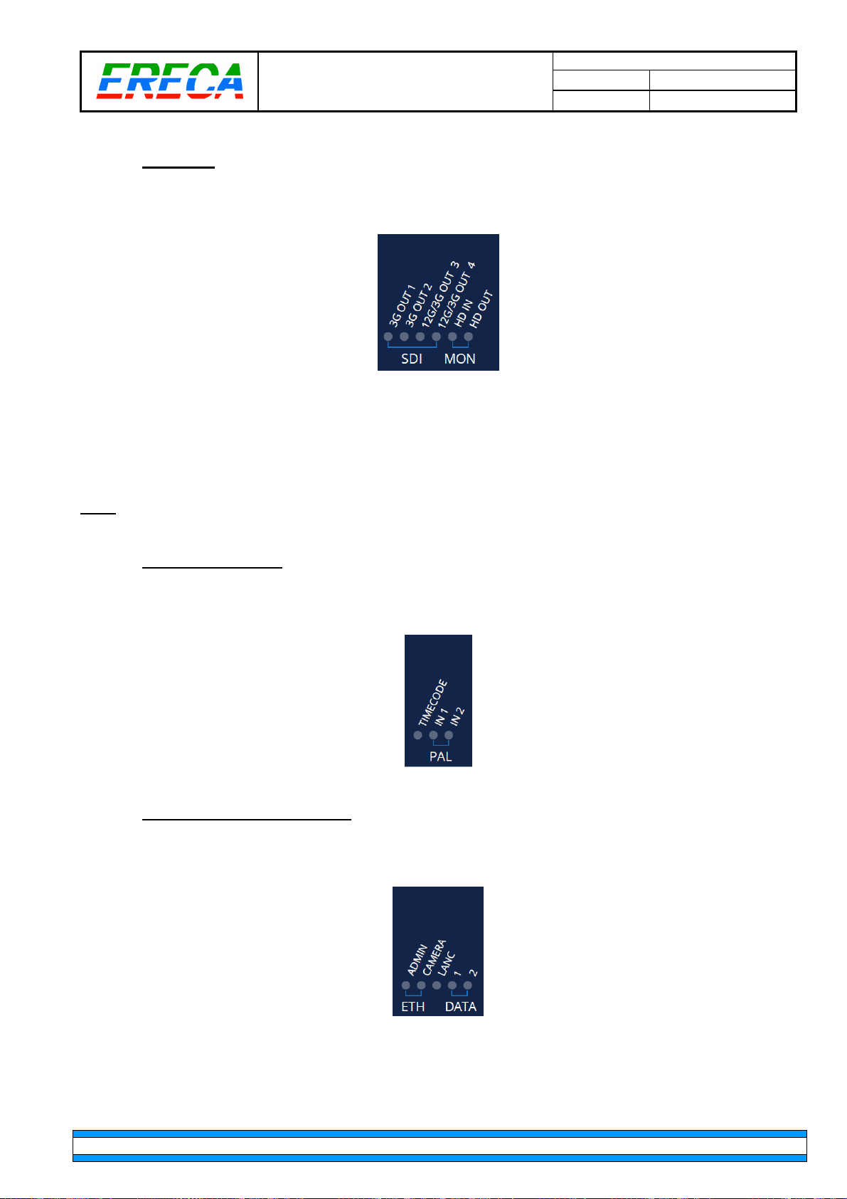
2.4.2.3 AUDIO LED’S
Audio presence / activity at basestation level is displayed in this section.
The “AUDIO” section indicates presence of signal on the noble audios XLR’s.
The “PGM” section indicates presence of signal on Program inputs of the basestation DSUB-25.
The “INCOM” section indicates presence of signal on the Intercom ports of the basestation.
For each channel the LEDs indicate audio activity on their respective input and output ports. The trigger
level is set to -10dBm approximatively. Audio activity LEDs are refreshed every 500ms displaying if there
was a level > -10dBm on the past 500ms period providing a smooth display.
Note1: “IN” means a signal entering the base station, “OUT” a signal going out of the basestation.
Note2:
The state of each led may be affected by the audio mixing programmed in the unit.
ERECA SAS 75 rue d'Orgemont, 95210 SAINT GRATIEN France Tel +33 1 39 89 76 23 www.ereca.fr
Page 15
MT CAM AG_v1.doc
MT STAR AG Indice : 1 18/10/2016
15 / 25
2.4.2.4 SDI LED’S
This section indicates SDI presence (Reclocker Locked) on each video receiver outputs of the basestation.
HD OUT indicates if a valid HD signal is delivered to the Monitoring output port (Means that the
Internal circuitry is able to extract the signal from the TDM and re-create the corresponding clock of
the signal fed at the camera unit).
HD IN indicates that a SDI signal is detected on the corresponding input whatever its data rate.
Note: The monitoring input will only work on a HD rate.
2.4.2.5 REFERENCE LED’S
All reference signals for camera are grouped in this section.
2.4.2.6 CONTROL CHANNELS LED’S
All control channels link/activity are grouped in this section.
The “ETH” leds are lit if the link is established with the pair device.
Any data activity on the LANC jack will lit the led regardless the protocol.
The “DATA” leds are lit if any activity on the corresponding serial channel.
ERECA SAS 75 rue d'Orgemont, 95210 SAINT GRATIEN France Tel +33 1 39 89 76 23 www.ereca.fr
Page 16
MT CAM AG_v1.doc
MT STAR AG Indice : 1 18/10/2016
16 / 25
2.5 REMOTE POWER SECTION
2.5.1 MAIN POWER SECTION
CAM Racer is basically remote powered from its base station. The basestation unit is able to source up to
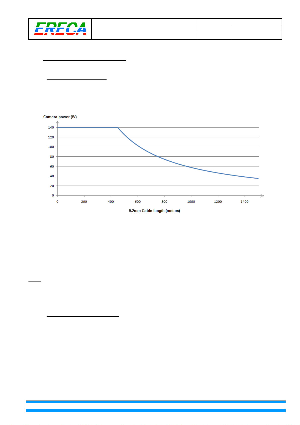
140W of power for the camera at 450m of 9.2mm SMPTE cable. For longer runs the amount of available
power will decrease as shown on the following curve.
An optional battery support (V-lock or AB Gold mount) enables the CAM racer and its camera to be locally
powered by a battery.
A key feature of the Cam racer is the automatic switching between remote power and battery power without
power loss for the CAM racer and its camera. On very long lengths of SMPTE a temporary sudden extra
consumption (camera startup, accessory startup) may draw too much power regarding the loss of the
installed SMPTE cable. In this case the CAM racer will detect power drop and will switch on the battery and
come back on the remote power supply to save battery energy.
Note: The power curve above represents power dissipated by a pure resistive load, camera inrush current or
accessories inrush current may exceed those limits and make the internal converter to stop briefly and
restart. We improve our power section as converters with less load sensivity arrive on the market.
For this kind of application we suggest using our automatic battery backup principle.
2.5.2 8.4V REGULTATOR OPTION.
CAM racer is also designed for small power consumption devices like Canon C300/C500.
Upon request the remote power section is suppressed at both ends. The lock battery option powers the
Cam racer and fits an internal hi efficiency voltage regulator to deliver 8.4Volts 32Watts for the Canon
Camera over a dedicated D-Tap connector.
Upon request the 8.4V regulator can also be fitted on regular units with a dedicated D-TAP output.
ERECA SAS 75 rue d'Orgemont, 95210 SAINT GRATIEN France Tel +33 1 39 89 76 23 www.ereca.fr
Page 17

MT CAM AG_v1.doc
MT STAR AG Indice : 1 18/10/2016
17 / 25
2.6 AUDIO MIXER
The Cam racer basestation audio section provides a small mixer that enables to send to each internal audio
channel transmitted to the camera (Intercom1, Intercom2, Audio1, Audio2) a mix of the 6 physical input
sources (Intercom1, Intercom2, Pgm1, Pgm2, Audio1, Audio2).
Depending on the application, any user can hear the desired audio mix in his headset or earpiece.
This useful feature also avoids any complex cabling between an external audio mixer and the cam racer
basestations.
This setting is done within the “volume settings” section of the settings web page. A small mixer subset is
available for each audio going to the camera
To add a source to the mix, firstly tick the “reinject” box and secondly adjust the desired level.
For multiple setting, use the Download / Import configuration at the bottom of the settings pages to Save /
Recover settings from your computer.
2.7 INTERCOM BEHAVIOUR
Intercom have 2 operation modes:
•
Single headset with 2 channels (Most common).
•
Separate headset with 1 channel on each headset.
The selection is done with the combo box named “Intercom mode”
The Talk / Talk latch action can be done directly on the camera unit or trough ground closures located at
SERIAL 1 RJ45 or on the Hirose12 Multipin depending of the mode choosen.
Talk latch is enabled by pressing momentaneously (> 0.5 second) the talk button on the desired channel.
After this delay the unit will turn to simple Push to Talk and will close the channel upon button release.
2.7.1 2 CHANNELS INTERCOM
Talk command sources are:
•
Camera unit button (enable talk on channel1 and/or chennel2),
•
Serial 1 RJ45 ground closure (enable talk on channel1),
•
Ground closure on the Hirose 12 connector (enable talk on channel1).
By default or when talking on channel 1, the blue button rotation will adjust global listening level of the audio
mix programmed on channel 1. When talking on channel 2 rotating the blue button will adjust the channel 2
listening level without affecting the other levels heard in the headset.
ERECA SAS 75 rue d'Orgemont, 95210 SAINT GRATIEN France Tel +33 1 39 89 76 23 www.ereca.fr
Page 18

MT CAM AG_v1.doc
MT STAR AG Indice : 1 18/10/2016
18 / 25
2.7.2 SEPARATE INTERCOMS
Talk command sources are:
•
Camera unit button (enable talk on Intercom1/channel1 and/or Intercom2/channel2),
•
Serial 1 RJ45 ground closure (enable talk on Intercom1/channel1),
•
Ground closure on the Hirose 12 connector (enable talk on Intercom2/channel2).
By default or when talking on Intercom1, the blue button rotation will adjust global listening level of the audio
mix programmed on intercom1.
When talking on Intercom2 rotating the blue button will adjust global listening level of the audio mix
programmed on intercom2.
3 WEB MANAGEMENT
Full control and setup of the Cam racer transmission can be done trough the web server. As described in
the previous sections some settings can be done directly on the units by the “blue” button, in this case the
buttons settings will take precedence on the web page control. When adjusting volume with the button the
corresponding fader will move on the webpage but is no more responsive to any change attempt made on
the web page for a small amount of time (1 second).
3.1 ESSENTIALS
The CAM RACER is monitored and configured through WEB interface. (Firefox web browser preferred).
The RJ45 Ethernet ADMIN port of the basestation provides access to the embedded web server interface.
Note this network have no relation with the remote camera remote Ethernet port.
The default web server interface IP add is 192.168.1.247.
A long press (5 seconds) on the
revert the default IP add.
The home page displays Red Tabs on it is upper part, giving access the different parts of the supervision:
•
•
•
•
Status – Alarms:
Measures:
Settings:
To set Internal audio mixer, MIC input gains, Intercom modes….
Configuration:
Camera head unit have no internal web server, the whole link is monitored trough the basestation web
server. The basestation hold all the configuration, and updates the camera head module once the link is
established.
Reset
at the left of the admin Ethernet port will reset its configuration and
Provides the status of the signals and the alarm report of the product.
Provides the details of the technical information of the product.
To configure the IP address of the product and supervision settings.
ERECA SAS 75 rue d'Orgemont, 95210 SAINT GRATIEN France Tel +33 1 39 89 76 23 www.ereca.fr
Page 19
MT CAM AG_v1.doc
MT STAR AG Indice : 1 18/10/2016
19 / 25
3.2 STATUS PAGE
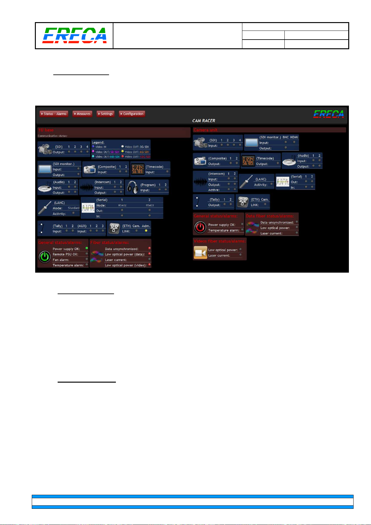
Note that the screen is splitted in two parts, with basestation on the left and camera unit on the right.
Each sub page has its own set of status (dark blue groups) and its own set of alarms (dark red groups).
3.2.1 SIGNAL ACTIVITY
The homepage displays the status of each signal transmitted by the unit, the information reflected the unit
webpage is the same point of view as what happen on this unit connectors.
The signals are grouped in category easily recognizable thanks to the pictograms attached to each
category.
The video section is more detailed with the detected data rate colored indication Datarate is only recognized
on receiver’s channels.
3.2.2 ALARMS DISPLAY
The unit global technical status / alarm are summarized in the 3 lower categories:
•
Power supply alarms (Power good status, internal temperature over 60°C and fan defective
indication).
•
Data Fiber alarms (Optical receiver unsynchronized, Optical power monitoring on the Main
and spare fiber, Defective laser on Data transmitter).
•
Video Fiber alarms (Optical power monitoring and defective laser on Video transmitter).
ERECA SAS 75 rue d'Orgemont, 95210 SAINT GRATIEN France Tel +33 1 39 89 76 23 www.ereca.fr
Page 20
MT STAR AG Indice : 1 18/10/2016
20 / 25
3.3 MEASURES PAGE
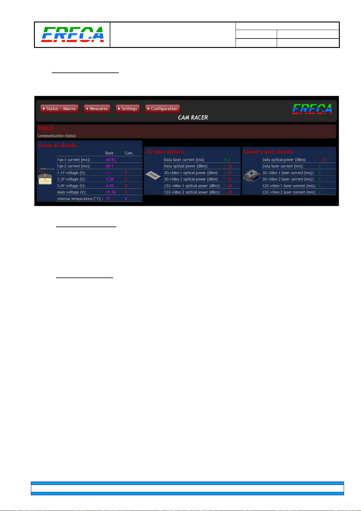
The "measures" page provides the detail of the product technical information.
MT CAM AG_v1.doc
3.3.1 GENERAL DETAILS
Provides detailed information of internal power supplies voltages / fan currents / temperature.
Figures are displayed in purple if all is OK and become red if the value is out of range (in this example the
camera module is not plugged on the basestation so its parameters are null displayed in red).
3.3.2 OPTICAL DETAILS
These two groups monitor the basestation and the camera unit optical state.
Each figure will change color if the alarm threshold is reached (60mA for the laser , < -18dBm for the 3G
optical receivers and < -13dBm for the 12G optical receivers).
The optical level below -18dBm (-13dBm) warns the user against a too high fiber attenuation or a dirty
connection, it does not mean that the signal will be lost (each receiver is tested to -20dBm(-15dBm)) but that
a connector cleaning or fiber trouble shoot has to be done on an asap basis.
The laser overcurrent is a preventive information, it indicates something wrong and that the unit need
service asap but should be still able to transmit data for the current event.
ERECA SAS 75 rue d'Orgemont, 95210 SAINT GRATIEN France Tel +33 1 39 89 76 23 www.ereca.fr
Page 21
MT STAR AG Indice : 1 18/10/2016
21 / 25
3.4 SETTINGS PAGE
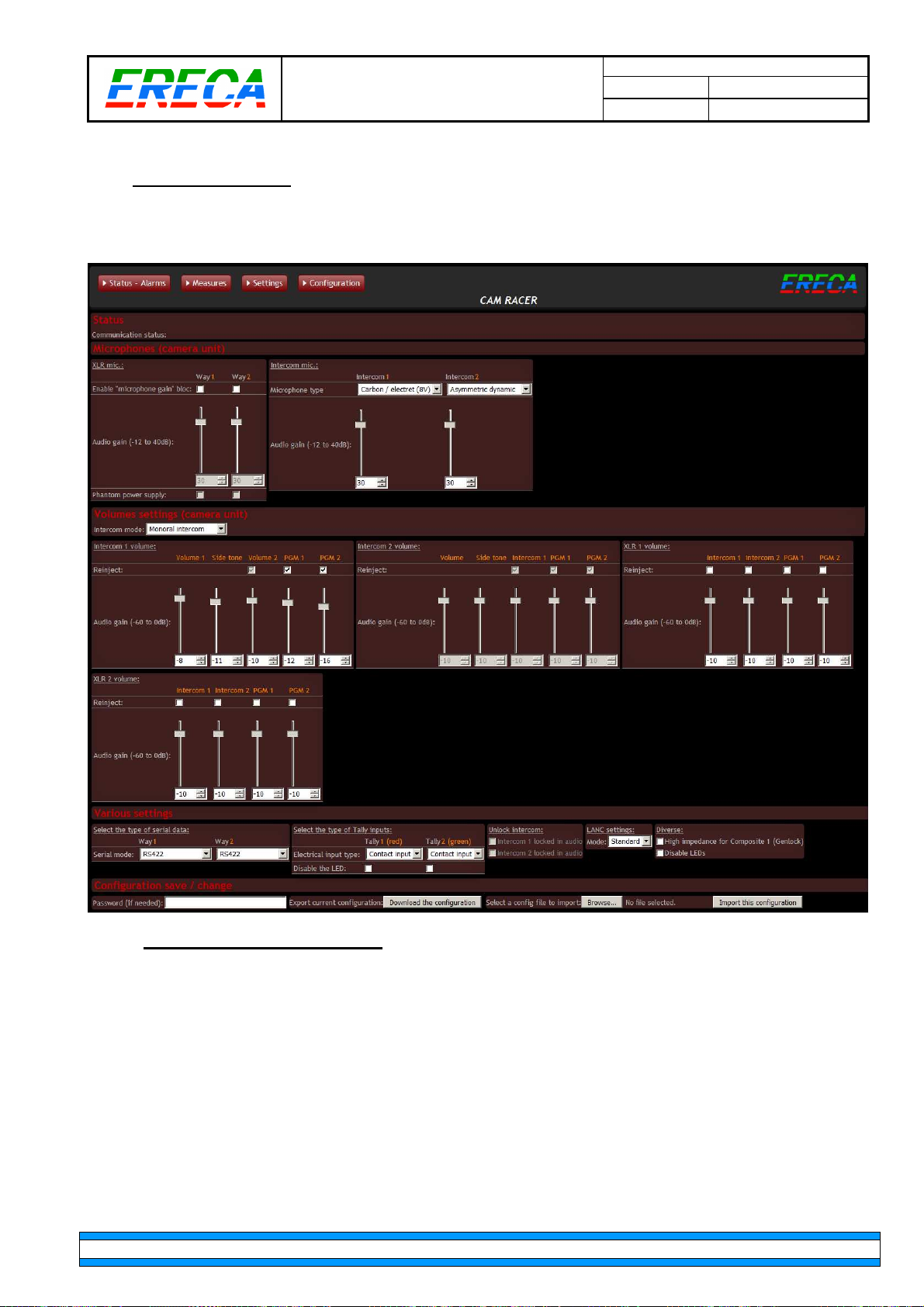
The following settings page groups all the possible settings or the transmission unit.
Settings are grouped by functions.
MT CAM AG_v1.doc
3.4.1 MICROPHONES SUB SECTION
The XLR/Mic group sets the mode and the gain of the 2 noble audio inputs on the camera unit.
Use can select Line or activate an internal Mic gain bloc with or without phantom power injection by ticking
the right boxes.
The Intercom Mic group sets the mic input gain and type from the list below:
•
Dynamic,
•
Asymmetric dynamic (most common),
•
Electret or Carbon (8 V / 470 Ohms polarization),
•
Fully static with 48V phantom power (CAUTION: Take care of your Headset MIC).
ERECA SAS 75 rue d'Orgemont, 95210 SAINT GRATIEN France Tel +33 1 39 89 76 23 www.ereca.fr
Page 22

MT CAM AG_v1.doc
MT STAR AG Indice : 1 18/10/2016
22 / 25
3.4.2 VOLUMES SETTINGS SUB SECTION
Please see audio mixer section (2.6) for detailed description.
3.4.3 VARIOUS SETTINGS SUB SECTION
This sub section groups all the single/simple configuration commands as:
•
Serial interface levels RS232/422/485.
•
Tally input levels and Led disable,
•
Intercom forgotten in talk position can be released here by ticking the right box,
•
Lanc protocol selection (Legacy / RCV-100) – Works only with RC-V100.
•
Turn Composite 1 input to high impedance,
•
Disable all the leds on the cam racer unit.
3.4.4 SAVE RECALL
User can Download / Browse / Import configuration from the corresponding buttons. Files are saved on the
memory of the user computer.
ERECA SAS 75 rue d'Orgemont, 95210 SAINT GRATIEN France Tel +33 1 39 89 76 23 www.ereca.fr
Page 23
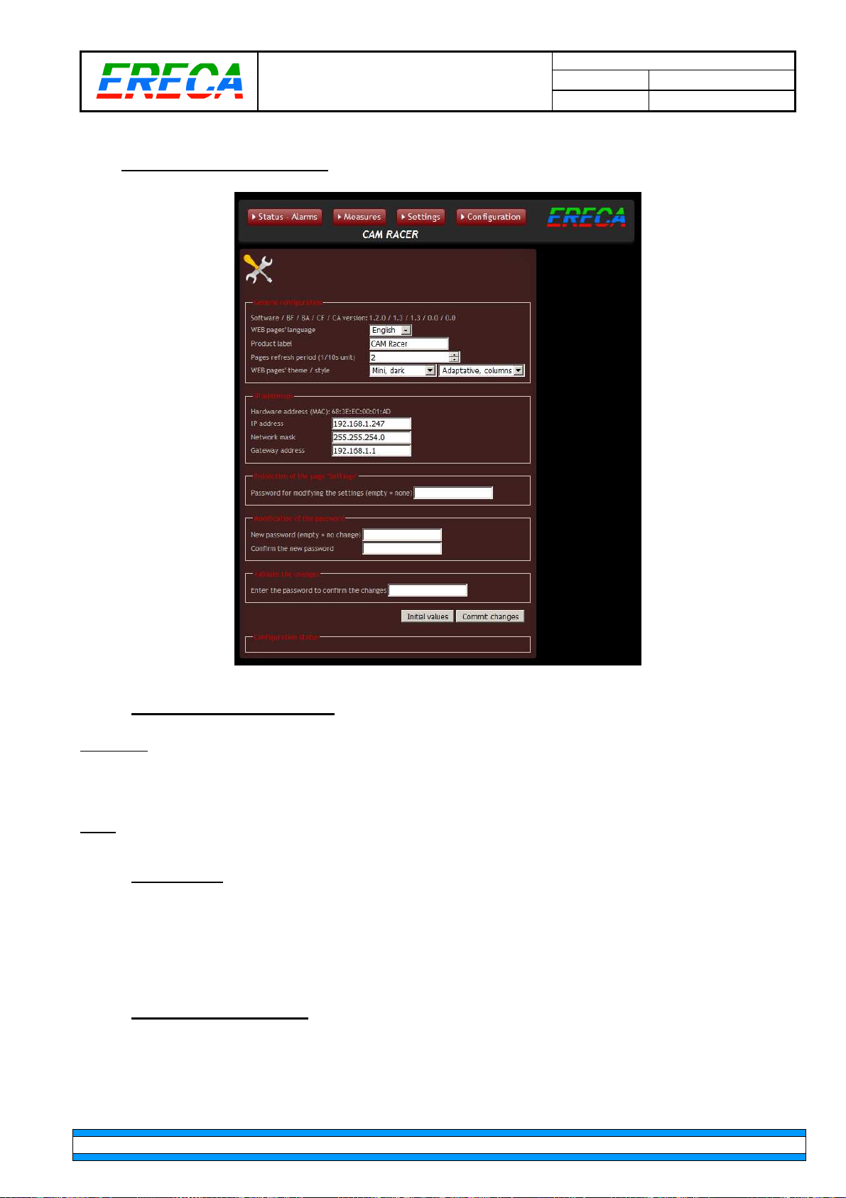
3.5 CONFIGURATION PAGE
MT CAM AG_v1.doc
MT STAR AG Indice : 1 18/10/2016
23 / 25
3.5.1 GENERAL CONFIGURATION
Important: For the stage racer product to validate changes done on this page, it’s mandatory to type in the
password (“ereca” as default) in the “validate the change section” and click on “commit change” button.
To revert to default type in “ereca” password and click on “initial values”.
Note: If IP add is lost, press RST switch at the rear of the unit for 5 seconds, the unit will revert to default
settings, or use the rotary button to read it on the Oled display.
3.5.2 IP ADDRESS
Setup the IP address of the unit, after validation with the password the unit instantaneously switches to the
new IP settings, an “internet” link route the user to the new address.
Default IP: 192.168.1.247 / NetMask 255.255.254.0.
3.5.3 SETTINGS PROTECTION
If the user wish to protect the “Settings” page setup, just type in the protection password chosen in the
“protection of the page settings” and validate with the commit changes procedure.
ERECA SAS 75 rue d'Orgemont, 95210 SAINT GRATIEN France Tel +33 1 39 89 76 23 www.ereca.fr
Page 24

MT CAM AG_v1.doc
MT STAR AG Indice : 1 18/10/2016
24 / 25
3.5.4 CHANGE PASSWORD
Simply type twice the new general password in the “Modification of password” section and validate with the
commit changes procedure.
ERECA SAS 75 rue d'Orgemont, 95210 SAINT GRATIEN France Tel +33 1 39 89 76 23 www.ereca.fr
Page 25
Optical
SDI
Video SD
to 12G
Composite
Video / GL
Analog Audio
Mic input
Timecode
LANC
Data
Ethernet
Intercom / Tal
ly
Power
section
Mechanical
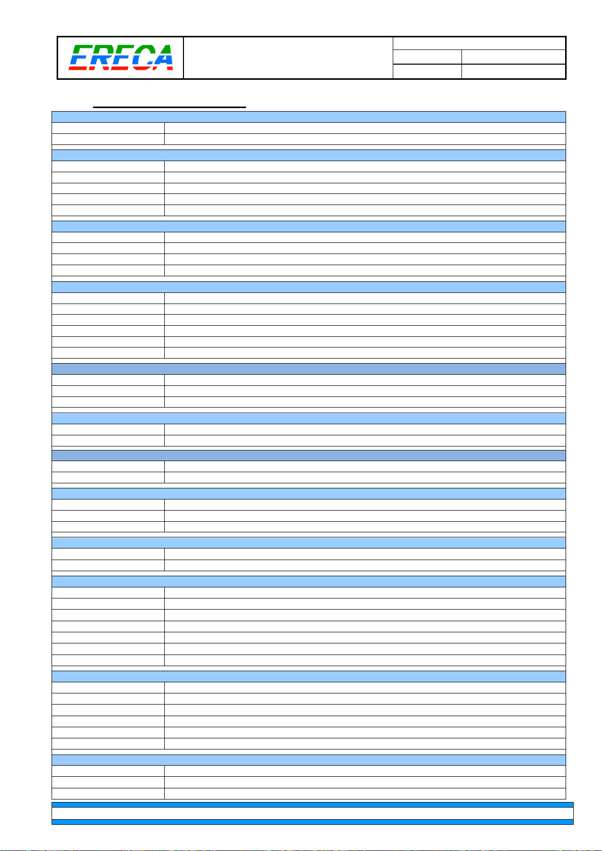
4 TECHNICAL SPECIFICATIONS
MT CAM AG_v1.doc
MT STAR AG Indice : 1 18/10/2016
25 / 25
Dynamic range:
Connector:
Connector:
Impedance:
Standard:
Amplitude:
Return loss:
Number, connector:
Standard:
Impedance:
Performance:
Number, connector:
Impedance:
Amplitude:
Bandwidth:
Distortion:
Signal to noise ratio:
Input:
Mic input, Gain:
Phantom power:
Number, connector
Impedance, Connector:
4
Number, connector
Protocol
15 dB for control and 3G signals, 10dB for 12G channels.
LEMO 3K (EDW / FXW) or NEUTRIK OpticalCon DUO.
3G certified BNC and 12G certified BNC.
75 Ω.
SDI, ASI, HD, 3G on basic model. SDI, HD, 3G, 6G, 12G with optional 12G channels board.
Input: cable equalization on all channels including 12G, Output: 800 mV pp / reclocked.
Better than: - 15 dB for 0 to 1.5 Ghz, - 10 dB for 1,5G to 3G, -6dB for 3G to 12G.
2 from basestation to camera, 2 BNC.
Composite video, Black Burst, Tri-level (Bi / Tri level auto sense).
75 Ω.
BW > 5.8 MHz at +/- 0.2 dB, DgDp < 1%, < 1°, Group delay < 10 ns, SNR > 67 dB (CCIR567).
2 bidirectional channels, XLR 5pins on camera unit, XLR 3pins on basestation.
Input: 10 KΩ differential (non floating), Output: 20 Ω differential (non floating).
+ 18 dBm maximium.
50 Hz to 15 KHz at +/- 0.5dB, (20 Hz to 20 KHz at -3 dB).
0.05% at 1Khz / 0 dBm.
90dB, "A" weighted.
Microphone input gain block on the camera unit.
From -12 to 40 dB, Tunable by 1 dB steps, Totally bypassable.
48 volts switchable, Source Impedance 6.8 KΩ.
1 from basestation to camera unit , BNC.
75 Ω, BNC.
1 bidirectionnal, Jack2.5mm.
Standard LANC or RC-V100 remote protocol (5V open collector signaling).
Number, connector:
Protocols:
Data rate:
Number, connector:
Protocols:
Number:
Tally output:
Tally input:
Camera Intercom I/O
Base st. Intercom I/O
Talk command
Connector
Camera unit:
Camera power capacity
Regulator option
Battery plates
Basestation unit:
Mains source base:
2 bidirectional channel, RJ 45 for Channel 1, Hirose 12 for channel 2.
RS485, RS422, RS232.
0 to 500 Kbd/s.
1 channel, RJ 45.
10 or 100 Mb/s, Full or Half-duplex (Auto sense), MDI or MDI-X (Auto sense).
2 Tally, 2 Intercom.
Relay (dry contact) shared with serial RJ45 (red) and Hirose 12 (green). Red/Green LED
Contact or Voltage input. Shared on intercom D-SUB 25 pins with standard CCU pinout.
Any type of Headset Mic (Dynamic, Electret; Static ) and Earpice impedance (20 to 600 Ohms)
Line levels for Intercom and program input.
Pushbutton on cam unit, PTT input on RJ45 for pocket PTT switch. (Talk latch release on basestation).
XLR 5 pins (intcom1), Hirose 12 pin (intcom2), Standard D SUB 25 pins on base (Tally, Intcom, Pgm).
7 Watts for 2x3G basic device + Additional 3W for dual 12G channel option.
14.4V, 140W continuous, temporary unlimited with automatic battery backup.
8.4Volts 4Amps output for Canon devices on dedicated D-TAP.
V-Lock or Anton Bauer (under development).
10 VA for the basestation (Additionally up to 200VA for remote power source).
From 90 to 260 VAC / 47 to 63 Hz.
Camera unit:
Basestation:
Operating Temp range:
ERECA SAS 75 rue d'Orgemont, 95210 SAINT GRATIEN France Tel +33 1 39 89 76 23 www.ereca.fr
155 * 145 * 44mm excluding connectors & plates (Add 13mm for power converter), weight 1400 grams.
1 RU 19” rack, depth 250mm excluding connectors, weight 3000 grams.
From -20 to + 60°C. (Avoiding direct sun exposition).
 Loading...