

Page 1
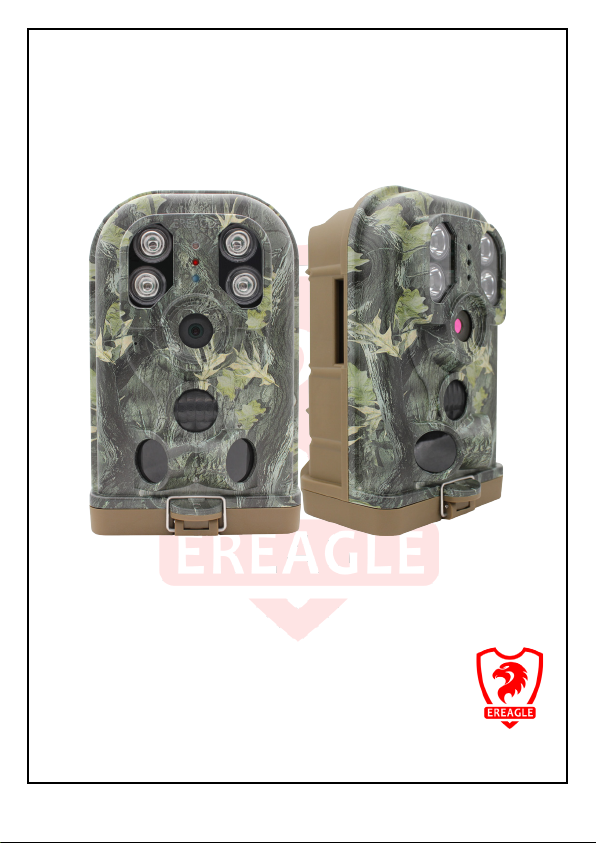
User Manual
E1 Series
V112 ED-E1S-TM-01
Intelligent Trail Camera
12M, 1080P/30FPS, IP68, MMS /SMTP
Technology Innovation from EREAGLE
Thank you for purchasing our camera series products.
Before attempting to connect or operate this product, please read these
instructions carefully and keep this manual for future use.
Page 2
CAUTION
4
1. General Information
5
1.1. Product introduction
5
1.2. Feature
1.3. Graphic Illustration
2. Installation and location selection
3. Quick start
3.5. Download the Camera manual and Setup APP
11
3.6. Guide for the setup menu (in the camera)
12
4. Advanced Operation
15
4.1. Mode Description
15
4.2. Set camera on PC
16
4.3. Menu operation method
18
4.4. Shooting mode selection
18
4.5. Audio settings
19
4.6. Trigger alarm settings
4.7. Time and date
4.8. Time lapse
4.9. Camera Name
------------------ CATALOG ------------------
2.1. Bandage installation
2.2. Seal the bottom cover 9
2.3. Installation location selection 9
3.1. Battery installation 10
3.2. SD/TF Card installation 10
3.3. SIM Card installation 11
3.4. Enter Test mode and ON mode 11
9
10
5
6
9
4.10. Night lighting 20
4.11. Telecommunications 21
4.12. User Interface Stamp 22
- 2 -
19
19
20
20
Page 3

4.15. SD Card Cycle
23
4.16. Default Setup
23
4.17. Software Version Information
23
4.18. View, Delete the image and video
23
4.19. Auto power off
24
4.20. Laser positioning
24
4.21. Quick setting Photo and video
24
4.22. Low power alert
25
4.22. Software version updates
5. Other operation
5.1. Connection of external power
5.2. USB cable use
6. Warranty Information
7. Appendix Technical Specification
8. Packing list
9. Dimension
4.13. Password 22
4.14. SD/TF Card Format 23
5.3. TV Video Cable Use 27
5.4. TF card capacity data sheet 28
29
30
32
33
RoHS 34
25
26
26
26
- 3 -
Page 4
This equipment has been tested and found to comply with limits for a Class A digital
device, pursuant to part 15 of the FCC Rules. These limits are designed to provide
reasonable protection against harmful interference when the equipment is operated in a
commercial environment.
WARNING: Changes or modifications not expressly approved by the manufacturer
could void the user's authority to operate the equipment.
WARNING: To prevent electric shock and risk of fire hazards:
● Do NOT use power sources other than that specified.
Termly Inspection
Please refer inspection to accredited service person.
Do NOT install on weak upholder
Install on strong enough upholder, or may fall off or cause other hazards.
Keep off inflammable gas or liquid
May cause risk of fire hazards or else.
Do not exceed the limit of temperatures using the camera
The normally working temperature of the camera is -30°C~+70°C, once used in high temperature
conditions, please pay attention to ventilation.
Do not let the camera suffered shock
will lead to the camera failure.
Do not let the camera is radiated By the radioactive substances
If the camera is exposure to the radioactive environment, will damage the CMOS of the camera
Do not remove camera privately
Will lead to damage the internal structure or components, or risk of fire, electric shock, or the other
dangerous.
Please install the batteries with the correct polarity
Do not use the old and new batteries together
Will lead the camera with malfunction and the battery leakage.
- 4 -
Page 5

1. General Information
1.1. Product introduction
The Ereagle tr ail camera is a smart IR surveillance waterproof device. It can take high quality photo (up
to 12M pixels(Interpolated), real 5M pixels and video automatically with the preset parameter by customer,
triggered by any movement of the human being and animal by the highly sensitive PIR sensor. The double
D/N filter IR cut switcher helps while the ray of light is not good and then take clearer photos and videos.
There is one 2.0” color LCD display screen and sound recorder, it can check whether the photo area is
reasonable by inner laser light and check photo and video at any time.
With it’s high waterproof grade of IP68, Ereagle trail camera can be used in outdoor.
The model Ere-E1S can automatically send pictures or text messages to the specified user’s phone or
mailbox. Users can also set the maximum number of messages sent per day to control the message cost.
1.2. Feature
Built-in 2G GSM wireless image transmission function, SMS / MMS / E-mail(SSL) are optional.
Support daily report SMS notification, Support low-power SMS notification.
Support four frequency band quad-band: 850/900/1800 / 1900mhz.
With 1/3” high definition 5MP image sensor, Low illumination:0.1Lux (LED off)
7.45mm fixed lens. (H FOV=50°, F3.0)
Photo definition can be optional with 12M/8M/5M/3M/2M/1M, Support shooting maximum 5 photos
1080P/30fps full HD video recording, 1080P/720P/480P is optional
The G. 726 audio compression method, to make real-time monitoring
Support both photo and video mode, auto make video after the photo shooting, more convenient
observation at the scene.
With double infrared detectors, Pre detection and capture detection work together to make detection
range wider and capture more accurate.
Multiple PIR sensor design make the sensing distance 20 m / 65.62 feet, induction higher sensitivity,
more accurat e.
PIR shortest trigger time can reach: 0.8 seconds.
PIR main induction angle 45 degrees, on both sides of the sensor PIR Angle is 100degrees.
Precision processing structure, waterproof level of IP68 (dust tight/flooding); Camouflage design.
Support stamp of device name, time, temperature and moon phase.
Support time taking pictures function, can set a day in three periods and time intervals, and can choose
week repeat.
Support capture at night, Invisible infrared light, makes the effective distance of 20 meters; Light
intensity is adjustable.
Built-in high-definition infrared cut, makes the shooting photo more real and gorgeous, switch more
stable and reliable.
4 x AA / 8 x AA / 12 x AA group of alkaline battery can be optional, maximum standby working time can
be up to ten months.
Support 1.2V / 1.5V / 3.2V / 3.7V various specifications rechargeable batteries.
Support electronic protection against reverse battery, so as not to damage the camera.
2.0” high resolution color LCD display screen; Adopt multi-function remote button, control more
convenient and quickly.
Support USB data connection and PC fast parameter settings.
Support external power supply or solar power, to provide longer working hours.
Support dismantling chains, protection lock and password protection function, to protect the camera
sa fet y.
Support low power alert.
Support TF card with maximum capacity of 64G.
Support the laser alignment, to make more convenient installation.
- 5 -
Page 6
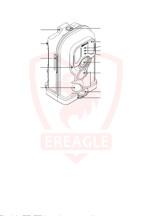
1.3. Graphic Illustration
St rap Hole
IR LED
Le ns
Side P I R
Lock Hol e
S afe-Gu ard
L oc k Hole
A nt iskid
Mai n PIR
Ante nna Port
Sta tus LED
La se r Pointe r
Nigh t Sens or
Microphon e
Sea l ing B u ck le
1
.Lens
It is used for collecting the video and
image information of the detect target.
.Main PIR
2
It is used for inducting the moving objects
of the heat resource, then trigger and take
photos and video.
.Side PIR
3
Induce the border of heat resource.
.Microphone
4
Used for collecting the sound information.
.Laser Pointer
5
For position adjusting during the camera
installation.
.IR LED
6
Provide light for night shooting.
.Status LED
7
The hints of camera state and trigger.
8
.Light Sensor
Induction of light intensity, trigger the
camera into the day and night mode.
.Lock Hole
9
Lock the bottom cover, waterproof,
dust-proof. Prevent malicious removal.
10.Safe-Guard Lock Hole
Anti-theft device
.Antiskid
11
12
.Strap Hole
13
.Antenna Port
- 6 -
Page 7
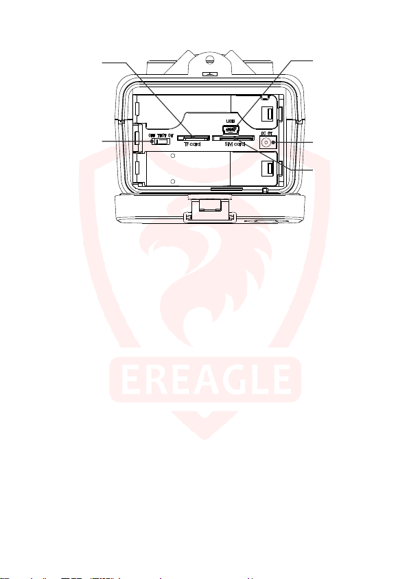
TF Por t
USB Port
DC Port
Test/O N/OFF
Swi tc hes
SIM Port
14
.DC Part.
Used for external power supply, support DC 6V/2A power supply connection.
.USB Part
15
connect PC with USB cable.
.TF Part
16
To store video, image and data information.
.SIM Part
17
GSM communication card for transmitting or receiving text image information.
.TEST/ON/OFF Switches
18
Include Test mode, ON mode and OFF mode.
7
Page 8
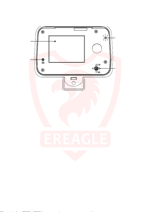
Spe ak er
Men u Butto n
LCD Di sp lay
Vi ew Bu tto n
19
.LCD Display
For viewing video and image information and menu display.
.View Button
20
For viewing video and image information.
.Menu Button
21
For menu setting operation.
.Speaker
22
Play video sound.
8
Page 9
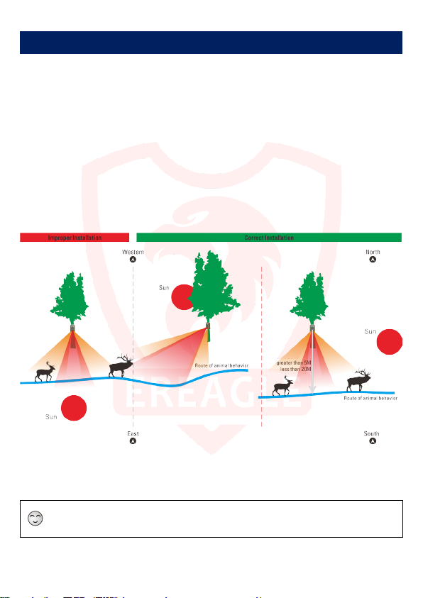
2. Installation and location selection
2.1. Bandage installation
The camera is designed with a bandage hole for fixing the camera.
Thread the bandage from one side to another side of the hole, then fix the bandage in a solid trunk of the
tree, you can adjust the tension of bandage to adjust the camera position, tighten it after the adjustment.
2.2. Seal the bottom cover
Camera is sealed with 20mm high-strength elastic metal buckle, after installation and testing, please
make sure the bottom cover locked firmly to ensure that the camera with good waterproof, dustproof
performance.
Note that the metal buckle should be fixed within raised part and then locked firmly.
2.3. Installation location selection
Selection of camera location see below.
After selecting shooting place, fix the camera on the thick trunk with the bandage and adjust the
induction angle.
When finishing, shake the camera to see whether firm enough.
If fixed in the wall, you need to install the matched mounting bracket by standard British screw holes.
The camera is installed on a relatively thick tree or on the wall, To keep the proper height when fixed, so that
it can shoot the corresponding action target.
Avoid direct sunlight on camera lens.
9
Page 10
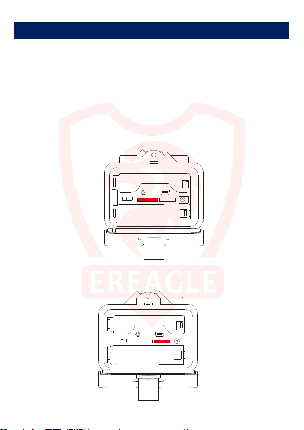
TF CARD SIM CARD
USBTV
OFF TEST ON
DC 6V
TF CARD SIM CARD
USBTV
OFF TEST ON
DC 6V
3. Quick start
According to the instruction of above parts, operate the corresponding button, then you can complete
the basic operation.
3.1. Battery installation
Prepare 4 x AA / 8 x AA / 12 x AA group of alkaline batteries, a group needs at least 4 x AA alkaline
batteries.
Open the camera bottom cover, unlock the battery cover plate, to put the alkaline batteries in the battery
box according to the polarity marked on the battery cover correctly , then close the battery cover.
3.2. TF Card installation
After the battery is installation, insert the TF card to the right direction, make sure the TF card is
unlocked before installation. (We recommend using C10 standard Sandisk brand TF card)
3.3. SIM Card installation
After TF card is installed, insert the SIM card correctly according to the specified direction, support the
four bands: 850/900/1800 / 1900mhz.
10
Page 11
3.4. Enter Test mode and ON mode
There are three mode for the switch, OFF, TEST and ON mode.
:When the switch to the OFF position, the camera will be power off automatically.
OFF
:When the switch to the TEST position, the camera enters the preview test status, you can
TEST
manually start taking pictures, record videos, view photos and videos, set the parameters and so on.
With this mode, you can also test the induction area of the PIR: When fix the camera into this mode,
the user can walk slowly right in front of the camera from 3 to 20 meters. When the blue LED indicator
light flashes, means this location can be inducted by the main PIR. When red LED flashes, means this
position can be inducted by the side PIR.
There are three status under test mode: Preview status (on the LCD screen or TV screen, you can
see the curre nt camera image in f ront of the lens), Setting status (enter the parameter setting menu)
and Playback status (In the LCD screen or TV, you can see the images from the SD card). After turned
on with test mode, the camera automatically enters into preview status.
ON: also called automatic infrared shooting mode. When the switch to the ON position, the camera
enters On mode. When entering this mode, the system will wait about 10 seconds, at the same time
the red LED flashes, then goes out after that and goes into induction shooting state. After entering this
mode, the system will automatically shooting based on your setup parameters, when the person or
animal enters the monitoring area.
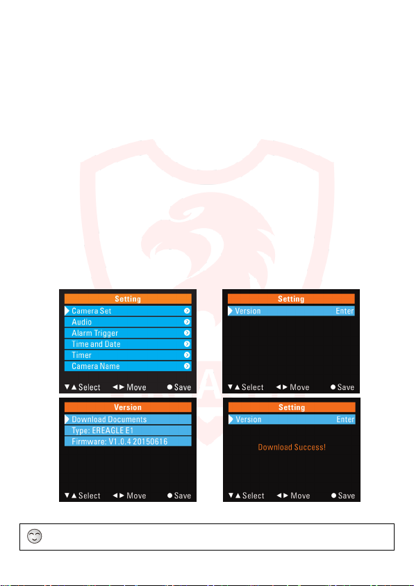
3.5. Download the Camera manual and Setup APP
Press“MENU” to set enter the setting menu.
Press “UP” and “DOWN” to move to Version setting, and press“MENU”to enter the sub-menu.
Press “UP” and “DOWN” to move to the Download Documents options, press“MENU ”to start
downloading .
"Download success" will appear on the screen. Files will be automatically saved in SD card.
The above is a simple operation. For mor e detailed instruction, Please refer to the instructi on at the later
Advanced Settings.
11
Page 12
Items
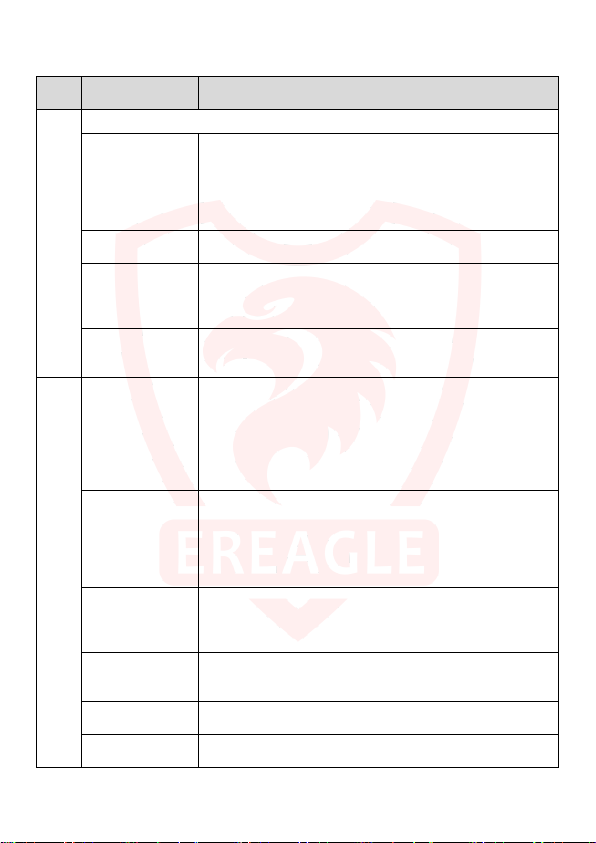
3.5. Guide for the setup menu (in the camera)
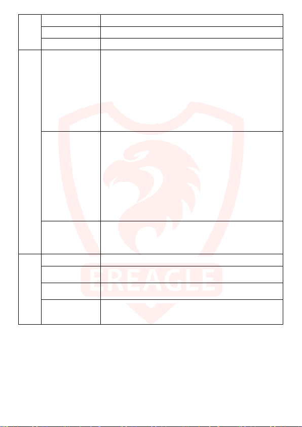
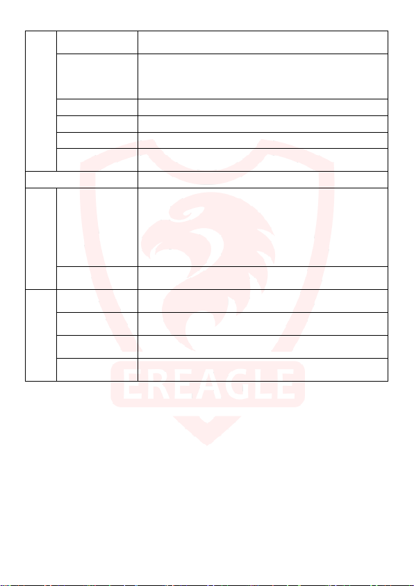
The following description is mainly for the use of menu parameters.
Main
Sub Items Function and Application
Select Network Operators
【OFF】: Turn off the remote communication function. In this mode all
MMS/SMTP Setting
Camera Set
Send Mode
MMS/SMTP
Parameter
Send Number
Daily Report
Mode
Image Size
Video Size
Shooting No.
Video Length
Max Shooting
communication related functions are invalid.
【MMS】: Trigger to send the picture to the user via MMS. Can send to up
to 3 mobile phone users and a mailbox user at the same time..
【GPRS】: Trigger to send pictures to users via email, support SSL
encryption. Can send to up to 3 mailbox users at the same time.
It is used to Setting MMS/SMTP related Parameter and receiver
information.
The setting is used to limit the maximum number of messages sent per
day, set to "0" means no limit, maximum limit of 255. By setting the limit
can effectively control the cost of sending information. The limit does not
affect the triggering of the photo, only limit the number of messages sent.
The setting is turned on, the user will receive a text message at 9:00 AM
every morning in time, in order to know the current state of the camera
(including power, signal, version, TF card information, etc. ).
Select the camera mode to suit different shooting situations and
application
【Camera】:Used only for scene that only take photos after triggering.
【Video】:Used only for scenes that require recording after triggering.
【CAM+Video】:Used for scenes both need to take pictures and video
after triggering. In this model, it takes picture first, and then makes
records.
You can select definition of the picture taken, the higher the definition,
more storage space it occupies. The user can select the appropriate
resolution according to the size of the SD/TF card
【12M】:4608×2592 Pixel; 【8M】:3624×2448 Pixel;
【5M】:2560×1920 Pixel; 【3M】:2048×1536 Pixel;
【2M】:1920×1080 Pixel; 【1M】:1280×720 Pixel;
Select the video resolution, the higher definition will occupy more storage
space.
【1080P】:1920×1080 / 30fps; 【720P/60】:1280×720 / 60fps
【720P/30】:1280×720 / 30fps; 【480P】:720×480 / 60fps
This parameter indicates that you can take multiple shots continually after
the trigger,the maximum shooting number can be 5.
1~5:The number of consecutive snapshots
Set the length of the recording, can set from 1 to 120 seconds, the
maximum length is 120 seconds.
Set the shooting limit per day, the maximum limit is 255 times, set to 0:
means no limit.
12
Page 13
accurate detection target
al input date and time, year, month, day, minute and second can be
Audio
Audio Record This setting is used to turn on or off sound while recording
Boot Sound Set whether the start beep is turned on or off.
Key Sound Set whether to turn on or off the key beep.
PIR Mode
Parameter PIR
Sensitivity
Interval
Time format Set the time display format. 12 hours (eg AM 8:00) / 24 hours (eg 15:30)
Time and Date
Date format
Setup time
Time Zone Settings
Select PIR trigger mode, you can use Main PIR trigger or Side PIR +
Main PIR trigger mode.
【Main PIR Trigger】: This is the most common trigger mode. In this
mode, only the Main PIR can trigger the shooting and the Side PIR is
disabled.
[Side PIR + Main PIR trigger]: This mode is mainly used to capture fast
speed of the heat source objects. In this mode, the Side PIR trigger will
pre-start the camera to speed up the boot speed; Then it captures
immediately when Main PIR triggers.
[OFF]: turn off the PIR trigger, PIR will stop working, no longer detect.
Select a different PIR trigger sensitivity.
【Auto】: automatically adjusts the PIR sensitivity according to the
change of ambient temperature. In this mode, it can adapt the different
working environments, and it triggers in high accuracy, low error
shooting.
【High】: for small temperature changes, small hot air flow environments,
detect of small mobile objects or long-range detection. At the same time
because of the high sensitivity, certain error shooting may happen.
【Medium】: Suitable for normal capture environment.
【Low】: Suitable for environment of closer detection distance and
The time interval between the trigger and the next trigger. Set from 1 to
59 seconds, 1 to 60 minutes.
This setting is mainly used to control the frequency of shooting, it will help
reduce the same scene of repeated shooting.
Set the date format. Available in three formats: 2008-12-23; 2008/12/23;
2008/23/12
Manu
adjusted.
Set the time zone in different countries to correct the time; usually set
time zone while setting the NTP.
When you set the time manually, you do not need to enter a time zone.
13
Page 14
Timer
Timer Set
Time Lapse
Time 1 Time period 1 setting per day. For example: 1: 20: 20 ~ 7: 30: 20
Time 2 Time period 2 settings per day.
Time 3 Time period 3 settings per day.
Repeat
Camera Name Used to set the camera name.
Night vision
Night vision mode
Light Level
User Interface
Camera Name
Stamp
Shooting Date
Temperature
Moon Phase
This option controls whether shooting is triggered on or off for the set time
period.
Turns on or off interval timer. When this setting is turned on, the PIR will
stop triggering.
[Interval shooting time]: Take pictures by the time it set, not effect by PIR
trigger effect . Setting range: 00: 00: 00 to 23:59 :59
Select the days per week according to the time set above to shoot for
trigger shooting. multi-select
【Auto】: the camera will automatically recognize the day or night,
automatically select Off / On fill light and switch the image mode color /
black and white.
【Day】: The camera has been kept in daytime color image mode, fill light
is not enabled.
【Night】: The camera has been in the night black and white image mode,
fill light is enabled.
【Standard】: The IR LED current to 900mA.
【Plus】: The IR LED curr ent to 1300mA.
Used to turn on / off whether name information is displayed on pictures
and videos
Used to turn on / off whether time information is displayed on pictures and
videos.
Used to turn on / off whether temperature information is displayed on
pictures and videos
Used to turn on / off whether moon phase information is displayed on
pictures and videos
14
Page 15
Password
SD Card Format
SD Card Cycle
Default
Version
Download
Documents
Type Displays the camera model information.
Firmware Displays the software information for this camera.
When Password is on, the camera needs to input a password to enter in
test mode.
After opening the password, the camera itself has a default password, in
order to ensure security, it is recommended that users re-enter the new
password and password confirmation.
Used to format the SD card, the operation will automatically clear all the
SD card images and video data.
When this sett ing is on, new pictures or videos will automatically
overwrite older pictures and videos when the SD card has insufficient
storage space.
This operation will restore all the camera parameters to the factory
default settings. It is recommended that you perform this operation if the
camera is not working properly.
The camera will automatically download the camera's corresponding
manual, software and other files to the SD card, the user can copy the
files to the computer from the SD card.
15
Page 16
4. Advanced Operation
4.1. Mode Description
Test Mode
Enter this mode, the red light flashes, the camera automatically enter the real-time preview interface.
After the system automatically detects with normal status the indicator lights will turn off.
After a few seconds, the PIR status can be observed by the color of the flashing indicator. Red indicates
the side PIR is triggered and blue indicates the main PIR is triggered.
If the camera is password protected, you need to input password to enter the preview interface.
Following Operation can be performed in this mode:
View video and images: You can enter by pressing the button to view the screen the shooting screen
detail.
Parameter settings: Enter the menu button to set parameters.
Laser positioning: in this mode press the Left direction button to open the laser alignment, to check
the installation position of the camera.
Shooting test: Press Right direction button to take images and video in test mode.
Quick Setup: Press UP and Down direction button to quickly switch camera mode and video mode.
PIR detection hint: Support PIR detection indication in this mode.
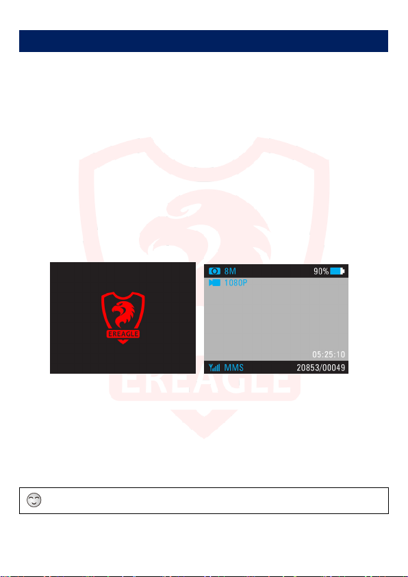
Boot screen Real Time Screen
Shooting mode and definition are displayed at the upper left corner of the screen.
Upper right corner it shows the battery level; when the battery is less than 20%, the icon turns red.
The screen below displays the status of the SD card; Without SD card, the icon is displayed in red and
will give alarm. The bottom right display total photos quantity, the taken photo quantity and the remaining
video recording time.
In this mode the camera does not take photos f or detected heat source object, only LED indicator hints.
16
Page 17
ON Mode
Enter this mode, the indicator light starts blinking .Then the system starts the internal self-test and
enters a low-power consumption standby state after that, the LED turns off.
In this mode the camera will enter the normal working condition, starting PIR detecting.
When the side PIR is triggered, the camera starts pre-starting,not shooting photos; Only when the PIR is
triggered, can the camera automatically and quickly shoot and store the images.
In order not to affect the detected heat source obj ect, in this mode the camera would be no li ght hint, also
no visible light and noise.
4.2. Set camera on PC
For multi camera parameter settings rapidly, users not only can set through its own menu on the camera,
but also can set parameters via PC setting software.
PC-side software is stored in the camera menu, can be downloaded through the menu operation to the
SD card. The latest updates software are available on the EREAGLE website.
Setting steps:
1. First of all, click "Download documents" in the camera menu “version” option, the camera manual and
PC-side software will be automatically stored in the SD / TF card. PC-side software contains "Set APP",
respectively for camera parameters and communication parameter settings.
2. Use the USB cable to connect the camera to the PC, find the appropriate software in the SD card on
the PC and open it, then install it.
3. Open the settings software, select the product model, select the storage location for the camera in the
SD card root directory.
4. Set the corresponding camera parameters and communication parameters according to your need.
5. After setting, click to generate the configuration file, the parameter configuration file will be
automatically stored in the camera SD card.
6. Disconnect the USB cable, restart the camera, the parameter settings complete.
The copy of Generated configuration files t o the SD card is still valid.
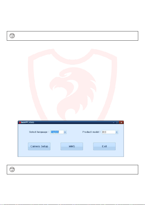
Language and model selection interface
17
Page 18
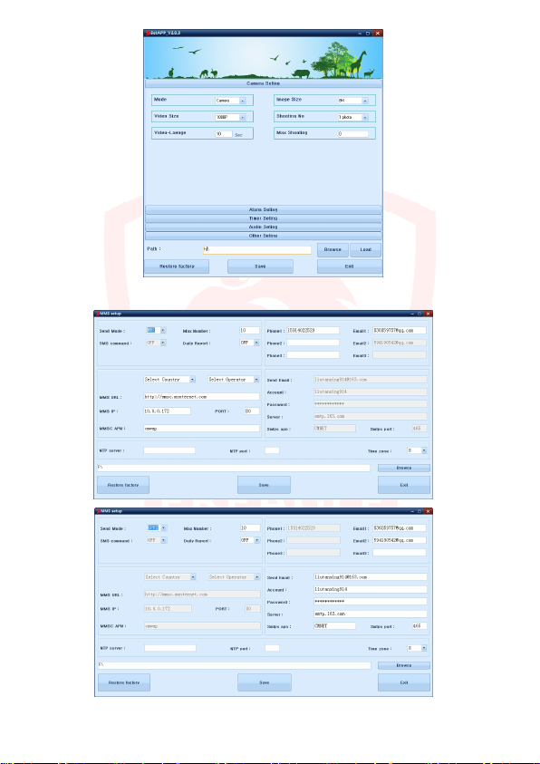
General parameter setting interface
MMS setting in terface
18
Page 19
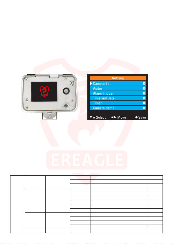
4.3. Menu operation method
Users can enter the menu and set parameters in the camera test mode; Alternatively, use PC-side
software for par ameter setting s.
Setting method:
1.Press the "MENU" button to pop up the setup menu.
2.Press "UP" and "DOWN" to move the cursor to select the corresponding option or parameter. Press
"MENU" or "RIGHT" key to enter the submenu or save the setting.
3.Press "LEFT" key t o return to the previous menu. Press "VIEW" key to save and exit the menu.
4.Press "LEFT" and "RIGHT" to select the input position, press "UP" and "DOWN" to select the number to
be input. Press "MENU" or "VIEW" to save and exit the menu.
5.Press the "LEFT" and "RIGHT" keys to move the cursor up and down while pressing the "UP" and
"DOWN" keys to enter the current character. Press the "VIEW" key to save and exit the menu.
4.4. Shooting mode selection
The camera supports 3 shooting modes, camera mode, video mode, camera + video mode.
Image parameters: User can choose the size of shooting pictures, continuous shooting number and
other parameters.
Video parameters: User can set the recording video definition, maximally 1080P/30FPS. You can also
set the video length.
Shooting Limit: User can control the shooting numbers per day by this setting, to reduce the power
consumption.
Mode Single selection
Image size Single selection
Camera Set
Video Size Single selection
Shooting No. Number 1~5 number of photos taken continuously 1
Button Menu
Camera camera only default
Video video only
Camera+Video Camera first, video second
12M 4608×2592
8M 3624×2448 default
5M 2560×1920
3M 2048×1536
2M 1920×1080
1M 1280×720
1080P 1920×1080 default
720P/60 1280×720
720P/30 1280×720
480P 720×480
19
Page 20
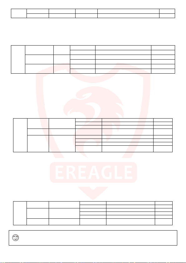
MM/DD/YYYY
11/6/2014
default
Video Length time 1~120s Video recording length of time, unit: second 10s
Max Shooting Number 0~255 Limit the number of daily shooting, 0 means no limit. 0
4.5. Audio settings
This function is used to for sound recording, turn on and off for button and power-on tone.
Audio Record
Audio
Boot Sound
Key Sound
4.6. Trigger alarm settings
Our camera inclu des pre-sensor PIR and shooting PIR.When the heat source moves the object into the
PIR pre-induction area, the camera immediately enters the start-up state; when the shooting PIR is triggered,
the camera quickly shoot. This method can be more accurately capture the target object.
Users can adjust the trigger interval and induction sensitivity according to the frequency of animal
activity, this can prevent repeated capture and get the more accurate data.
PIR Mode Single selection
Sensitivity Single selection Auto
Alarm
trigger
Interval Number
4.7. Time and date
Set time and date, to be local time synchronization, in order to accurately capture the target activity time.
So before use the camera, please set the time and date according to local accurate time and date.
Manual setting: The user can directly set the date and time in the menu. You can also set the date and
time display format.
Auto Acquisition Time & Date: The camera automatically obtains the time and date via the Internet
after each start. This function needs to set NTP parameters.
Time Format Single selection
Time
and
Date Format Single selection
Date
Setup Time date and time
Automatic acquisition time and date is o nly for mms camera ERE-E1S
The date and time set manually will be los t when the battery taken out for 20 seconds.
ON Open to record audio and video Sync default
Single
selection
OFF OFF
ON Open the boot sound default
Single
selection
OFF OFF
ON Open the buttons hint sound default
Single
selection
OFF OFF
Main PIR Only open Main PIR
Main&Side PIR Open Main and side PIR default
OFF All OFF
Low lowest
Normal normal
High highest
0sec-59min
12hours display: 6:42:54pm
24hours display:18:42:54 default
YYYY-MM-DD 2014-11-6
DD/MM/YYYY 6/11/2014
2014-11-6
18:42:54
According to the environmental
temperature automatic adjustment
the interval of next trigger after the
previous trigger.
If you need to manually set the date
and time, please set Auto off.
default
One min
20
Page 21
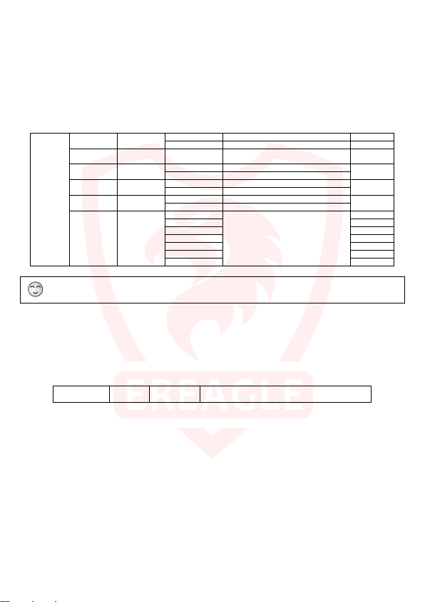
OFF
Close timer function
default
00:00:00
start time
00:00:00
start time
00:00:00
start time
Monday
√
Wednesday
√
Friday
√
Sunday
√
4.8. Time lapse
This feature allows the camera automatically record images or videos at specified time intervals for a
specified number of days and time periods. You can set three time periods per day and weekly repeat.
Timed Trigger Shooting: Users can set the time period to work every day after the timer shooting is
started. Up to three time slots can be set per day, and week repeat can be selected. This setting will trigger
and shooting only within the set time period.
Automatic timer shooting: In addition to setting the time period, you also need to open the shooting
interval and set the interval time. In this setting, the camera will automatically take the image according to the
shooting interval
timer
Time Lapse Time 0~60min
Timer1 Time interval
Timer2 Time interval
Timer
Timer3 Time interval
Repeat
Single
selection
multiple
selection
When time lapse is ON, The interval can’t be set to “ 0”and PIR trigger is invalid.
4.9. Camera Name
This parameter is used to set the name of the camera, in order to accurately get the camera information.
The name will be stamped on the photo and video.
Setting the camera name can help to mark the camera installation position.
Camera Name character 24 characters I t is made up of Numbers, letters and characters.
ON Start timer function
If the timer lapse is 0, it is PIR induction
mode
00:00:00 end time
00:00:00 end time
00:00:00 end time
Tuesday √
Thursday √
Saturday √
The selected effect
21
Page 22
Auto
Auto detect day and night mode
Default
Night
Always on night mode
Select Network Operators
SMTP
Send by Email
sent per day. Bit 0 is not restricted.
OFF
Don’t send
Default
SMTPS Parameter
It is used to Setting SMTP related Parameter and receiver information.
OFF
Not support
Default
4.10. Night lighting
This setting helps to improve the effect of insufficient light illumination change at sunrise and sunset.
Correct setting of this parameter can improve the shooting effect. Here you can set the day/night automatic
switching, night mode or day mode. In night mode, you can also set the light level to control the photo
brightness.
We provide three different lighting source, the user can choose according to your need
940nm invisible infrared light source: high power invisible light source, ultra-low red exposure, night
vision distance can reach up to 30 meters.
850nm invisible infrared light source: high power invisible light source, visible red exposure, night
vision distance more than 40 meters.
650nm visible white light source: high-power white light source, visible white light, night vision
distance more than 30 meters.
Night Vision Mode Single selection
Night
Vision
Light Level Single selection
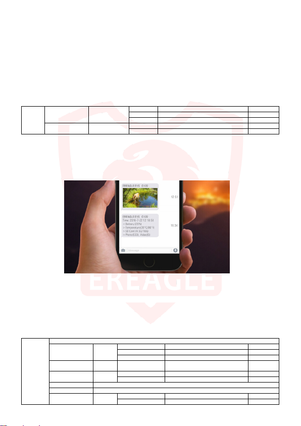
4.11. Telecommunications
When the PIR trigger shooting, the camera will automatically send SMS(short messages), MMS or
e-mail to the specified recipient. Our camera supports 3 different transmission methods.
Day Always on day mode
Standard The IR LED current to 900mA. Default
Plus The IR LED current to 130 0mA.
SMS: by sending text messages to the phone to notify the user.
MMS: by sending pictures to the phone to notify the user. You need to set the MMS parameters and
receiver information correctly.
GPRS: by sending pictures to the mailbox to notify the user. You need to set the SMTP parameters and
recipient information correctly.
Off: Close all communication related functions.
MMS Send by MMS
Send Mode
Send Number Digital 0~255
GSM
Setting
Daily Report
MMS Parameter It is used to Setting MMS related Parameter and receiver information.
Remote control
single
selection
OFF Turn off Communication Default
ON Send 1 daily report per day
single
selection
ON support
Single
selection
Limit the maximum number of messages
22
10
Page 23
Send Number: This function is mainly used to limit the number of messages sent by the camera every
day, which helps the user to control the cost. When the function is not set to 0, the interval is 10
minutes after each message is sent, and the message can not be sent again after the trigger shooting.
To prevent duplication of information and waste the cost.
Daily Report: The camera send the current data report of the camera to the specified user as a text
message every day. Including: power information, signal strength, temperature, storage capacity
information, the number of photos and videos.
MMS parameter: It is used to Setting MMS related Parameter and receiver information.
SMTP parameter: It is used to Setting SMTP related Parameter and receiver information.
Support SSL (Security socket Layer)
Remote control: not supported.
You must insert a valid SIM card when using the communication f unction.
When communication function is open, you must use the PC-side MMS Set software correctl y set the
relevant parameters in order to ensure cam era communication function works .
4.12. User Interface Stamp
Open the User Interface Stamp, the camera I D, Shooting Date, Temperature and Moon phase will be
displayed on the corresponding pictures taken.
User Interface
Stamp
Single selection
4.13. Password
Password protection is to increase security of camera par ameters. You should input the correct password
after you open the password protection function.
Password
Password Single selection
Password setup digit 1111 Make up of four numbers from 0 to 9 1111
4.14. TF Card Format
Format TF card。
This operation will lose the TF card, be careful.
ON Stamp Default
OFF No stamp
ON Open password protection
OFF Close password protection Default
23
Page 24
4.15. TF Card Cycle
After starting the TF Card Cycle, when TF card memory is full, the new recorded file will automatically
overwrite the old file.
4.16. Default Setup
For error of the parameter settings, the device will restore all settings to factory default settings.
This operation will make the camera autom atically shut down, need to restart the camera to restore the
factory Settings to take effect.
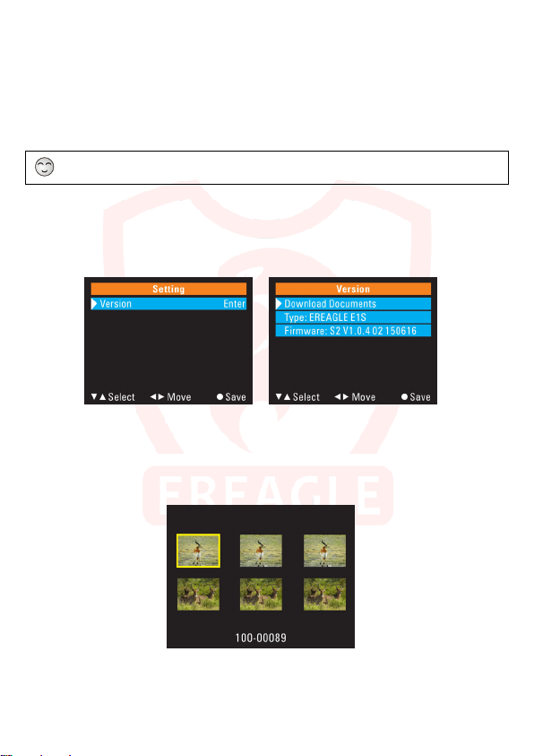
4.17. Software Version Information
Displays the camera's current firmware version number.
Camera data download, including instructions, PC-side software.
4.18. View, Delete the image and video
1.Press "VIEW" key to enter into view mode, the image and video thumbnails will be displayed on the
screen.
2.Choose "UP", "DOWN" and "LEFT" "RIGHT" keys, then press "MENU" to display the selected picture
or video in full screen.
3.In full screen, press the "LEFT" and "RIGHT" buttons to switch between the previous or next picture.
4.Press the "UP" key to return to the thumbnail display when full screen is displayed.
5.In full screen, press the "VIEW" button to display the deletion hunt. Press the ”LEFT” and “RIGHT” key
24
Page 25
to cancel delete or delete all options. Press the "MENU" key to confirm the operation.
6.Press the "MENU" button to enlarge the picture. You can press "UP", "DOWN", "LEFT" and "RIGHT"
keys to zoom in to view the picture details.
7.For videos, press "LEFT" and "RIGHT" key to control the slow-forward and fast-forward speed; Press
"DOWN" key to enter the reverse playback during playback, press "LEFT" and " RIGHT "key to
control the slow retreat and rewind speed, press the" UP "key to return to the thumbnail display.
4.19. Auto power off
When the user enters the test mode, the system will automatically power off without any operation within
120 S.
When the battery power is low, the camera will automatically power off.
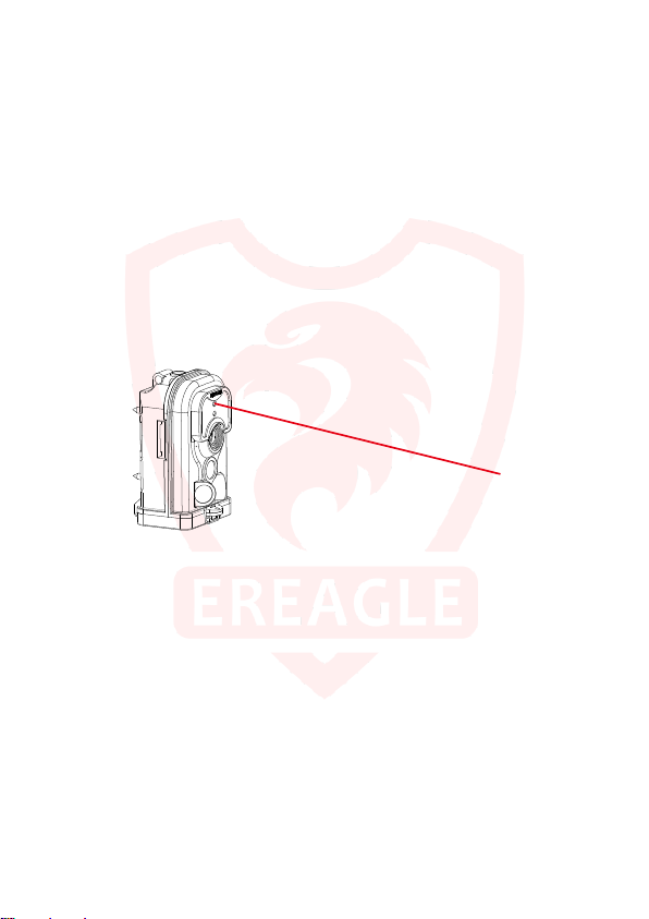
4.20. Laser positioning
When the user enters the test mode, press the "LEFT" button to turn on the laser light, then press the
"LEFT" button to close.
4.21. Quick setting Photo and video
When the user enters the test mode, press the "DOWN" button to switch to the camera mode, press
the "UP" button to switch to the video mode; press the "RIGHT" button to shoot.
4.22. Low power alert
If the camera battery power is less than 20%, when you enter the test interface,it will remind a low
power alert, the speaker will give alarm, battery icon turns red.
When the battery voltage is less than 4.2 V, the camera will automatically turn off.
4.23. Software version updates
User can view the current device model, code, and software version information in the version
information in the menu.
25
Page 26

If user wants to upgrade to the latest firmware version, you need to download the latest version of the
corresponding software upgrade package from our official website. Then extract the firmware. bin file in the
folder to the SD/TF card, insert the SD/TF card into the camera, and then switch to test mode. The camera
will automatically enter the upgrade program, turn off the camera and remove the SD/TF card after finishing,
and then change the SD/TF card without software upgrade package.
26
Page 27
Mi ni U SB
USB
5. Other operation
5.1. Connection of external power
There is an external power input interface at the bottom of the camera, you can use the external power
supply to charge, For example, solar battery, DC power supply, storage batteries and so on.
External power supply must be with DC 6V 2A
The bottom of the waterproof cover will be opened for external power supply, so the camera waterproof
grade will be reduced. The camera can’t be inverted installation, not even put in the water at this time.
When purchasing power supply, please note that the rated vo ltage, current, power connector and polarity.
Polarity of power interface
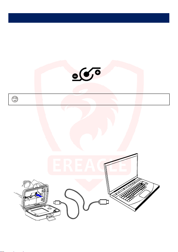
5.2 USB cable use
Connect the USB cable to the USB port on the PC, the PC will automatically recognize and install the
camera driver. When the recognition is complete, the mobile disk will appear in the computer. At this point the
user can copy file from the mobile disk and delete the file.
USB cable can be directly used for PC-side software to set the camera parameters.
27
Page 28

5.3. TV Video Cable Use
The video cable is used to connect the camera to a TV or monitor, making it easy to view pictures or
videos on a larger screen.
Plug the video RCA cable into the AV input of the TV or monitor, and connect the other end to the
camera AV connector.
Switch the TV or monitor signal input to AV mode and turn on the camera to display live video or view
pictures and videos on your TV.
Some cameras may need to be set to the TV mode to display the image.
Since the AV output quality is limited to 752 * 576 pixels, play the videos and pictures It will be lower than
the actual resolution while playing the video and phot os. So please don’t be mistaken for a lack of definition
of the camera.
28
Page 29
16G
14.9G
242分20秒
4G
3.725G
30分18秒
16G
14.9G
121分13秒
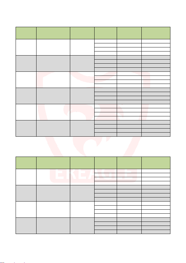
5.4. TF card capacity data sheet
Data sheet below will show you the capacity of different size of SD card.Then you will know which size of
SD card fit your need.
Resolution Pixel File size TF Card Capacity Picture amount
4G 3.725G 21100
1M 1280×720 176K
2M 1920×1080 384K
3M 2048×1536 512K
5M 2560×1920 896K
8M 3624×2448 1408K
12M 4608×2592 2176K
Resolution Pixel
480P
720P
720P60
1080P
720×480
60FPS
1280×720
30FPS
1280×720
60FPS
1920×1080
30FPS
Photo storage sheet
File size
/Sec
1024K
1024K
2048K
2048K
Video storage sheet
8G 7.45G 42350
16G 14.9G 84600
32G 29.8G 169300
4G 3.725G 9700
8G 7.45G 19400
16G 14.9G 38800
32G 29.8G 77600
4G 3.725G 7270
8G 7.45G 14500
16G 14.9G 29100
32G 29.8G 58200
4G 3.725G 4150
8G 7.45G 8300
16G 14.9G 16600
32G 29.8G 33200
4G 3.725G 2640
8G 7.45G 5290
16G 14.9G 10580
32G 29.8G 21160
4G 3.725G 1710
8G 7.45G 3420
16G 14.9G 6840
32G 29.8G 13690
TF Card Capacity Video length
4G 3.725G 60 分 36 秒
8G 7.45G 121 分 12 秒
32G 29.8G 485 分 2 秒
4G 3.725G 60 分 36 秒
8G 7.45G 121 分 12 秒
16G 14.9G 242 分 20 秒
32G 29.8G 485 分 2 秒
8G 7.45G 60 分 36 秒
16G 14.9G 121 分 13 秒
32G 29.8G 242 分 30 秒
4G 3.725G 30 分 18 秒
8G 7.45G 60 分 36 秒
32G 29.8G 242 分 30 秒
29
Page 30
Button doesn’t work
SD card can not be stored
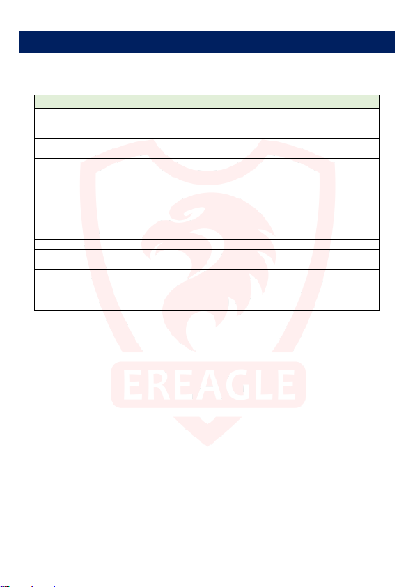
6. Warranty Information
If the camera malfunction, please see the following guide operation, if the malfunction can’t be solved,
please contact our local distributor.
General malfunction Self-test and solution
camera can’t be open
Always black and white image
The camera auto power off in
test mode
Abnormal display shows
Image out of focus
Image not displayed when TV
cable connect
Password lost
Can not receive SMS, MMS, or
mail
Check whether the batteries are installed cor rectly, the external power
whether open circuit or not, the SD card capac ity size meets requirement,
confirm the switch is not on OFF position.
Check the camera setting is correc t with the corresponding parameter’s
setting
Disconnect the power and restart the camera
Check whether the power supply is norm al, or long time no operation on
buttons
Check whether screen surface is clean, if under the cond ition of low and
high temperature, display screen shows m ay seem a bit dark, It can be
automatically recover in normal tem perature.
Whether there is a big shake when shooting camera, you can fix the
camera and see the effect.
Check whether the SD card is write prot ected or damaged
Check whether the TV cable connect is correc t or not, and check the TV
cable is damage or not.
Press “View” for 3 seconds and enter to set ne w password,then re-burning
software.
Check whether the parameters set by the PC soft ware are correct.
30
Page 31
Sensitivity:
0.005 Lux / F1.2 / 30IRE (LED off)
Lens:
7.45mm HD Fixed Lens (H FOV=50°;F=3.0)
Photo+Video:
View photo and video:
PIR Mode:
Main PIR / Main PIR & Side PIR / OFF
Trigger Interval:
Day/Night Mode:
:
:
:
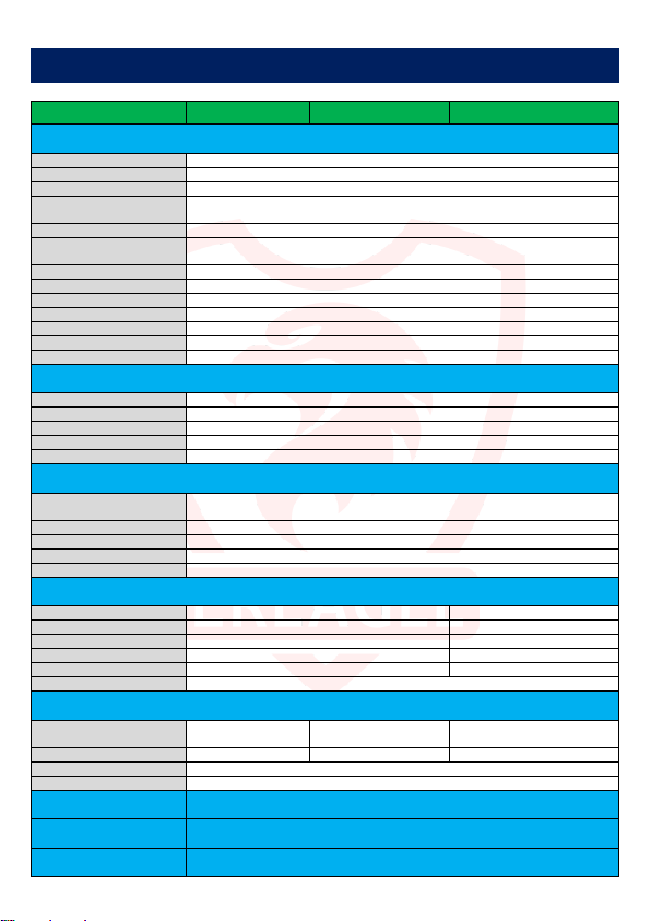
7. Appendix Technical Specification
Model ERE-E1B ERE-E1C ERE-E1S
Photo and video
Audio
PIR
GSM; Support SSL(Security Socket Layer)
Night Vision
User Interface Stamp
Image Sensor: 5Mega pixel 1/3 "HD color CMOS image sensor
Effective pixels: 2560×1920 / 4915.2K
Photo Definition:
Shooting No.: 1~5
Video Definition:
Video length: 1~120s
Trigger Time: < 0.8 Sec
Max-Shooting (Per Day) : Support, 0~255, 0 means no limit.
Display Screen: 2.0 "LCD Screen; definition: 960 × 480; 16.7M color
Microphone: 60dB High Sensitivity Sound Collection
Loudspeaker: 0.5W(8Ω) Hi-Fi Loudspeaker
Audio record: ON/OFF
Boot Sound: ON/OFF
Key Sound: ON/OFF
PIR Sensing Angle:
PIR Sensor Distance: 20M (at 25°C)
PIR Sensitivity: Auto / low / normal / high
Frequency band: No 850/900/1800/1900MHz
GSM Mode: No MMS/GPRS/OFF
MMS Photo Size: No 960x540
Send Number: No 0 to 255,0: No limit
Daily Report: No ON/OFF
Remote Control: No
Light source:
Night Vision Distance: 30M 30M 30M
Light Level: Standard(900mA) / Plus (1300mA)
Security Setting
Support 4 numbers, auto lock the camera if wrongly input the password for 6 times. Padlock installation.
Can set three period of time per day and weekly repetitions. Support automatic interval shooting and timer
Timer
4608×2592/3624X2448/2560×1920/2048×1536/ 1920×1080/1280×720
1920×1080/30 fps;1280×720/60 fps;1280×720/30 fps;
Support thumbnail,16 times enlargement, support video playing, support advanceX2/X4, retreat X2/X4
Side PIR: Left and right light beams form an angle of 140 °, left and right of the five zone, each zone 10 °
850nm or 940nm
2 / 4ea,IR H-LED
Shooting date, Moon phase, Camera ID and Temperature are optional: ON / OFF
12M/8M//5M/3M/2M/1M
720×480/30 fps
First photo, then video
Main PIR: 50 °, 8 zone, each zone 10 °
0-59sec,1-59min Programmable
650nm,2ea
white LED
Auto / Day / Night
Anti-theft lock hole
triggered shooting
31
850nm or 940nm
2 / 4ea,IR H-LED
Page 32
Storage, Power Supply and Power Consumption
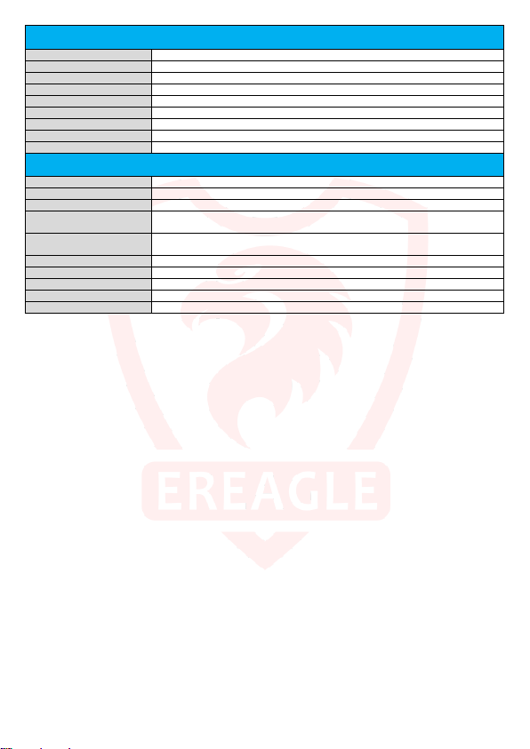
Memory:
4G~64G, TF Card, Class 10
Power supply:
4A×AA /8A×AA /12×AA alkaline batteries or rechargeable batteries(1.2~3.7V)
External Power Input:
DC 6V / 2A
Low Power Alert:
Warning tone while less than 20% of the power,auto power off while voltage less than 4.2V
Power Current:
250 mA(550mA with LED)
Operation Control
Dimension
SD Card Cycle Save: ON/OFF
Stand-by Time: 5~8 months(4A×AA ~ 12×AA)
Auto Power OFF: A uto power off in 120S while no keypad controlling
Standby Current: 400 uA(0.0004 A)
Other
: 5 + 1 joystick button, support PC-side software quickly set
Interface: DC input, SD/TF card、USB、CVBS, mode swi tch
Mounting: Bandage, tripod nail
OperatingTemperature
and Humidity:
Storage Temperature
and Humidity:
Waterproof Grade: IP68(Dust proof /Submerging test)
: 145 x 91 x 78.5mm
Net Wight: 320g
Gross Weight: 520g
Certificate: FCC, CE
-30°C~+70°C / 30% ~ 90%RH
-40°C~+85°C / 0% ~ 90%RH
32
Page 33
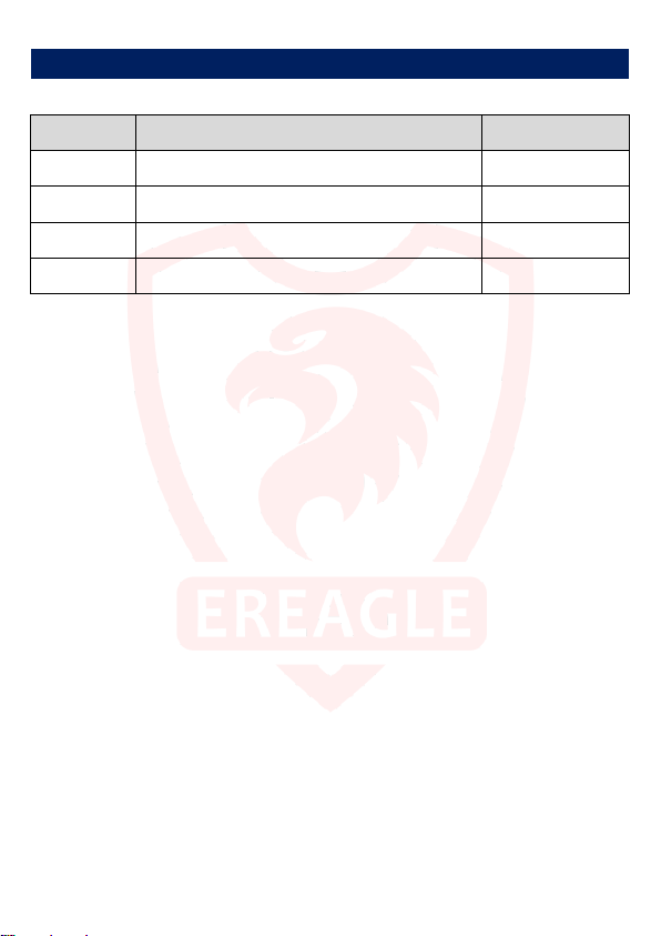
8. Packing list
item Accessories Quantity
1 Camera unit 1
2 USB cable 1
3 Camera bandage 1
4 Warranty card and brief manual 1
33
Page 34
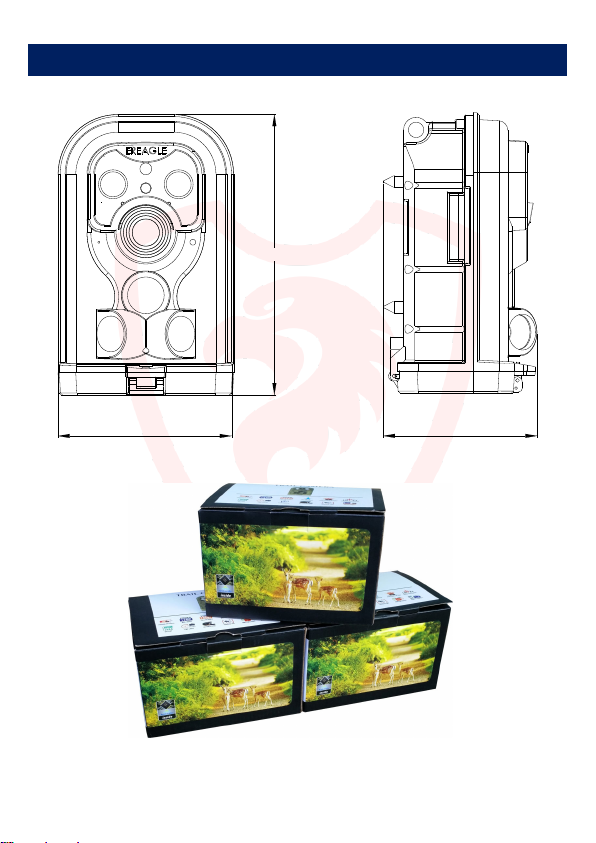
90mm
145mm
80mm
9. Dimension
34
Page 35
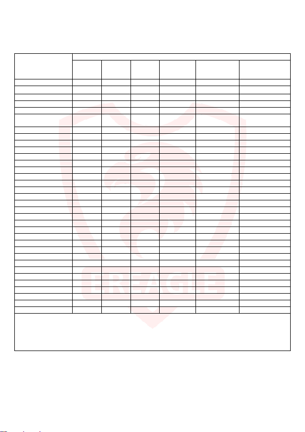
(
(
(
(
(
○ ○ ○ ○ ○ ○
To protect the environment of earth, EREAGLE pay more attention to
environment in the whole production process, and take various measures
to provide customers with more environmentally and friendly product.
Item name
Diode X ○ ○ ○ ○ ○
Resistance X ○ ○ ○ ○ ○
Rigid circuit board X ○ ○ ○ ○ ○
LED ○ ○ ○ ○ ○ ○
Integrated Circuit (IC) ○ ○ ○ ○ ○ ○
Dynamic Random access
memory (DRAM)
Capacitance ○ ○ ○ ○ ○ ○
Filter capacitor ○ ○ ○ ○ ○ ○
Filter ○ ○ ○ ○ ○ ○
Socket X ○ ○ ○ ○ ○
Light ○ X ○ ○ ○ ○
Battery ○ ○ ○ ○ ○ ○
Screw ○ ○ ○ ○ ○ ○
Metal shaft ○ ○ ○ ○ ○ ○
Cable ○ ○ ○ ○ ○ ○
Flexible printed circuit ○ ○ ○ ○ ○ ○
microphone ○ ○ ○ ○ ○ ○
inductance X ○ ○ ○ ○ ○
camera lens ○ ○ ○ ○ ○ ○
label ○ ○ ○ ○ ○ ○
carton ○ ○ ○ ○ ○ ○
user manual ○ ○ ○ ○ ○ ○
bubble pack ○ ○ ○ ○ ○ ○
filer ○ ○ ○ ○ ○ ○
rubber ○ ○ ○ ○ ○ ○
keypad ○ ○ ○ ○ ○ ○
electric wire ○ ○ ○ ○ ○ ○
case ○ ○ ○ ○ ○ ○
spring ○ ○ ○ ○ ○ ○
crystal oscillator ○ ○ ○ ○ ○ ○
IC amplifier ○ ○ ○ ○ ○ ○
switch ○ ○ ○ ○ ○ ○
CD
O:indicates that the content of the toxic and hazardous substances in all homogeneous materials of this part is below the limit specified by 11363-2003
SJ/T
X: indicates that the toxic and hazardous substances in at least one of the components of a homogeneous material exceeds the limited requirements
specified by 11363-2003 SJ/T
Note: For the components of the exceed harmful substance, it can’t be replaced as it cannot be achieved due to the global development level, but
EREAGLE are making efforts for the development of alternative technologies.
Lead
Mercury
pb)
○ ○ ○ ○ ○ ○
Toxic and harmful substance or elements
Cadmium
Hg)
Cd)
Hexavalent
Chromium
(Cr6+)
polybrominated
biphenyls
PBB)
polybrominated
diphenyl ethers
PBDE)
35
Page 36
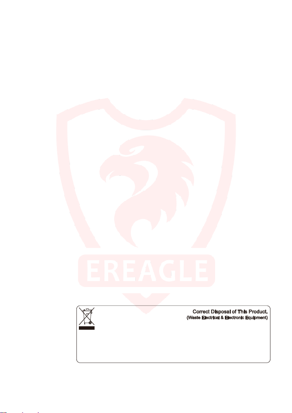
This marking s hown on the product or it s lit erature, indicat es that it s hould not be dis posed wi th other househol d wastes at the end of its working
life.
To prevent harm to the environment or human health from uncont rolled was te dispos al, pleas e separat e this from other types of w astes and
recycl e it responsi bly to promote the s ustainabl e reuse of material resourc es.
Household us ers should c ontact eit her the retailer where they purchased this product, or their l oca l govenment offi ce, for detail s o f where and
how they can t ake this item for environmental ly saf e recycli ng.
Busi ness users should contac t their suppl ier and check the terms and conditi ons of the purchas e con tract.
This product shoul d not be mixed w ith other commerci al wast es for diposal .
(Applicable in the European Union and other European countries with separate collection system)
36
 Loading...