

ERE U, L series, H series Series Manual
R U/L/H Series
User Guide, Rev. 00 (May 2015)
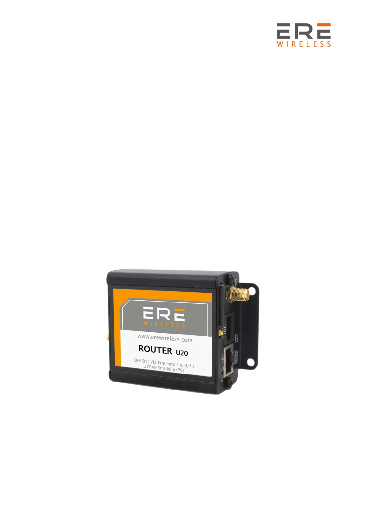
ROUTER & WiFi
ACCESS POINT
U/L/H Series
ERESRL
ViaErmannoGe,9/11|I‐27049Stradella(PV)
Phone+39038548139|Fax+39038540288
e‐mail:info@erewireless.com
website:www.erewireless.com
1

R U/L/H Series
User Guide, Rev. 00 (May 2015)
Table of contents
Table of contents..............................................................................................................................................2
Disclaimer...........................................................................................................................................................4
Technical support.............................................................................................................................................4
Warranty - Liability of the Product...............................................................................................................5
Warnings and safety instructions.................................................................................................................6
Disposal of waste by users in private households within the European Union..............................7
Installation..........................................................................................................................................................7
Mechanical.................................................................................................................................................................7
Electrical (wiring)....................................................................................................................................................7
Antenna............................................................................................................................... ........................................7
Modem version..................................................................................................................................................8
1General presentation................................................................................................................................9
1.1Front panel.....................................................................................................................................................9
1.2Back panel............................................................................................................................... .......................9
1.3External connections..................................................................................................................................9
1.3.1Interfaces and connectors...............................................................................................................9
2Basic features and services..................................................................................................................12
3Using the modem.....................................................................................................................................13
3.1Setting up the modem.............................................................................................................................13
3.1.1Inserting SIM card(s)........................................................................................................................13
3.1.2Connecting antenna.........................................................................................................................13
3.1.3Connecting power supply cable..................................................................................................14
3.1.4Connecting UTP cable with RJ-45................................................................................................14
3.2Modem configuration...............................................................................................................................14
3.2.1Setting up the connection..............................................................................................................15
3.2.2Modem status page..........................................................................................................................15
3.2.3Local network......................................................................................................................................16
3.2.4GSM network.......................................................................................................................................17
3.2.5WiFi network........................................................................................................................................17
3.2.6Connection control...........................................................................................................................18
3.2.7Ports configuration...........................................................................................................................19
3.2.8TCP/IP forwarding............................................................................................................................20
3.2.9VLAN.......................................................................................................................................................21
3.2.10Static routes.....................................................................................................................................22
3.2.11Dynamic DNS...................................................................................................................................23
3.2.12Access control.................................................................................................................................24
2

R U/L/H Series
User Guide, Rev. 00 (May 2015)
3.2.13Open VPN..........................................................................................................................................26
3.2.14Ipsec static/Ipsec mobile...........................................................................................................27
3.2.15Generating SSL certificates........................................................................................................30
3.2.16N2N......................................................................................................................................................31
3.2.17CARP...................................................................................................................................................32
3.2.18NTRIP configuration page..........................................................................................................33
3.2.19SMS Actions......................................................................................................................................34
3.2.20GPIO....................................................................................................................................................35
3.2.21CAN.....................................................................................................................................................37
3.2.22Time....................................................................................................................................................38
3.2.23Syslog.................................................................................................................................................38
3.2.24User files...........................................................................................................................................39
3.2.25Backup and restore.......................................................................................................................40
3.2.26Discard changes.............................................................................................................................41
3.2.27Save settings...................................................................................................................................41
3.3System logs description..........................................................................................................................42
3.4Device Manager.........................................................................................................................................43
4Troubleshooting......................................................................................................................................45
4.1No communication with the modem..................................................................................................45
4.2Modem answers but there is no internet connection..................................................................45
5Technical characteristics.......................................................................................................................46
5.1Mechanical characteristic......................................................................................................................46
5.2Housing (dimension diagram).............................................................................................................. 46
5.3Electrical characteristic.......................................................................................................................... 47
5.3.1Power supply............................................................................................................................... ........47
5.3.2RF characteristics..............................................................................................................................47
5.4Environmental characteristic...............................................................................................................49
6Terminal architecture.............................................................................................................................50
7Safety recommendations.......................................................................................................................51
7.1General Safety............................................................................................................................................51
7.2Care and Maintenance............................................................................................................................51
7.3Responsibility............................................................................................................................... ...............51
8Conformity Assessment Issues...........................................................................................................52
9Certifications............................................................................................................................................53
10List of Acronyms..................................................................................................................................54
3

R U/L/H Series
User Guide, Rev. 00 (May 2015)
Disclaimer
All rights to this manual are owned solely by ERE Srl (referred to in this user guide as ERE).
All rights reserved. The copying of this manual (without the written permission from the owner) by
printing, copying, recording or by any other means, or the full or partial translation of the manual
to any other language, including all programming languages, using any electrical, mechanical,
magnetic, optical, manual or other methods or devices is forbidden.
ERE reserves the right to change the technical specifications or functions of its products, or to
discontinue the manufacture of any of its products or to discontinue the support of any of its
products, without any written announcement and urges its customers to ensure, that the information
at their disposal is valid.
ERE software and programs are delivered ”as is”. The manufacturer does not grant any kind of
warranty including guarantees on suitability and applicability to a certain application. Under no
circumstances is the manufacturer or the developer of a program responsible for any possible
damages caused by the use of a program. The names of the programs as well as all copyrights
relating to the programs are the sole property of ERE. Any transfer, licensing to a third party, leasing,
renting, transportation, copying, editing, translating, modifying into another programming language
or reverse engineering for any intent is forbidden without the written consent of ERE.
Technical support
Our website www.erewirless.com contains many useful information, user guides and configuration
software and technical documents always update to the latest version.
If you have technical problems or cannot find the required information in the provided documents,
contact our Technical Support by email at info@erewireless.com or by phone +39 0385 48139
4

R U/L/H Series
User Guide, Rev. 00 (May 2015)
Warranty - Liability of the Product
Supplier represents and warrants that products are manufactured in accordance with the applicable
specifications and are free from defects in materials and workmanship. The warranty, valid for a
period of 12 months of use, maximum 18 months from the date of delivery, shall not cover defects
caused by accident, Buyer’s negligence, improper use or maintenance or by any other reason beyond
Supplier’s control.
Buyer shall have 10 (ten) working days following receipt of products to inspect the products and to
notify to Supplier in writing any defects or non-compliance. In the event that any shipment of
products is not accepted by Buyer due to any non-conformity with the specifications, or as a result
of a cause occurred prior to placement thereof with the carrier, Buyer shall, if so indicated in writing
by the Supplier, promptly return some samples or the full shipment that was rejected by Buyer at
Buyer’s costs.
Supplier, at its own discretion, shall, within a reasonable period, considering the entity of the
complaint: (i) send a replacement shipment of products conforming, or (ii) credit Buyer a sum equal
to the value of the defective or non-conforming products. This warranty overwrites all legal
warranties for defects and compliance and exempts Supplier from any other responsibility for the
supplied products; in particular, Buyer shall not be entitled to any requests for compensation or
price reductions.
If one of the products sold by the Supplier to the Buyer is defective, the Buyer will send it, at its own
expense, at the headquarters of the Italian Supplier. The product will be repaired or replaced by the
Supplier, at no costs to the Buyer.
The Buyer will pay all the shipping costs for the product repaired or replaced and sent back to the
Buyer.
The Buyer will bear all costs related to disassembly, assembling and transportation of the product,
and any damage caused by the "machinery inactivity".
Supplier shall indemnify Buyer against any liability of the products claims asserted by third parties
relating to damages sustained as a result of a defective products. In such case Supplier shall
reimburse Buyer exclusively within the limits, terms and conditions of the products liability insurance
policy held by Supplier. Buyer shall not make any oral or written representations which vary from
the specifications, operating instructions, labels or representations given or made by Supplier with
respect to the products. If any liability is incurred because of such varying representations, Buyer
holds Supplier harmless with respect to any such representations.
In no event shall Supplier be liable for any indirect, incidental, exemplary or consequential damages,
including without limitation any claim for damages based on lost revenues or profits, however
caused.
In no event shall the Supplier be liable for any costs or damages arising from any act or omission of
Buyer, including, without limitation, relating to the modification, handling, storage and marketing
of Products by Buyer or to Buyer’s failure to provide its employees, agents and customers or other
third parties with adequate instruction as to the proper handling and use of Products.
In this respect we hereby confirm that our products are not designed for nuclear applications neither
for aircraft/aerospace industries. For the above mentioned applications both warranty and insurance
coverage do not apply.
5

R U/L/H Series
User Guide, Rev. 00 (May 2015)
Warnings and safety instructions
READ CAREFULLY
The unit does not provide protection from lightning and surge.
For outdoor installation use outdoor nonmetallic case safety approved according UL 50. Additionally
you should provide protection from lightning and over voltage according National code.
Be sure the use of this product is allowed in the country and in the environment required.
The use of this product may be dangerous and has to be avoided in the following areas:
Where it can interfere with other electronic devices in environments such as hospitals,
airports, aircrafts, etc.
Where there is risk of explosion such as gasoline stations, oil refineries, etc. It is
responsibility of the user to enforce the country regulation and the specific environment
regulation.
Do not disassemble the product; any mark of tampering will compromise the warranty validity.
We recommend following the instructions of the hardware user guides for a correct wiring of the
product.
The product has to be supplied with a stabilized voltage source and the wiring has to be conforming
to the security and fire prevention regulations.
The product has to be handled with care, avoiding any contact with the pins because electrostatic
discharges may damage the product itself. Same cautions have to be taken for the SIM, checking
carefully the instruction for its use. Do not insert or remove the SIM when the product is in power
saving mode.
The system integrator is responsible of the functioning of the final product; therefore, care has to
be given to the external components of the unit, as well as of any project or installation issue,
because the risk of disturbing the GSM network or external devices or having impact on the security.
Should there be any doubt, please refer to the technical documentation and the regulations in force.
Every unit has to be equipped with a proper antenna with specific characteristics. The antenna has
to be installed with care in order to avoid any interference with other electronic devices and has to
guarantee a minimum distance from the body (20 cm/8”). In case this requirement cannot be
satisfied, the system integrator should assess the final product against the SAR regulation.
The European Community provides some Directives for the electronic equipment introduced on the
market. All the relevant information available on the European Community website:
http://europa.eu.int/comm/enterprise/rtte/dir99-5.htm
The text of the Directive 99/05 regarding telecommunication equipment is available, while the
applicable Directives (Low Voltage and EMC) are available at:
http://europa.eu.int/comm/enterprise/electr_equipment/index_en.htm
6

R U/L/H Series
User Guide, Rev. 00 (May 2015)
Disposal of waste by users in private households within the European Union
According to Directive 2012/19/EU of the European Union on waste electrical
and electronic equipment (WEEE) this product must not be disposed off with
your other household waste, it is your responsibility to dispose of your waste
by taking it to a collection point designated for the recycling of electrical and
electronic appliances.
Separate collection and recycling of your waste at the time of disposal will
contribute to conserving natural resources and guarantee recycling that
respects the environment and human health.
For further information concerning your nearest recycling centre, please contact your nearest local
authority/town hall offices.
Installation
Mechanical
The device must be installed in a location that is sufficiently ventilated so that there is no risk of
internal heating. Place the device against a flat, firm and stable surface. It is not recommendable to
install the device on a strongly vibrating surface. Suitable dampening and/or isolation materials
should be used in cases where the installation surface will be subjected to vibration.
Electrical (wiring)
To prevent damage both the device and any terminal devices must always be switched OFF before
connecting or disconnecting the connection cable. Before connecting any power cables the output
voltage of the power supply should be checked.
The product has no disconnecting device. An external disconnecting device must be installed. This
must be close to the equipment.
The product has to be supplied with a stabilized voltage source and the wiring has to be conforming
to the security and fire prevention regulations.
Antenna
The device’s antenna must be free and at least 10 cm away from any conducting material. When the
antenna is installed outside, it is essential to connect the cable screen to the building’s earth. We
recommend using lightning protection. The protection kit chosen must permit the coaxial cable to
be earthed (eg: coaxial lightning arrester with earthing of the cable at different places on the antenna
at the base of pylons and at the entry, or just before entering the premises).
7
R U/L/H Series
User Guide, Rev. 00 (May 2015)
Modem version
There are many ways to upgrade your U/L/H modem. List below shows typical configuration and
different combinations (versions) of this terminal.
Option Typical Option
Power supply 6-30V 6-30V
CPU IMX286 450MHz IMX286 450MHz
128MB RAM, 512MB MicroSD card
Memory
(part used for Linux system, the
size of SD card can be changed in
-
the future)
RS232 Systems console Second RS485, instead of RS232
RS485 1 2
I/O connectors -
4 digital inputs, 4 digital outputs,
ADC output, 2 analog inputs, I
CAN interface, 3.3V output power
2
C,
supply, audio I/O, miniUSB 2.0
Connection HSPA+ (GSM, GPRS, EDGE) UMTS, LTE
SIM Extractable Built-in
Dual SIM - Option unavailable
Mono microphone. Stereo input
Audio codec -
LINE IN, Stereo output LINE OUT, or
Speaker output SPK OUT
LAN Ethernet 10/100Mbps WiFi modem
8
R U/L/H Series
User Guide, Rev. 00 (May 2015)
1 General presentation
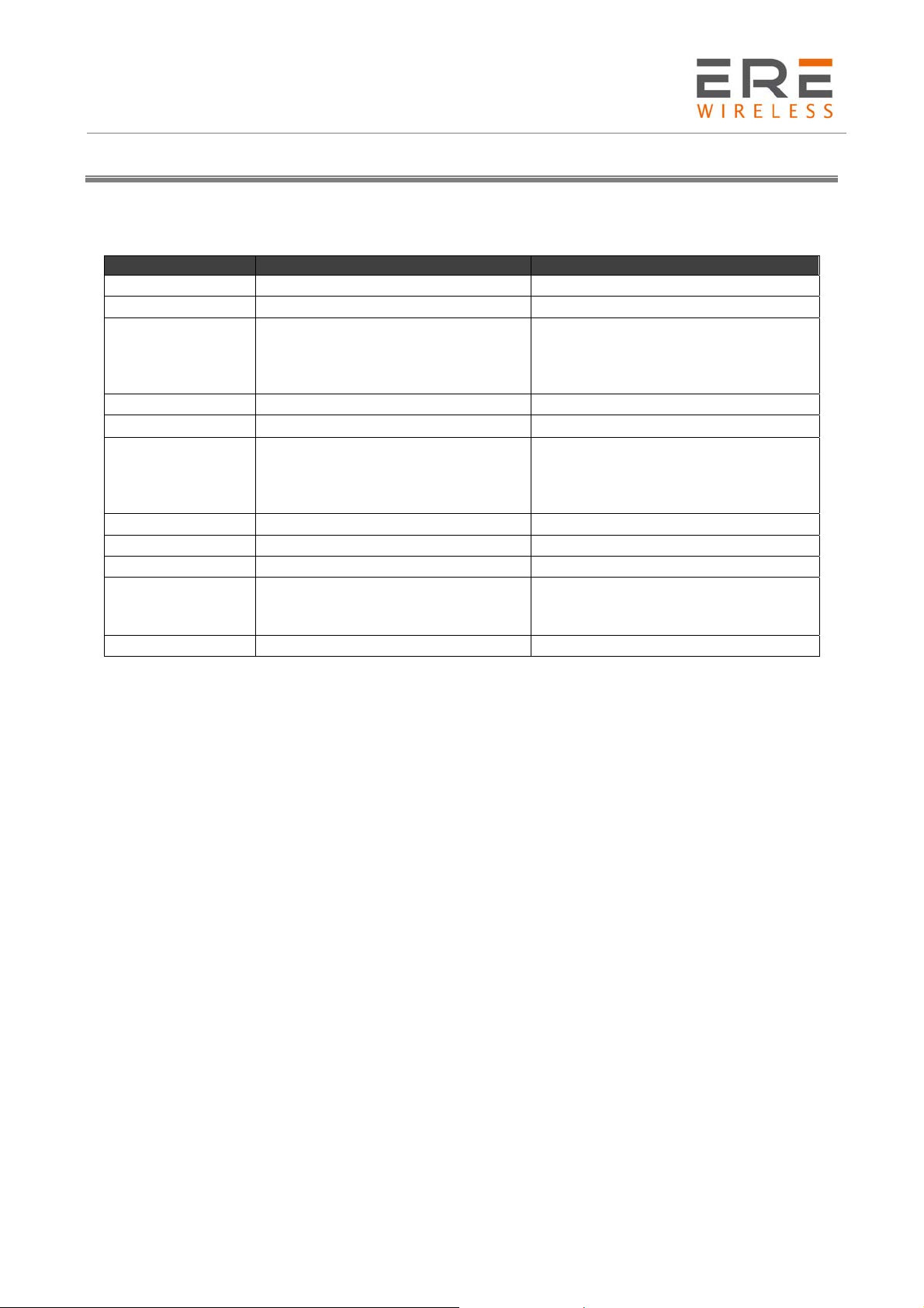
1.1 Front panel
1.2 Back panel
1.3 External connections
1.3.1 Interfaces and connectors
1.3.1.1
SMA antenna connector placed on front panel is used to connect external GSM. To establish
connection with GSM network an external antenna must be used. Type of antenna depends on GSM
coverage. In good circumstances (level of received signal is high) use antenna which is attached in
the package. If range of GSM is low or none, an outdoor directional/omnidirectional or indoor (for
instance in place where GSM range is sufficient) antenna should be used.
Note: If there is no antenna connected to SMA connector, the connection with GSM network is
impossible.
GSM antenna connector
9
R U/L/H Series
User Guide, Rev. 00 (May 2015)
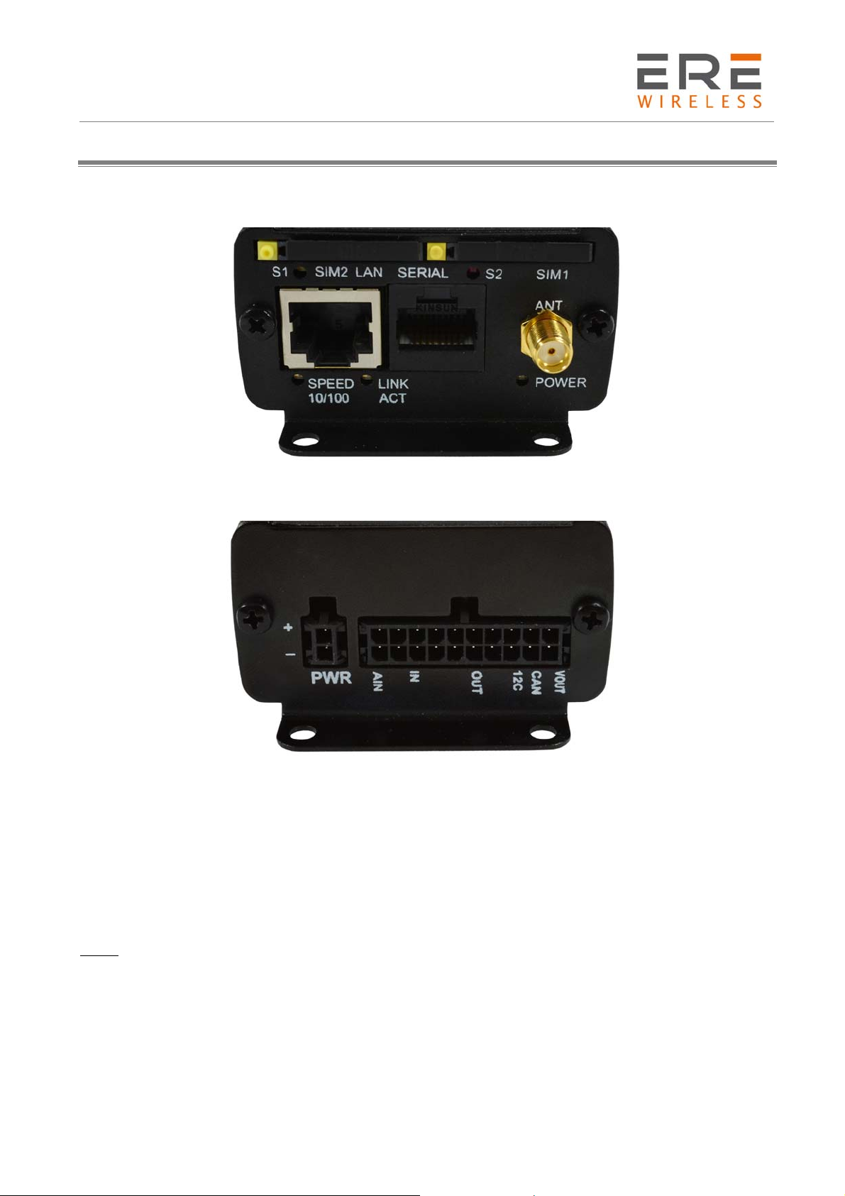
1.3.1.2
Serial RS232/RS485 (through RJ-45 connector) is placed on front panel of modem and it can be
configured for special use as an option for customer.
RS232
RS485
A A1 1 5V 2 2 2
5V 5V 2 B 3 3 nc
B B1 3 GND 4 nc nc
GND GND 4 TX 5 5 5
TX A2 5 RX 6 nc 6
RX B2 6 RTS 7 7 nc
RTS NC 7 CTS 8 8 nc
CTS NC 8
Modem serial port, either full RS232/RS485
Version U/L/H RS232 RS485
2x
RS485
RJ45 A 1 nc 1
U/L/H RJ45 DB9F DB9F
1.3.1.3
RJ-45 connector is placed on front panel of U/L/H modem and used for communication with PC or
laptop to plug cable for Ethernet. In order to start configuration pages of modem plug UTP cable
between RJ-45 of modem and RJ-45 of your computer. Configuration pages are available in the web
browser under IP address specified on the modem (default address is 192.168.1.234).
1.3.1.4
In the U/L/H modem power supply 6V-30V care must be taken to ensure “clean” power supply input
and especially to avoid short transients on power supply lines originating from inductive load
switching.
1.3.1.5
Audio Input and Output lines are available as option. There are three lines available:
SPK/LINE OUT – external speaker or line out
LINE IN
MIC IN –microphone plug
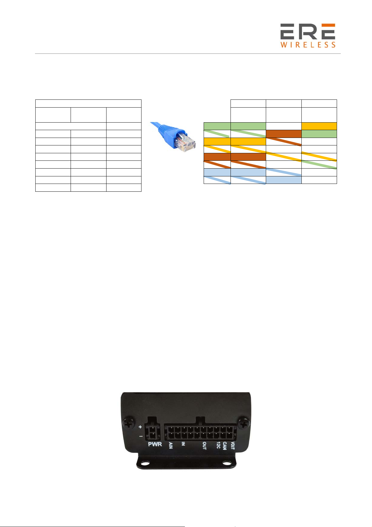
1.3.1.6
U/L/H is available with 20pin connector as an option. Detailed description is shown below.
RJ-45 connector
RJ-45 connector
Audio I/O
20-pin connector
10
R U/L/H Series
User Guide, Rev. 00 (May 2015)
PIN*
Upper row
Function
PIN*
Lower row
Function
1 ADC IN1 2 ADC IN2
3 DAC OUT 4 GND (not main supply input)
5 GND (not main supply input)
6 GND (not main supply input)
7 IN1 8 IN2
9 IN3 10 IN4
11 OUT1 12 OUT2
13 OUT3 14 OUT4
15 I2C SDA 16 I2C SCL
17 CAN L 18 CAN H
19 GND (not main supply input)
20 +3.3V output, 75mA max.
GND – ground. Do not connect directly with minus of power supply input.
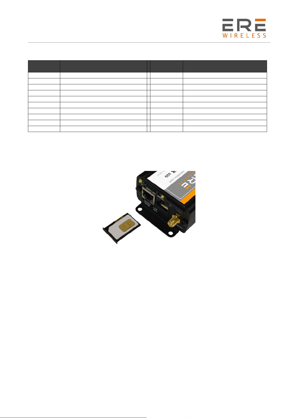
1.3.1.7
SIM card holders
SIM card holders are placed in front panel of U/L/H. To insert SIM card into the extractable holder
push yellow button and take holder out. Place SIM card as show in the picture. To operate the
module in a GSM network, it is necessary to insert at least one SIM card obtained from the network
operator.
11

R U/L/H Series
User Guide, Rev. 00 (May 2015)
2 Basic features and services
Basic features and available services are contained in table below.
Feature / service Description
Supported
bands
All variants:
• GSM 900 Class 4 (2W)
• DCS 1800 Class 1 (1W)
• EDGE 900MHz Class E2 (0.5W)
• EDGE 1800MHz Class E2 (0.4W)
HSPA+ variant:
• WCDMA FDD B1, B2, B4, B5, B8 Class 3 (0.25W)
UMTS variant:
• WCDMA FDD B1, B8 Class 3 (0.25W)
LTE variant:
• WCDMA FDD B1, B5, B8 Class 3 (0.25W)
• LTE FDD B3, B7, B20 Class 3 (0.2W)
Data features
HSPA+ (downlink 21 Mbit/s, uplink 5,76 Mbit/s)
UMTS (downlink 7,2 Mbit/s, uplink 5,76 Mbit/s)
EDGE (Multi-slot class 10, max BR downlink 236,8 Kb/s)
GPRS (Multi-slot class 10, max BR downlink 85,6 Kb/s)
CSD (Max BR 14,4 Kb/s)
Embedded protocols: TCP/IP, UDP/IP, SSL, HTTP, HTTPS, FTP, SMTP,
POP3, IBM MQTT
Class B GSM 07.10 multiplexing protocol
WiFi Standard:
• 802.11b/g/n, 802.3, 802.3u
Date rate
• up to 150 Mbps
Power supply
Nominal voltage range: 6V-30V
Maximum continuous (average) supply power: 5W
Peak (momentary) supply current: 1 A
Interfaces
(typical version)
GSM antenna connector: SMA
1x SIM Card: 1.8V, 3V standards
RS232 and RS485 via RJ-45
RJ-45 connector (x2)
miniUSB (OTG)
power supply connector
Options*
Dual SIM
I/O interfaces (CAN, 3.3V output,)
Audio I/O
WiFi antenna connector: SMA
Other Physical size:
Max. Dimensions: 83 x 60 x 34 mm (w/ connectors)
Operating temperature range:
Min. -20°C Max. 45°C
*option
12
R U/L/H Series
User Guide, Rev. 00 (May 2015)
3 Using the modem
3.1 Setting up the modem
To set the modem, do the following steps:
3.1.1 Inserting SIM card(s)
Push yellow button place on front panel and take SIM holder drawer out.
Place SIM card(s) in the holder(s) as shown in the picture:
*modems are available with one or two SIM cards
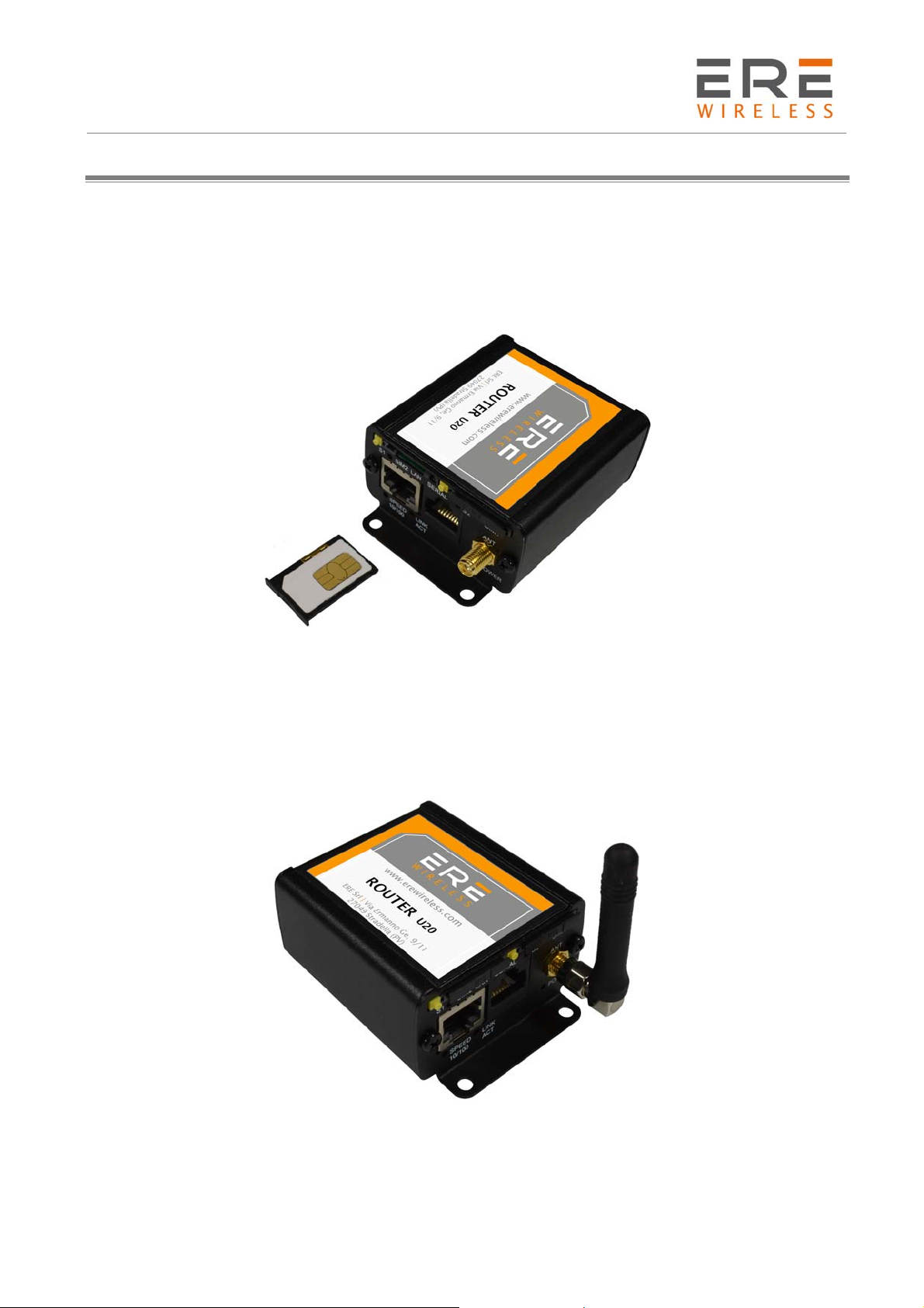
3.1.2 Connecting antenna
Connect the GSM antenna to the SMA connector, or both GSM and GPS in optional versions
of the modem.
13
R U/L/H Series
User Guide, Rev. 00 (May 2015)
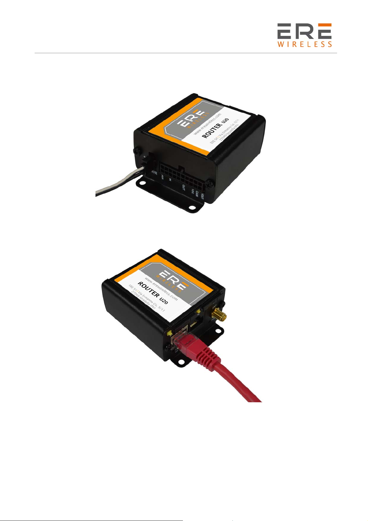
3.1.3 Connecting power supply cable
Connect power supply cable into power supply connector
3.1.4 Connecting UTP cable with RJ-45
Plug UTP or similar cable to RJ-45 plug.
3.2 Modem configuration
Modem is configured via web browser making it portable and easy to use. Modem configuration is
described below in following sections. Modem settings are divided into sections which allows user
to easily find option needed. When switching tabs settings are automatically saved in modem
cache, to save settings permanently and apply them click Save Settings in menu. You can also
discard changes by choosing appropriate option from the bottom of the menu.
WARNING: Cache is cleared on modem reset or pulling the power cable out.
WARNING: Not all tabs are available on every modem version.
14
R U/L/H Series
User Guide, Rev. 00 (May 2015)
3.2.1 Setting up the connection
After you connect all necessary cables (see Setting up the modem Setting up the modem) you can
set up connection. Connect UTP cable to your computer and go to Internet protocol TCP/IP
properties (Network connections -> Local Area Connection ->Internet protocol TCP/IP->
Properties) and set your IP address as 192.168.1.x. Please read how to change TCP/IP settings of
your network card in this thread (for Windows 7):
http://windows.microsoft.com/en-us/windows/change-tcp-ip-settings#1TC=windows-7
Now modem will connect your computer and its configuration page can be seen by going to default
IP address in your browser 192.168.1.234.
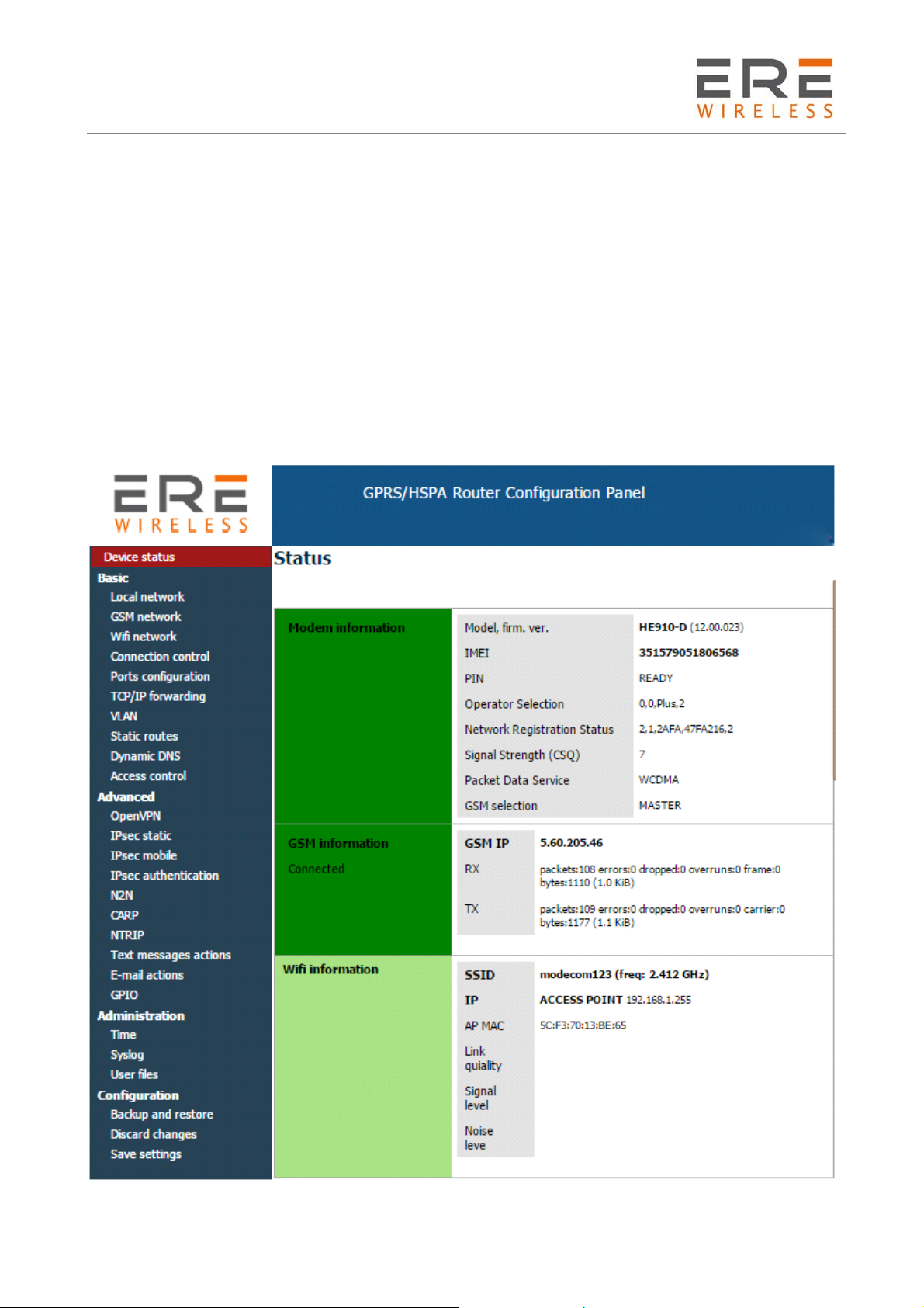
3.2.2 Modem status page
Go to your web browser and put IP address 192.168.1.234. You will be asked for username and
password. By default it is:
Username: admin
Password: 12345
If everything is configured correctly you should see following screen:
15
R U/L/H Series
User Guide, Rev. 00 (May 2015)
This is Status page of your modem. Here you can see if modem is connected/disconnected
from net and its parameters and parameters of PPP connection.
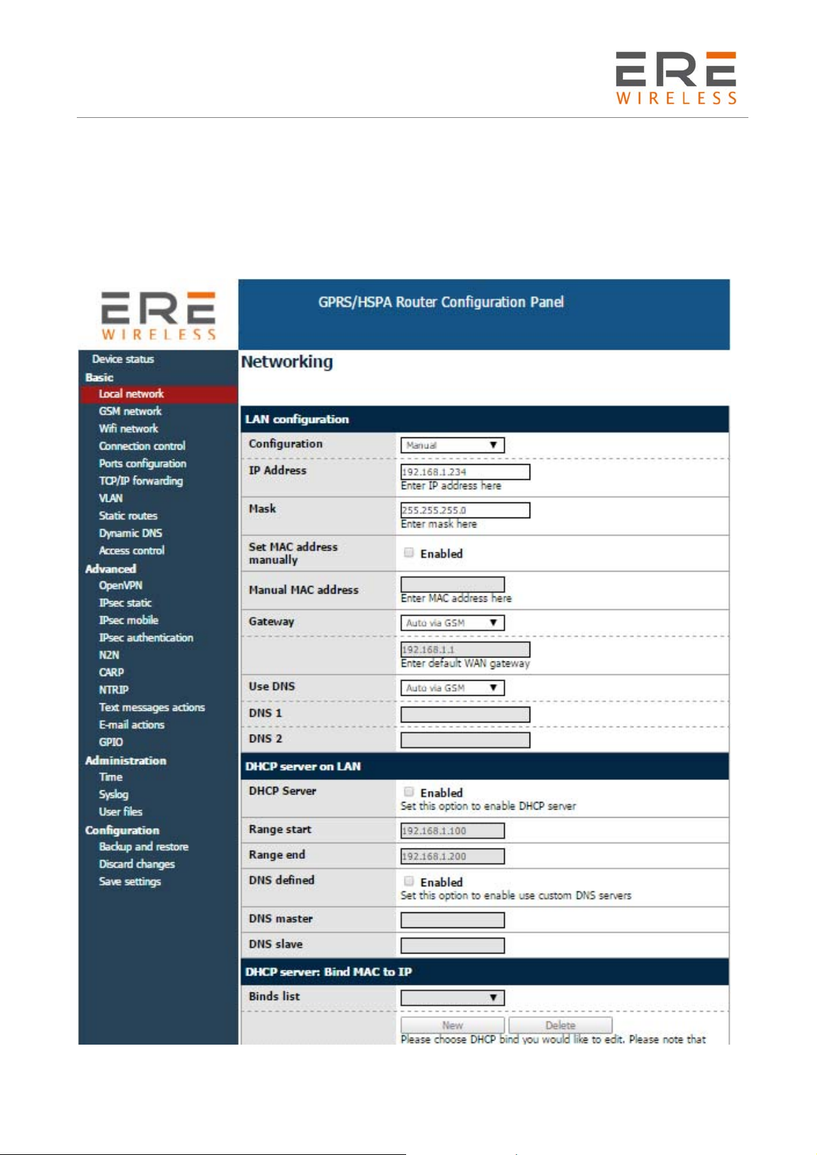
3.2.3 Local network
On LAN configuration page you can find essential parameters needed for LAN connection. Here
you can set IP Address (or set it to be downloaded via DHCP), mask, default gateway, DNS
addresses. Last two options can be entered manually or downloaded automatically via GSM or
DHCP. Modem can also work as DHCP server-you can define its range and set list of IP-MAC binds.
16
R U/L/H Series
User Guide, Rev. 00 (May 2015)
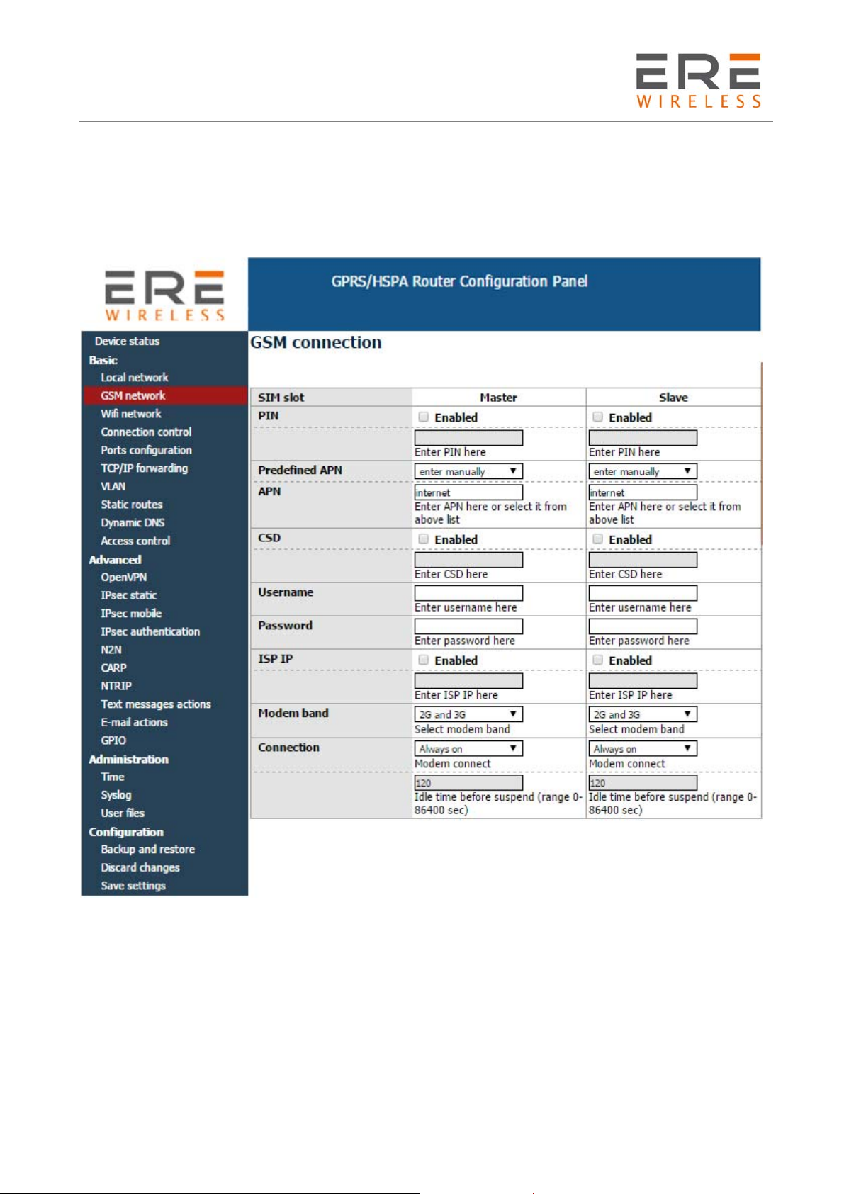
3.2.4 GSM network
On ISP Master page you can define internet connection parameters (APN, username, password,
CSD, ISP IP and Modem band) for one or two SIM cards (depending on modem version). To use
internet you should know those parameters - they are essential for getting access to internet. The
parameters should be ensured by your mobile network provider. You can find them by contacting
your GSM network provider or visiting its website.
To enter the PIN for SIM card you need to mark “Enable” field and then fill the field below with
correct PIN. Outgoing calls are made always on MASTER SIM card.
3.2.5 WiFi network
“WiFi network” tab is available only in U/L/H with WiFi option. In this menu you can set parameters
of your WiFi connection. To scan all available networks please use “Scanning” button. You will
redirect to a page with a list of networks. You can set a WiFi mode (Access point or Station), fill a
name and password of selected network. You can also enable DHCP server and AP clients.
17
 Loading...