

Page 1
®
060® Super Bender
Rotary Draw Bender for Pipe, Tube and Prole Bending
Operator’s Manual
BEFORE USE, BE SURE EVERYONE USING THIS MACHINE READS AND
THOROUGHLY UNDERSTANDS ALL SAFETY AND OPERATING INSTRUCTIONS IN THIS MANUAL
Model 060A___________________ Serial # __________________________
WARNING!
-1-
Page 2

060
®
Super Bender
®
Rotary Bender
Pipe, tube and prole bending machine
Congratulations on your purchase of an Ercolina® bending machine from CML USA Ercolina®. Ercolina
machines are designed and manufactured to deliver years of trouble-free bending performance. Please
take a moment to complete and mail your warranty registration card. Doing so validates the machine
warranty period and ensures prompt service if needed. Thank you for selecting products from CML USA
Ercolina®.
Table of Contents
Important safety instructions 3
Special Instructions 4
Before you begin and general identication 5
®
060
Super Bender
Wiring instructions, general assembly and setup, and bending terminology 7
Material selection and mounting tooling 8-9
Ercolina® rotary draw tie bar assembly 10-11
Bender programming 12-13
Bending troubleshooting 14
Accessories and maintenance 15
Voltage troubleshooting, voltage test readings 16
Grounding and wiring schematics 17-18
Material length required for rotary bends in pipe (tube and pipe information) 19
Conversion Tables - mm to inches and inches to mm 20
Minimum distance between bends by center line radius, pipe and tube kits 21
Tube, pipe and prole benders 22
Angle rolls 23
®
features and specications 6
®
——— Limited Warranty ———
CML USA Ercolina® will, within (1) one year of the original date of purchase, repair or replace any goods
found to be defective in the material or workmanship, provided the warranty registration card has been
returned to CML USA Inc. Ercolina® within (30) thirty days of the purchase date. This warranty does not
apply to machines and/or components that have been altered, changed or modied in any way, or
subjected to use beyond recommended capacities and specications. Electrical components subject
to respective manufacturers’ warranties. All goods returned defective should be returned prepaid freight to
CML USA Inc. Ercolina®, which shall be the buyer’s sole and exclusive remedy for defective goods.
This warranty excludes labor and travel-related expenses, which may be incurred during the warranty
period. In no event shall CML USA Inc. Ercolina® be liable for the loss or damage resulting directly or
indirectly from the use of merchandise or from any other cause. CML USA Inc. Ercolina® is not liable for any
costs incurred on such goods or consequential damages. No ofcer, employee or agent of CML USA Inc.
Ercolina® is authorized to make oral representations or warranty of tness or to waive any of the foregoing
terms of sales and none shall be binding on CML USA Inc. Ercolina®.
_____________________________________________________
CML USA Ercolina® reserves the right to make improvements and
_____________________________________________________
modications to design without prior notice.
-2-
Page 3

Important Safety Instructions
WARNING!
When using electric tools, basic safety precautions should always be followed to reduce the risk of re,
shock and personal injury.
1. Keep Work Area Clean
Cluttered areas and benches invite injuries.
2. Consider Work Area Environment
Do not expose power tools to rain.
Do not use the power tools in damp or wet locations.
Keep work area well lit.
Do not use a tool in presence of ammable liquids or gases.
3. Guard Against Electric Shock
Prevent body contact with grounded surfaces. For example; pipes radiators, ranges,
refrigerator enclosures.
4. Keep Children Away
Do not let visitors contact tool or extension cord.
All visitors should be kept away from work area.
5. Store Idle Tools
When not in use, tools should be stored in a dry and high or locked-up place out of
reach of children.
6. Do Not Force Tool
It will do the job better and safer at the rate for which it was intended.
7. Use The Right Tool
Do not force small tool or attachment to do the job of a heavy-duty tool.
Do not use the tool for purpose not intended, for example; do not use a circular saw for
cutting tree limbs or logs.
8. Dress Properly
Do not wear loose clothing or jewelry; they can be caught in moving parts.
Rubber gloves and non-skid footwear are recommended.
9. Use Safety Glasses
Also use face mask or dust mask if operation is dusty.
10. Do Not Abuse Electric Cord
Never yank electrical cord.
Keep electric cord from heat, oil and sharp edges.
11. Do Not Overreach
Maintain proper footing and balance at all times.
12. Maintain Tools With Care
Keep clean for better and safer performance.
Follow instructions for lubricating and changing accessories.
Inspect tool cords periodically and if damaged, have repaired by authorized service facility.
Inspect electrical cords periodically and replace if damaged.
Keep handles dry and clean and free from oil and grease
-3-
Page 4

13. Disconnect Tools
Disconnect machine from power source when not in use, before servicing and changing
accessories.
14. Remove Adjusting Keys and Wrenches
Form a habit of checking to see that keys and adjusting wrenches are removed from machine
before turning it on.
15. Avoid Unintentional Starting
Always disconnect from power source before moving.
16. Stay Alert
Watch what you are doing. Use common sense, do not operate tool when you are tired.
(Do not use when taking medications that may cause drowsiness.)
17. Check Damaged Parts
Before further use of the machine, guard or other part that is damaged should be carefully
checked to determine that it would operate and perform its intended function.
Check alignment of moving parts, binding of parts, breakage of parts mounting and any
other conditions that may affect its operation. A guard or other part that is damaged should
be properly repaired or replaced by an authorized service center. Do not use this machine
if switches do not turn it on and off. Have defective switches replaced by authorized service
center.
Special Instructions
1. Read and follow operators manual thoroughly. If you require an additional manual please contact
CML USA Ercolina® at 563-391-7700 or email [email protected].
2. Due to size and weight, it is recommended that qualied professionals transport, position and
install the bending machine. Use proper equipment for installation including lift truck safety
straps, chains binders and bars. Machine must be balanced evenly at all times.
3. Never place hands, nger gloves or clothing near rotation machine parts.
4. Always disconnect machine from power source before changing accessories.
5. Always use eye and hearing protection.
6. Never wear loose clothing, gloves or jewelry when working near machine.
7. Stand in a safe position when operating machine.
8. Always wear safety approved steel toe footwear.
9. Make provision for safe handling of heavy and/or awkward materials.
10. Use only proper tooling, keep tooling securely fastened.
11. Keep machine and tooling free and clear of chips and debris.
12. Keep all safety features functioning and working properly.
13. Do not alter or modify machine. Use only OEM approved parts and accessories.
-4-
Page 5
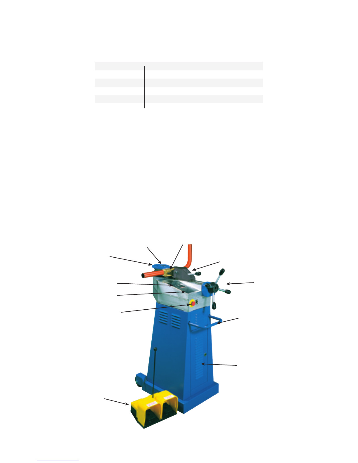
Before you Begin
Inspect machine to be sure following equipment arrived and no damage occurred during shipment.
®
060
Super Bender® and Standard accessories
060A Super Bender® model 060
®
050A 40mm hex shaft
050B 50mm hex shaft (mounted on machine)
050D Support bracket for counterbending die
050G Hand wheel
050H Foot Pedal
General Identication of Parts
1. Foot pedal switch 7. Counterbending die
2. Emergency stop 8. Counterbend die vise
3. Programming 9. Counterbend die hand wheel
4. Control panel with display 10. Transportation handle
5. Center former die 11. Access Panel
6. Hex shaft
5 - Center
former die
4 - Control panel
with display
3 - Programming
2 - Emergency
stop button
1 - Foot pedal switch
6 - Hex
shaft
7 - Counterbending
Die
8 - Counterbend
die vise
9 - Counterbend die
hand wheel
10 - Transportation
handle
11 - Access panel
-5-
Page 6

060
®
Super Bender
®
Features
● Bends material to ¼″ to 2½″ diameters
● Heavy-duty gear case with maximum 8⅞″ CLR
● Patented tooling system achieves CLR two times diameter without mandrel
● Low voltage 24V controls
● Programmable springback settings ensure bend accuracy for a wide variety of material
● Programmable bend angles 0 to 180°
● Remote foot pedal for hands free operation
● Patented swing away vise system and hex mounted tooling increase productivity
● Overload protection controls
● Standard multiple language capability
● Transportation wheels and lift handle built into base cabinet
● Tool free tooling changes with multiple CLR available for each diameter
● Accepts Ercolina® two axis A40/P positioner table
● No hydraulics
● Comprehensive (1) one-year warranty
Machine Capacities
Material Maximum Maximum
Diameter Thickness
Pipe 1.5″ ID Schedule 40
Mild steel tube 2″ .140
Soft brass 1⅞″ .125
Stainless steel 1⅞″ .109
Welded furniture tube 2⅛″ .125
ST 35 hydraulic steel 2″ .156
304L hydraulic stainless 2″ .125
Hard copper and aluminum 2½″ .156
Round solids 1¼″ –
Rectangular solids ⁵⁄₁₆″ x 1⅞″ –
Rectangular tube ¹³⁄₁₆″ x ⁹⁄₁₆″ .125
Square tube 1⁹⁄₁₆″ x 1⁹⁄₁₆″ .125
Square solids 1³⁄₁₆″ x 1³⁄₁₆″ –
Mild steel T 1⁹⁄₁₆″ x 1⁹⁄₁₆″ .187
Mild steel C channel 1¼″ x ⅝″ .187
All capacities based on mild grade material using machine at low bending speed;
Heavy wall and high tensile materials reduce machine capacity.
Height x Length x Width 36″ x 24″ x 10″
Bending speed Two speed 1.7
Motor 120 volt single phase 50/60 cycle
Minimum and Maximum CLR ⅜″ - 8⅞″
Bending angle range 0 to 180
Weight 189 lbs.
Dimensions and Specications
◦
-6-
Page 7

Wiring Instructions and Connections
Attention! 060® Super Bender® machines ship 120V single phase. Have a qualied electrician connect
your machine according to the following instructions. Note: CML USA Ercolina® is not responsible for
damage that may occur from improper installation.
1. Determine location of machine installation.
2. Measure incoming line voltage at power source.
3. Conrm incoming line voltage matches machine’s voltage rating.
4. 060®’s are equipped with two multi-tap transformers (TR1 and TR2).
Voltage taps on (TR1) and (TR2) transformers must be set to match incoming line voltage.
5. Access front panel to make necessary adjustments to electrical controls.
6. Complete wiring installation, close and lock cabinet door.
(Note to electrician: When connecting machine to WYE power supply, connect highleg to wire #52 at
machine. See diagram.)
7. Release emergency stop switch and rotate main power switch to “ON” position.
If panel displays “rotation error”, turn machine power “OFF”, rotate power switch in opposite direction
to automatically change phasing.
General Assembly and Setup
- Connecting foot pedal -
Insert male end of DIN plug connector into female socket on front of base cabinet.
- Changing hex shafts -
The 060® Super Bender® ships with 50mm hex shaft installed. Smaller tooling requires using 40mm hex
shaft.
To interchange shafts:
1. Remove (8) 8 x 1.25 x 25mm SHCS securing hex shaft to machine
2. Remove existing hex shaft - install desired shaft (Note: Only one tting position is possible)
3. Replace and securely tighten (8) SHCS
- Hand wheel installation -
Place hand wheel on hex head of lead screw. Hand wheel is used for positioning (X) axis and setting
counterbend die pressure.
Bending Terminology
OD: Outside diameter of pipe or tube
ID: Inside diameter of pipe or tube
Wall thickness: Pipe wall thickness is measured in terms of schedule (i.e. 5, 10, 40). Tube wall thickness
is measured in terms of gauge (i.e. 16 gauge = .065).
Center Line Radius (CLR): Exact measured distance from centerline of tooling to centerline of material’s
neutral axis
Degree of bend: Number of degrees required in a bend - right angle requires 90° of bend
Springback: A material’s tendency to return to its original shape after bending
Ovality: Amount of distortion created in the cross section of pipe or tube from a normal round shape
Tangent Points: The two points at which bend starts and ends
Distance between bends: Straight section between two tangent points of bends
Tensile strength: Point at which material is stretched beyond yield strength
-7-
Page 8
Material Selection
Before bending any material you should know the following:
1. Outside and inside physical dimensions
2. Wall thickness
3. ASTM specications
4. Desired CLR radius
5. Degree of bend
6. Minimum distance between bends
- Proper tooling selection -
Refer to CML USA Ercolina® master catalog for recommended centerline bend radius for the material to be
bent. If your application requires a CLR or prole that is not shown CML USA Ercolina® can quote special
tooling on request. As a general guide when bending tubing and pipe, the heavier the wall thickness the
tighter the centerline radius can be without distortion. Therefore when bending thin wall tube select the largest
possible radius for best bend quality. Material requiring CLR smaller than two times the diameter should bent
with a mandrel support, consult CML USA Ercolina® for more details. The standard counterbending dies are
brass to accommodate a variety of material with out conict. Counterbending dies are also available in steel
for heavy usage or polymer for applications in which the workpiece nish is a factor. Note: When bending
heavy wall material or solids a special roller style counterbending die is recommended.
- Installing counterbending die vise -
Place vise assembly on tool post of counterbending die axis, vise assembly should pivot counterclockwise
when mounted.
- Mounting center former -
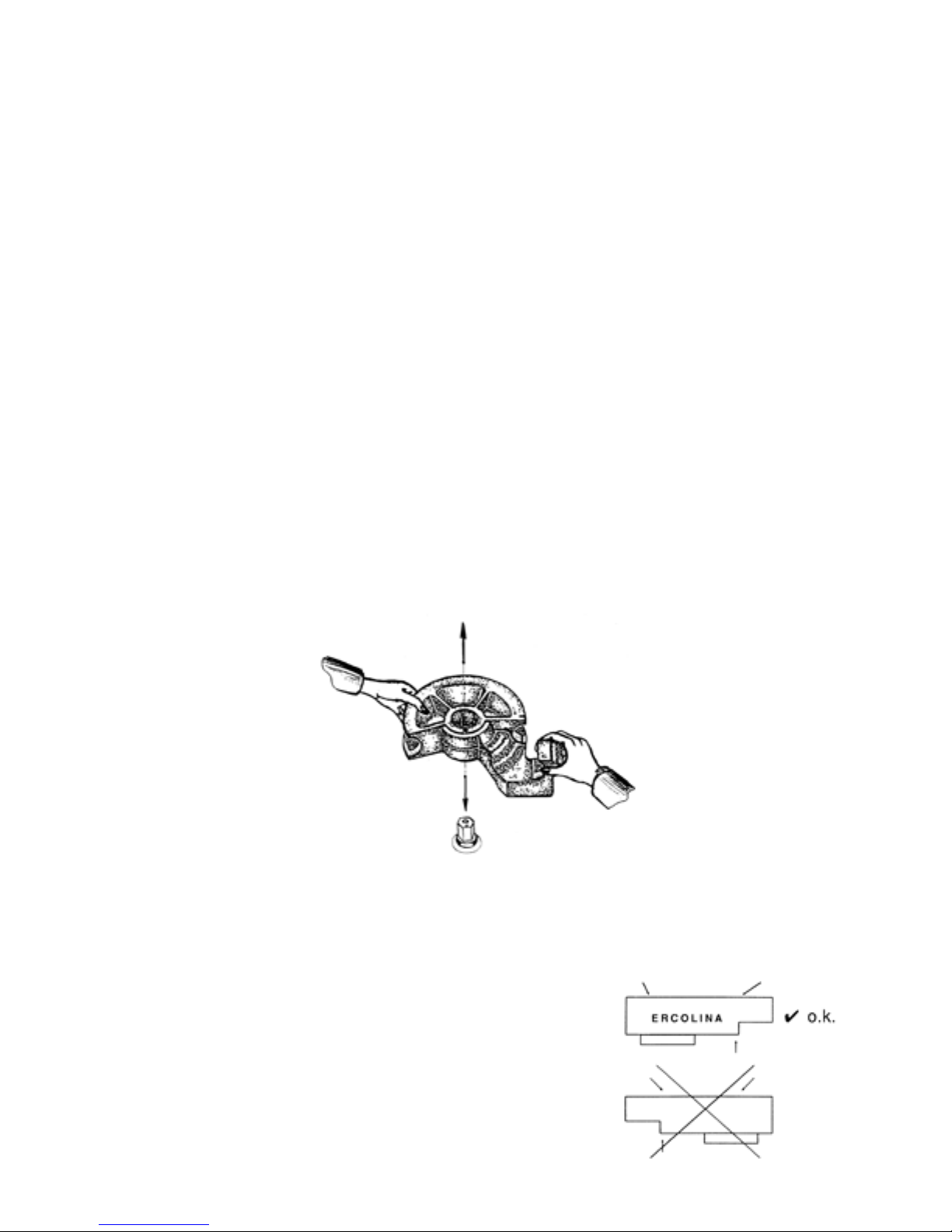
Ercolina® center formers are manufactured with an offset hex design ensuring proper installation. When
mounted, the center former’s gripper arm should face right side of machine.
- Mounting counterbending die -
Ercolina® counterbending dies are designed for quick installation and removal. Insert male dovetail located
on back of counterbend die into slot on counterbending die vise. Hold die rmly against vise, depress and
rotate black knob clockwise securing die onto vise bracket. Installed properly, the “Ercolina®” logo will be
facing the operator (see gure). Note: When bending heavy wall proles and solids, standard counterbend
die and vise must be removed and replaced with a roller counterbend die. Attention: Failure to use roller
style die on heavy proles may result in machine damage. (See Mounting “roller” counterbending die
instructions.)
Note: Counterbending dies are wear items - Replace as
necessary to insure bend quality. Counterbending die
should never contact center former when material is in
former and tooling is in starting position.
-8-
Page 9
- Mounting “roller” counterbending die -
When bending heavy wall proles or solid materials a roller counterbending die must be used. Remove
counterbend die vise assembly and place roller die onto tool post. With material in center former advance
roller die inward until material rests rmly between former and roller. Retract roller die approximately 1½″ to
2″ from material. Warning: Never use roller die ush against material.
- Counterbending die lubrication -
For best results counterbending dies should be kept lubricated with Ercolina® spray grease - Part # 810.
Proper lubrication extends counterbend die life and improves bend quality.
- Loading workpiece -
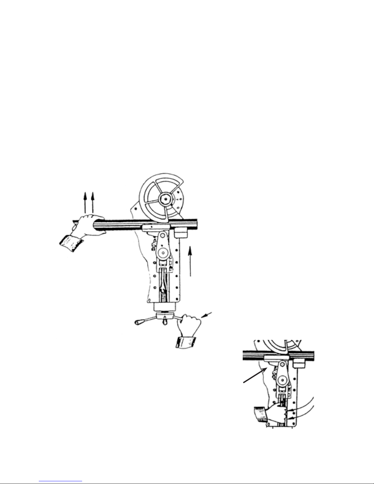
1. Slide workpiece into gripper arm and groove of center former
2. Using hand wheel advance counterbending die forward until material rests securely between former
and die (see FIG. 1).
3. Properly adjusted vise and counterbending die assembly should be perpendicular to workpiece and
swing freely counterclockwise to release workpiece (see FIG. 2).
Note: If vise assembly pivots away from material at beginning of bend, reduce pressure on vise. Proper
counterbending die adjustment insures satisfactory bends.
(FIG. 1)
(FIG. 2)
-9-
Page 10
Mega Bender®
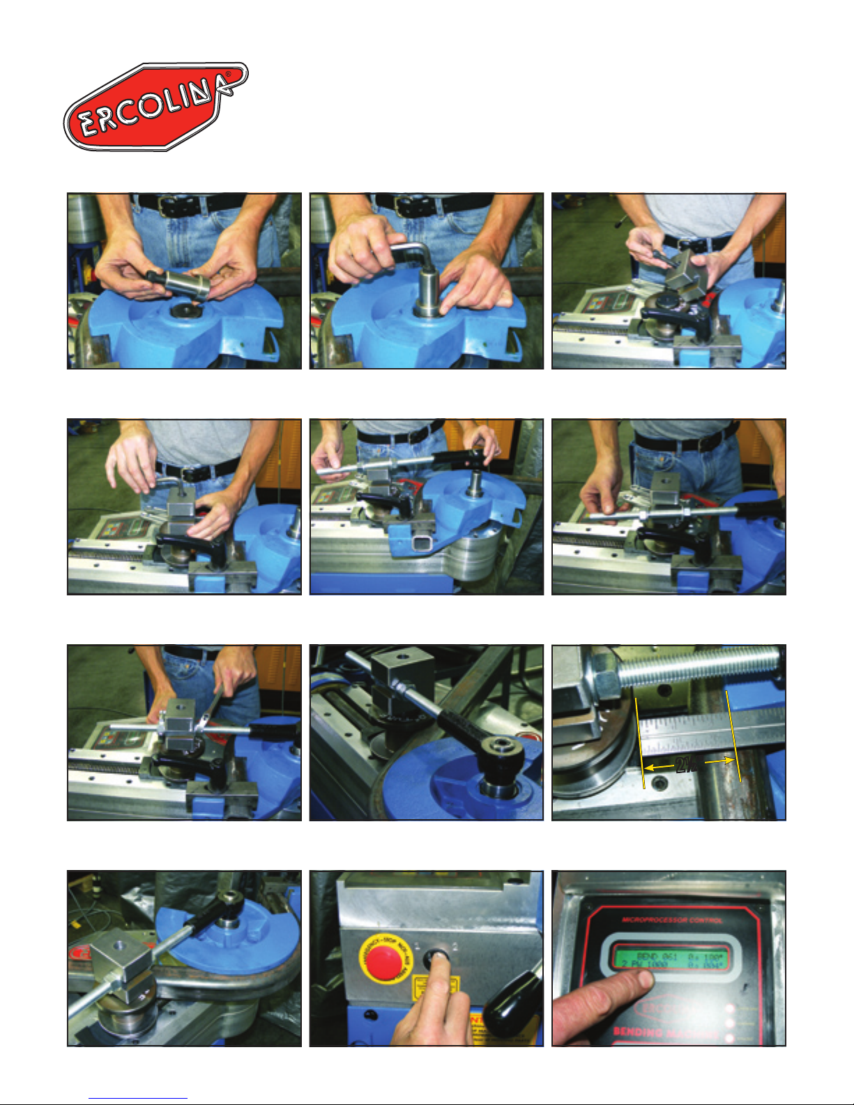
ERCOLINA® ROTARY DRAW
TIE BAR ACCESSORY
030, TB76, TB60, 050KD, SB48 and 060 Super Bender
®
Hex Drive Center Pivot
Securing Saddle Block
Securing Centerformer
Pivot Shaft
Installing Tie Bar Side Loading Tie Bar
Saddle Block Mounting Screw
2½″2½″
Tie Bar Nuts
Tie Bar Assembly
Tie Bar Assembly Mounted Minimum Distance (g. 1)
-10-
Speed Selector PW Reading
Page 11
- Mounting “roller” counterbending die -
When bending heavy wall proles or solid materials a roller counterbending die must be used. Remove
counterbend die vise assembly and place roller die onto machine tool post. With material in center former
advance roller die inward until material rests rmly between former and roller. Retract roller die approximately
2½″ from material (refer to g. 1 on page 10). Warning: Never use roller die ush against material
– doing so will damage machine.
Special Application Tooling – Part# 030TIEBAR
● Never bend material exceeding machine specications (i.e. high tensile,
stainless, heavy prole or solid). Contact factory for machine capacity
before bending.
● Always use lowest rpm setting. Reset tool shaft position – “C” axis 10° above
“0” home – to avoid center former interference with machine case.
● Always use roller-style counterbending die.
● Mounting the roller-style counter bending die (Heavy Proles or Solids). Heavy
wall proles and solid materials require a roller counterbending die. Remove
the standard counterbend die vise assembly and slide roller onto vise mounting post. With material in former move roller die inward until material rests
rmly between former and roller. Back roller die off approximately 2½″.
Warning: Never use roller die rmly against the material.
● Always use tie bar. Refer to mounting instructions. Tighten hex nuts neutrally, neither pushing nor pulling against tie bar assembly. Rotate hand wheel
counter clockwise to remove play from counterbending vise screw.
● Always use lubrication on roller-style counterbending die and tool post.
● When bending – monitor machine display for PW or Amp reading. Never
exceed 1200 PW/12 Amp.
-11-
Page 12

Bender Programming
- Control panel functions -
Display and Switches Function
Left two switches and display Springback setting
Middle three switches and display Bend angle adjustable 0-180 degrees
Right one switch and display Slow down setting
- Enter bend angle -
Rotate the bend angle selector switch to desired bend angle.
- Determining springback setting -
With all previous steps completed, material and tooling in the bending position, begin bend cycle by
holding bend switch or depressing foot pedal until the material begins to ex and stop. Observe the
degree reading on the display.
- Entering springback value -
Rotate the springback selector switch to desired setting. Adjust as necessary to achieve desired bend
angle. When programming angles less than the springback value adjust this setting to zero and increase
the bend angle as necessary.
- Entering slow down setting -
Adjust end of bend slow down setting as follows:
Tube Diameter ........... .250″ – 1.000″ ..........3
Tube Diameter ......... 1.000″ – 1.375″ ..........2
Tube Diameter ......... 1.375″ – 1.625″ ..........1
Tube Diameter ......... 1.625″ – 2.000″ ..........0
- Adjusting countering bending die support screw -
Use provided T-handle Allen wrench, and turn adjustment screw until it contacts the backside of the vise.
Secure screw with locking jam nut. This adjustment screw affects the quality of the bend and must be set
each time the material prole and or size are changed.
- Finishing bend -
Hold bend switch or depress the foot pedal and hold, the Top Bender© will automatically stop at
programmed angle.
- Return center former to zero position -
Hold bend switch or depress foot pedal and hold until bender stops at the zero position.
- Editing bend angle and springback values -
The bend angle and springback settings can be edited at any time during the forward bending cycle by
rotating the selector switches to the desired setting.
- Initial springback setup -
1. With previous steps completed -
2. Initiate bend cycle by depressing foot pedal switch
3. Stop bend cycle when material begins to deect (see FIG. 1)
4. Observe degree reading on control panel.
5. Rotate springback selector switch to input springback value into program (Note: Springback value
can be edited later if needed). Springback must be set for each angle.
-12-
Page 13
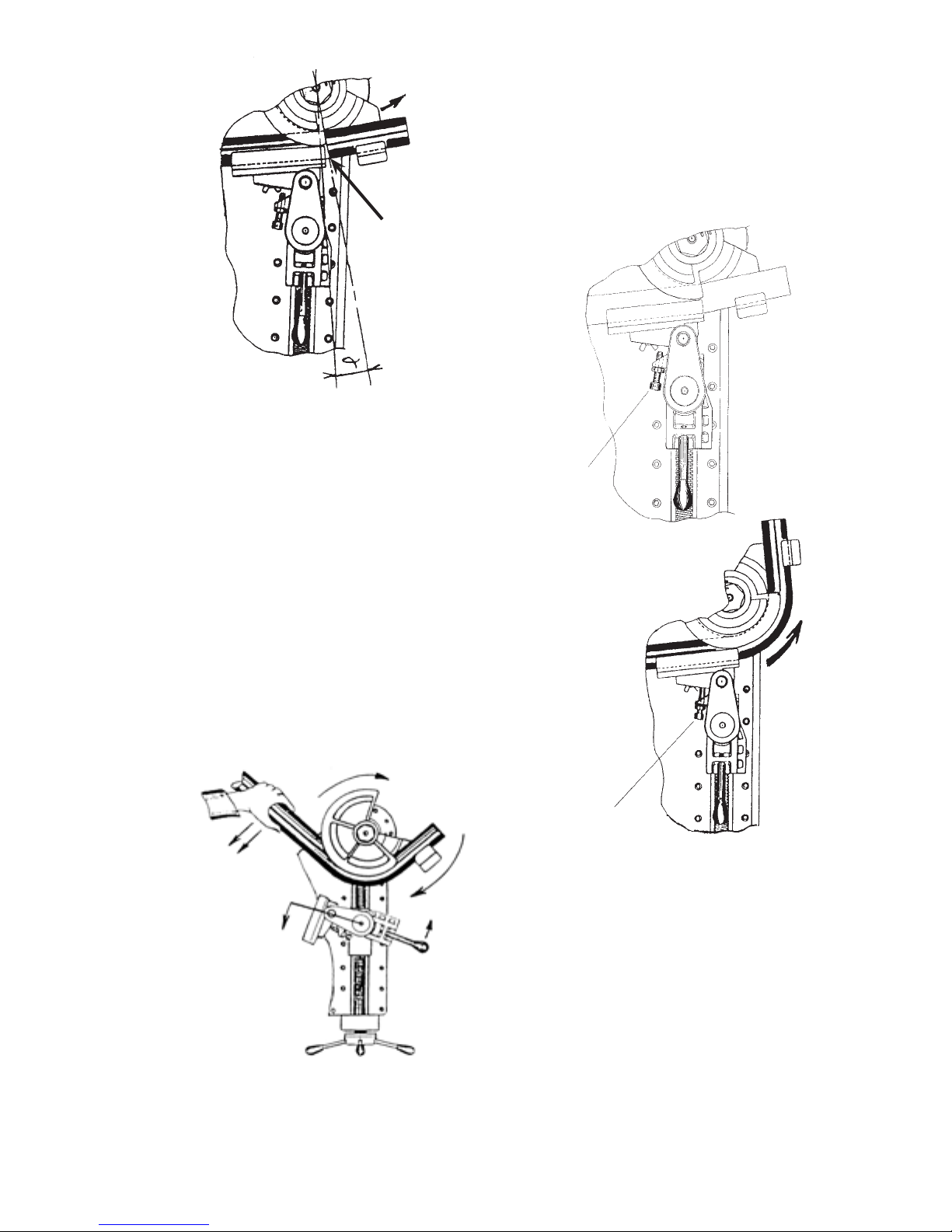
(FIG. 1)
Pipe deected
from straight
position
- Adjusting counterbending die support screw -
Using Allen wrench, turn adjustment screw until
contacting back side of vise. Secure screw with
locking jam nut (see FIG. 2). Adjustment screw
affects quality of bend and must be set for each material.
(FIG. 2)
ADJUSTMENT
SCREW
HOW TO USE THE ADJUSTMENT SCREW
- Finishing bend -
Hold bend switch or depress and hold foot pedal
completing bend cycle (see FIG. 3).
- Return center former to “0” position -
Hold bend switch or depress return foot pedal until bender
returns to “0” home position (see FIG. 4).
(FIG. 4)
ADJUSTMENT
SCREW
(FIG. 3)
- Editing bend angles and springback values -
Bend angles and springback values can be edited at any time during a bend cycle using rotary switches on
control board.
-13-
Page 14
Bending Troubleshooting
Problem Probable Cause Solution
Material wrinkles or deforms Counterbend die pressure incorrect Increase counter die pressure
Radii too small for prole Increase CLR of tooling
Tube slips Poor quality tubing Conrm tubing measurements and
replace with quality material
Counterbend die pressure is too low Increase die pressure tension
Material cracks or breaks Material quality poor Conrm material composition
with mill certications
Poor bend quality Material quality poor Replace material
CLR too small for prole Increase tooling CLR
Improper tooling adjustment Reset counterbend die pressure
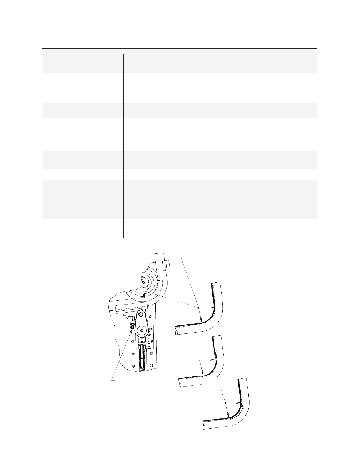
Workpiece ends are oval or Too much pressure on die Decrease die pressure, change
deformed adjustment screw setting (see g. below)
Machine overloads Material exceeds machine’s capacity Reduce material size or wall thickness
Counterbend die wears Excessive pressure on Decrease counterbend die pressure
prematurely counterbend die
Lack of lubrication Use Ercolina® bending lubricant
Material dirty or rusted Replace material or clean surface
Tube has marks Poor tube quality Replace material
Tooling not ordered for material Consult factory
Improvement of bend quality
achieved by ne adjustment
of adjustment screw
Results achieved
after bending
without adjustment
screw or by using it
in a too backward
position
Adjustment screw
Results achieved after bending
without adjustment screw or by
using it in a too forward position
-14-
Page 15
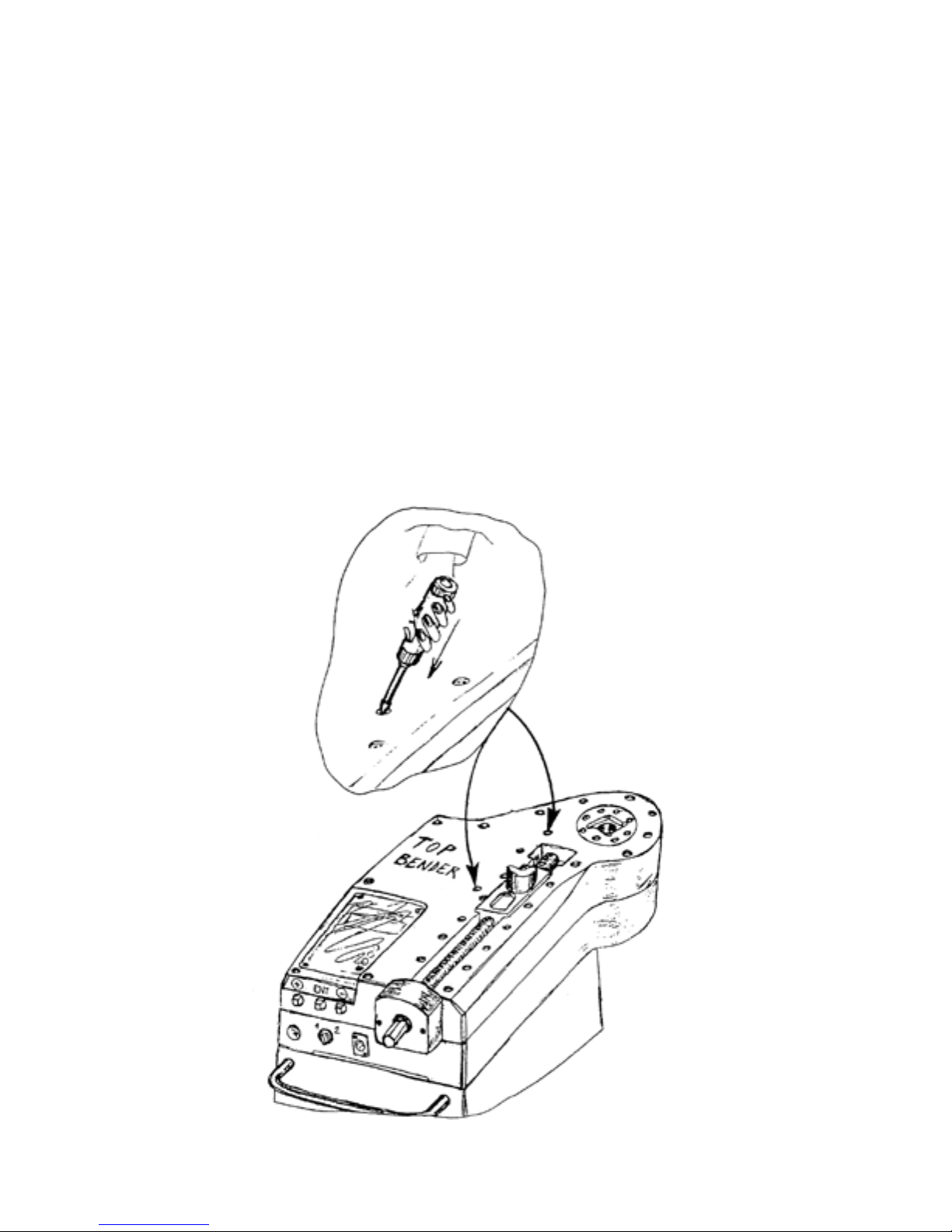
- 060® Super Bender® Accessories -
A40/P - Two axis positioning table
Polymer counterbending die
O50M - Mechanical tube and pipe positioner
Folding/Bending attachment
O50E - Counterbending die support bracket for radii 225mm
O50I - ⅜″ - 2½″
O50J - 2½″ - 3″
810 - One 12-oz can of Ercolina® Spray Grease
811 - 9pc case of Ercolina® Spray Grease
- Routine Maintenance -
Keep machine clean and free of grease and debris
Using supplied grease gun, lubricate gearbox at zirts every 40 hours of use (see gure)
Replace worn power cords or broken switches
Clean encoder with electrical contact cleaner or canned air spray
Any repair or replacement of internal or external parts of machine must be made only by personnel
trained/authorized by Ercolina
Replace worn tooling
Ercolina® reserves the right not to supply accessories or spare parts if machine has been modied
®
-15-
Page 16

Troubleshooting
Problem Probable Cause Solution
Machine doesn’t turn on Electrical connections Check power source and plug end
Emergency switch depressed Release emergency switch
Fuse blown Replace fuse
Stops and display ashes Overload, refer to machine capacity Turn machine off, depress the blue
chart reset button, turn machine on
Depress foot pedal and machine No bend angle stored Program machine
will not start
Counter miscounts Encoder or star wheel dirty or Clean with CRC electrical cleaner
defective
-16-
Page 17
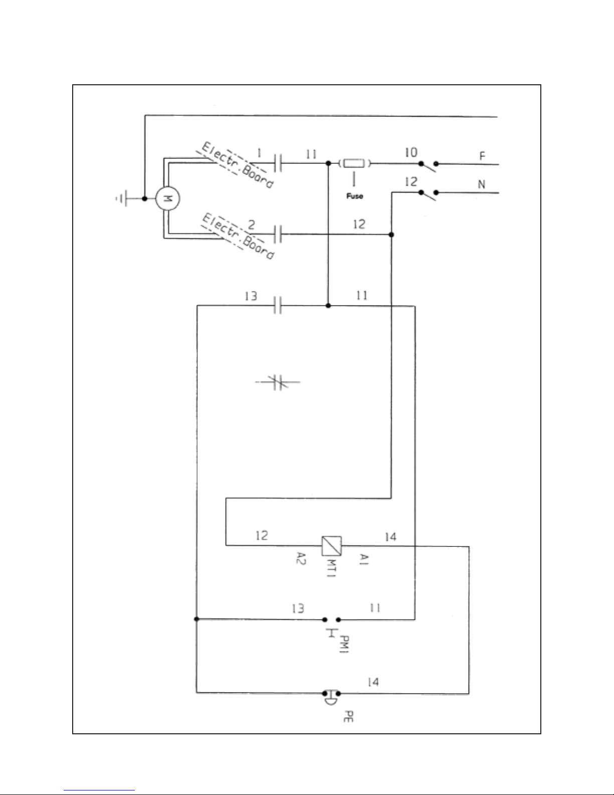
Electrical Schematic (220V)
110 / 220 Volts A.C.
WIRING DIAGRAM - SUPER BENDER A – SUPER BENDER B
Art. 060A & 060B
-17-
Page 18
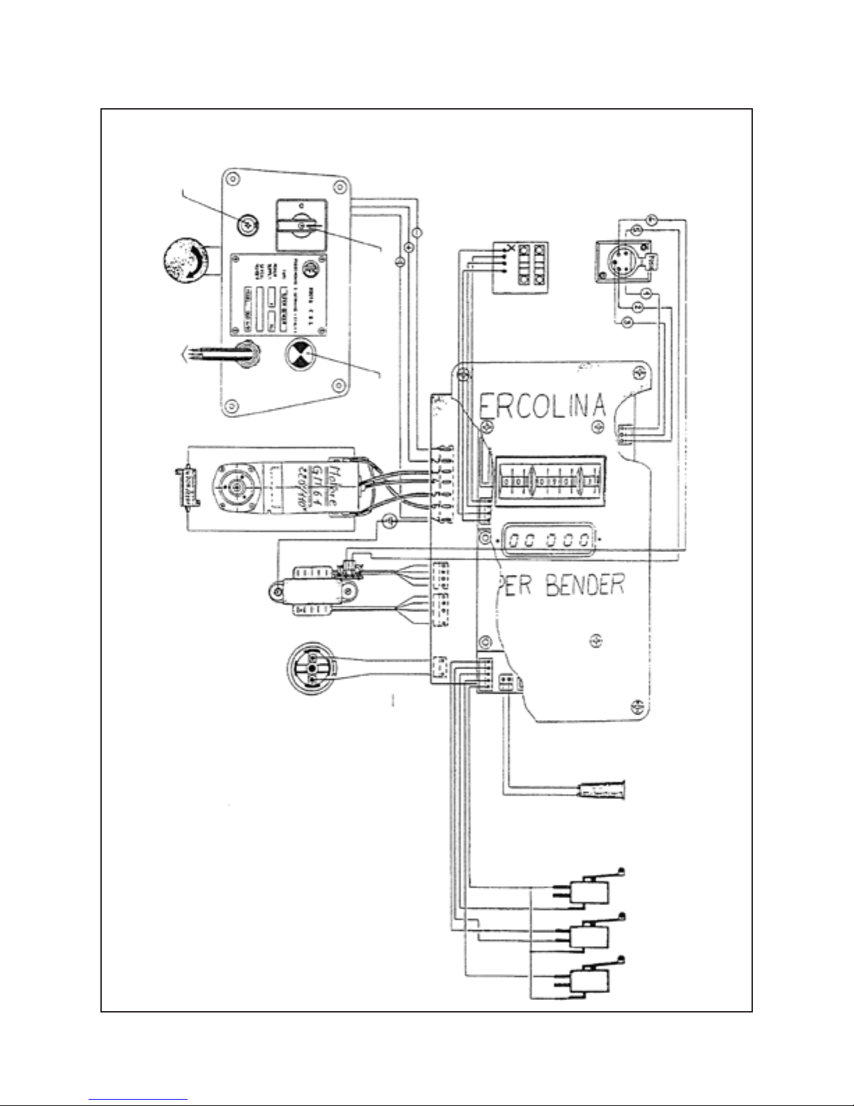
(Max 16A 110V)
Emergency
stop
Power cable
Brush resistor
Fuse
(Max 8A 220V)
Wiring Diagram
Power switch
Blue power
reset button
encoder
reader
Degree
Pedal
socket
WIRING DIAGRAM - SUPER BENDER Art. 060 A & B
220 or 110 V a.c.
Transformer
Dynamo
Fuse holder
card
Blue
Yellow
Gray
Green
Blue
White
Blue
Bend
Ret.
S.D.
Magnetic
switch
Microswitches
-18-
Page 19
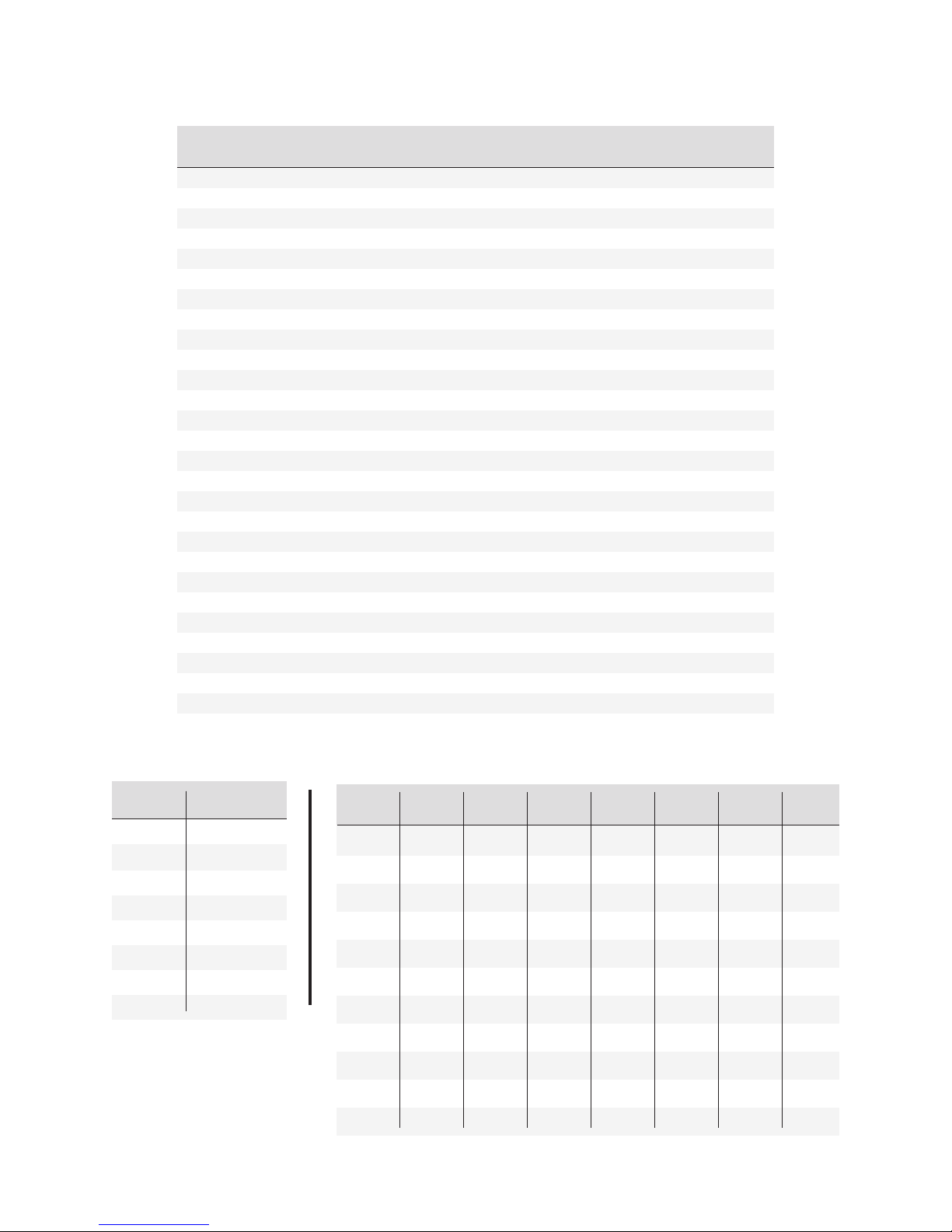
Material Length Required for Rotary Bends in Pipe
“Guideline for material consumption.”
Bend ½ with ¾ with 1 with 1¼ with 1½ with 2 with
Angle 1.8 CLR 2.2 CLR 2.6 CLR 3.5 CLR 3.9 CLR 5.9 CLR
5 .16 .19 .23 .31 .34 .52
10 .31 .38 .45 .61 .68 1.03
15 .47 .58 .68 .92 1.02 1.55
20 .63 .77 .91 1.22 1.36 2.07
25 .79 .96 1.13 1.53 1.70 2.58
30 .94 1.15 1.36 1.83 2.04 3.10
35 1.10 1.34 1.59 2.14 2.38 3.61
40 1.26 1.54 1.82 2.44 2.72 4.13
45 1.41 1.73 2.04 2.75 3.06 4.65
50 1.57 1.92 2.27 3.05 3.40 5.16
55 1.73 2.11 2.50 3.36 3.74 5.68
60 1.88 2.30 2.72 3.67 4.08 6.20
65 2.04 2.50 2.95 3.97 4.42 6.71
70 2.20 2.69 3.18 4.28 4.76 7.23
75 2.36 2.88 3.40 4.58 5.11 7.74
80 2.51 3.07 3.63 4.89 5.45 8.26
85 2.67 3.26 3.86 5.19 5.79 8.78
90 2.83 3.46 4.08 5.50 6.13 9.29
100 3.14 3.84 4.54 6.11 6.81 10.33
110 3.46 4.22 4.99 6.72 7.49 11.36
120 3.77 4.61 5.45 7.33 8.17 12.39
130 4.08 4.99 5.90 7.94 8.85 13.42
140 4.40 5.38 6.35 8.55 9.53 14.46
150 4.71 5.76 6.81 9.16 10.21 15.49
160 5.03 6.14 7.26 9.77 10.89 16.52
170 5.34 6.53 7.71 10.38 11.57 17.55
180 5.65 6.91 8.17 11.00 12.25 18.59
To calculate total pipe length, add distance from end of pipe to the rst bend, plus rst bend arc length, plus distance to second bend
Commercial pipe and wall thickness
Tube Equivalent
gauge in inches
10 .134
11 .120
12 .109
13 .095
14 .083
16 .065
18 .049
20 .035
Nominal Outside Schedule Schedule Schedule Schedule Schedule XX
Size Dia. 5 10 40 80 160 Strong
⅛ .405 .049 .068 .095
¼ .540 .065 .088 .119
⅜ .675 .065 .091 .126
½ .840 .065 .083 .109 .147 .188 .294
¾ 1.050 .065 .083 .113 .154 .219 .308
1 1.315 .065 .109 .133 .179 .250 .358
1¼ 1.660 .065 .109 .140 .191 .250 .382
1½ 1.900 .065 .109 .145 .200 .281 .400
2 2.375 .065 .109 .154 .218 .344 .436
2½ 2.875 .083 .120 .203 .276 .375 .552
3 3.500 .083 .120 .216 .300 .438 .600
-19-
Page 20

0.516 13.096
0.531 13.493
0.547 13.890
0.578 14.684
0.594 15.081
0.609 15.478
0.641 16.271
0.656 16.668
0.672 17.065
0.703 17.859
0.719 18.256
64
⁄
33
0.563 14.287
32
64
64
32
64
16
⁄
⁄
⁄
⁄
⁄
9
17
35
37
19
64
⁄
⁄
39
41
0.688 17.462
32
64
16
⁄
⁄
⁄
11
21
43
0.734 18.653
64
32
64
⁄
⁄
⁄
45
23
47
Inches to Millimeters Conversion
0.203 5.159
0.234 5.953
0.219 5.556
64
64
32
⁄
⁄
⁄
7
13
15
¼ 0.250 6.350 ¾ 0.750 19.049
Fractions Decimal MM Fractions Decimal MM
0.016 0.397
0.031 0.794
0.047 1.191
0.063 1.588
0.078 1.984
0.094 2.381
64
32
64
⁄
1
16
⁄
⁄
⁄
1
3
1
0.109 2.778
64
32
64
⁄
⁄
⁄
5
3
7
⅛ 0.125 3.175 ⅝ 0.625 15.874
0.172 4.366
0.141 3.572
0.156 3.969
0.188 4.763
64
64
32
16
⁄
⁄
⁄
9
⁄
5
3
11
0.766 19.446
0.781 19.843
64
32
⁄
⁄
49
25
0.266 6.744
0.281 7.144
64
32
⁄
⁄
9
17
0.797 20.240
0.813 20.637
64
16
⁄
⁄
51
13
0.297 7.541
0.313 7.938
64
16
⁄
⁄
5
19
0.828 21.034
0.844 21.431
64
32
⁄
⁄
53
27
0.328 8.334
0.344 8.731
64
32
⁄
⁄
11
21
0.859 21.828
64
⁄
55
0.360 9.128
64
⁄
23
⅜ 0.375 9.525 ⅞ 0.875 22.224
0.891 22.621
0.906 23.018
64
32
⁄
⁄
57
29
0.391 9.922
0.406 10.319
64
32
⁄
⁄
25
13
0.922 23.415
0.938 23.812
64
16
⁄
⁄
59
15
0.422 10.716
0.438 11.113
64
16
⁄
⁄
7
27
0.953 24.209
64
⁄
61
31
0.453 11.509
64
⁄
29
15
0.969 24.606
0.984 25.003
32
64
⁄
⁄
63
0.469 11.906
0.484 12.303
32
64
⁄
⁄
31
½ 0.500 12.700 1 1.000 25.399
Millimeters to Inches Conversion
MM Inches MM Inches MM Inches MM Inches
Decimal Decimal Decimal Decimal
1 0.039 29 1.141 57 2.244 85 3.347
2 0.079 30 1.181 58 2.284 86 3.386
3 0.118 31 1.221 59 2.323 87 3.425
4 0.158 32 1.260 60 2.362 88 3.465
5 0.197 33 1.299 61 2.402 89 3.504
6 0.236 34 1.339 62 2.441 90 3.543
7 0.276 35 1.378 63 2.480 91 3.583
8 0.315 36 1.417 64 2.520 92 3.622
9 0.354 37 1.457 65 2.559 93 3.661
10 0.394 38 1.496 66 2.598 94 3.701
11 0.433 39 1.535 67 2.638 95 3.740
-20-
12 0.472 40 1.575 68 2.677 96 3.780
13 0.512 41 1.614 69 2.717 97 3.819
14 0.551 42 1.654 70 2.756 98 3.858
15 0.591 43 1.693 71 2.795 99 3.898
16 0.630 44 1.732 72 2.835 100 3.937
17 0.669 45 1.772 73 2.874 110 4.331
18 0.709 46 1.811 74 2.913 120 4.724
19 0.748 47 1.850 75 2.953 130 5.118
20 0.787 48 1.890 76 2.992 140 5.512
21 0.827 49 1.929 77 3.032 150 5.906
22 0.866 50 1.969 78 3.071 160 6.299
23 0.906 51 2.008 79 3.110 170 6.693
24 0.945 52 2.047 80 3.150 180 7.087
25 0.984 53 2.087 81 3.189 190 7.480
26 1.024 54 2.126 82 3.228 200 7.874
27 1.063 55 2.165 83 3.268 250 9.843
28 1.102 56 2.205 84 3.307 300 11.811
Page 21
Minimum Distance Between Bends
By Center Line Radius
Radius of Minimum Distance
Center Former Between Bends
Inches Metric Inches Metric
.394 10 NA NA
.472 12 NA NA
.591 15 NA NA
.630 16 NA NA
.709 18 NA NA
.787 20 NA NA
.945 24 NA NA
1.023 26 NA NA
1.102 28 NA NA
1.181 30 NA NA
1.259 32 NA NA
1.417 36 2.362 60
1.811 46 3.149 80
2.204 56 3.740 95
2.637 67 3.937 100
3.228 82 3.937 100
3.543 90 4.330 110
3.937 100 4.330 110
4.133 105 4.330 110
4.409 112 4.330 110
4.724 120 5.511 140
5.118 130 5.511 140
5.708 145 5.905 150
6.692 170 5.905 150
7.283 185 5.905 150
7.480 190 5.905 150
8.858 225 5.905 150
10.236 260 6.299 160
11.811 300 6.299 160
Super Bender® with pipe kit Super Bender® with tube kit
Min. Min.
Size CLR Former part # Counterbend # Size CLR Former part # Counterbend #
Wall Wall
½″ 1.8 .109 153R046P0500 155P0500 ¾″ 2.6 .039 153R067T0750 154T0750
¾″ 2.2 .113 153R056P0750 155P0750 ⅞″ 2.6 .039 153R067T0875 154T0875
1″ 2.6 .133 153R067P1000 155P1000 1″ 3.2 .039 153R082T1000 154T1000
1¼″ 3.5 .140 153R090P1250 155P1250 1¼″ 4.4 .039 153R112T1250 154T1250
1½″ 3.9 .145 153R100P1500 155P1500 1½″ 5.9 .047 153R150T1500 154T1500
1¾″ 6.7 .059 153R170T1750 154T1750
Pipe kit only # PIPEKIT2 Tube kit only # TUBEKIT2
-21-
 Loading...