

Page 1
L’esprit Modem
User Guide
GenIP 30i
Reference: EG_GenIP30i_1016_UG_004_UK
Revision: 004
Date: 10/11/2015
http://www.ercogener.com
Dct_427_02
Page 2

Document History
Rev. Modifications Author Date Validation Date
000 CREATION YST 10/05/2012 LGO 14/05/2012
§ 3.2.1.2 Screw connectors and § 6.7 Input /
Output Interface la pin 19 O4-is actually O3-
§ 5.2.1.1 Definition of course of actions in a
scrip adding this paragraph.
§ 5.2.3.1 Management of characters in the
buffer
§ 5.2.6 Macro Commands update the
presentation, adding macros.
§ 5.2.7 Dynamic messages update the
message list.
§ 5.2.8.2 Sequence of script adding an
application example.
§ 5.2.16.1 Connect disconnect WAN link in the
001
002
003
004
The main modifications of this document compared to the previous version are easily identifiable on the
screen by the blue color of the text.
script adding this paragraph.
§ 5.2.26 Hardware Option adding this
paragraph.
§ 5.2.27 Inactivity Timer adding this paragraph.
§ 5.3.2.3 Format of data and number of
registers that can be read Adding parameter
INVERTED.
§ 5.3.7 Addressable memory of the GenIp
modification updating the address space.
§ 6.8 External Supply V
and § 7.2.7 External
O
power supply VO uploading the limitation of
the output V
.
O
§ 7.2.5.2 Analog Inputs in current (0-25mA)
adding information on the conversion range.
§8.1 General security added used precaution
Fixed dialing paragraph
§5.2.5 Add macro Command
§5.2.7.1 to 5.2.7.3 Dynamics messages
§ 5.2.8.2 Default value script number
§ 5.2.9.1 Integrate address 132.xxx.xxx.xxx
§5.2.15 Setting GSM CSD
Update screen shot ModBus
§ 5.3.2.1 ModBus Structure
Update comsumption § 7.2 Electrical
characteristics
Add
§ 5.4 Information on SNMP function
§ 7.2.8 Output Input and External Power
supply behavior
Add
§ 5.2.6 Macro command reset modem
§ 5.2.8 PHP language
§ 5.2.24 IPsec Tunnel
§ 5.2.25.1 Chart used
§ 7.2.5.1Analog Inputs in Voltage (0-25V
§ 7.2.5.2 Analog Inputs in current (0-25mA
§ 7.2.6.2 Add scheme Output active
YST 03/05/2013 LGO 03/05/2013
LGO
YST
26/03/2014 YST 14/10/2014
LGO 22/10/2014 YST 24/10/2014
LGO 21/10/2015 YST 10/11/2014
http://www.ercogener.com
Dct_427_02
Page 3

EG_GenIP30i_1016_UG_004_UK Page 3 / 143
TABLE OF CONTENTS
PRESENTATION ............................................................................................................................................... 8
WARNING ......................................................................................................................................................... 9
COPYRIGHT ................................................................................................................................................... 10
1 REFERENCES........................................................................................................................................ 11
1.1 REFERRED DOCUMENTS .................................................................................................................... 11
1.2 ABBREVIATIONS ............................................................................................................................... 11
1.3 SYMBOLS ......................................................................................................................................... 13
2 PACKAGING .......................................................................................................................................... 14
2.1 CONTENT ......................................................................................................................................... 14
2.2 PACKING CASE ................................................................................................................................. 14
2.3 MODEM LABELS ............................................................................................................................... 15
3 GENERAL PRESENTATION ................................................................................................................. 16
3.1 DESCRIPTION ................................................................................................................................... 16
3.2 EXTERNAL CONNECTIONS ................................................................................................................. 17
3.2.1 Connections ............................................................................................................................. 17
3.2.1.1 Antenna connector .......................................................................................................... 17
3.2.1.2 Screw connectors ........................................................................................................... 17
3.2.1.3 Sub D 9-pin connector .................................................................................................... 18
3.2.1.4 RJ45 Ethernet LAN connector ....................................................................................... 18
3.2.1.5 USB connectors .............................................................................................................. 19
3.2.1.6 Reset Button .................................................................................................................... 19
3.2.2 Accessories supplied .............................................................................................................. 20
3.2.2.1 Straight cable 9pin M/F ................................................................................................... 20
3.2.2.2 Ethernet RJ45 straight cable .......................................................................................... 21
3.2.2.3 GSM hinged antenna (SMA-M) ....................................................................................... 21
4 TECHNICAL CHARACTERISTICS AND OPTIONS .............................................................................. 22
4.1 TECHNICAL CHARACTERISTICS .......................................................................................................... 22
4.2 ACCESSORIES AND OPTIONS ............................................................................................................ 23
4.3 BACKUP BATTERY ............................................................................................................................ 23
4.3.1 Characteristics of the battery ................................................................................................. 23
5 USING THE GENIP 30I .......................................................................................................................... 24
5.1 STARTING WITH THE GENIP 30I ......................................................................................................... 24
5.1.1 Assembling and disassembling the GenIP 30i ..................................................................... 24
5.1.2 SIM card Access ...................................................................................................................... 25
5.1.2.1 Insertion Carte SIM.......................................................................................................... 25
5.1.2.2 SIM card Removal ........................................................................................................... 25
Descriptions and non-contractual illustrations in this document are given as an indication only.
ERCOGENER reserves the right to make any modifications.
Dct_427_02
Page 4

5.1.3
Installation of the GenIP 30i .................................................................................................... 26
EG_GenIP30i_1016_UG_004_UK Page 4 / 143
5.1.4 Using the GenIP 30i with the browser ................................................................................... 27
5.2 BASIC PRINCIPLE .............................................................................................................................. 32
5.2.1 Actions ...................................................................................................................................... 32
5.2.1.1 Definition of course of actions in a script .................................................................... 32
5.2.1.2 Pilot an action in DTMF .................................................................................................. 33
5.2.2 Events ....................................................................................................................................... 34
5.2.2.1 Planning events ............................................................................................................... 34
5.2.3 Pattern ....................................................................................................................................... 36
5.2.3.1 Management of characters in the buffer ....................................................................... 36
5.2.4 Acknowledgements ................................................................................................................. 37
5.2.4.1 Acknowledgement via Macro Command ...................................................................... 37
5.2.4.2 Acknowledgement via DTMF ......................................................................................... 38
5.2.5 Remarks about syntax of acknowledgements, Macro Commands, patterns or frames
received upon action starting .............................................................................................................. 39
5.2.5.1 Reaction of the GenIP 30i in case of authorized sources and syntax error.............. 39
5.2.6 Macro Commands .................................................................................................................... 40
5.2.7 Dynamic messages .................................................................................................................. 54
5.2.7.1 Identifications and states messages ............................................................................. 54
5.2.7.2 Systems messages ......................................................................................................... 55
5.2.7.3 Users messages .............................................................................................................. 57
5.2.8 Script ......................................................................................................................................... 59
5.2.8.1 Creation of a script in GenIP language ......................................................................... 59
5.2.8.2 Creation of a script in PHP language ............................................................................ 62
5.2.8.2.1 Header function dedicaded to GenIP ....................................................................... 62
5.2.8.3 Sequence of script .......................................................................................................... 63
5.2.9 IP Information ........................................................................................................................... 65
5.2.9.1 LAN IP Address managed by the GenIP 30i ................................................................. 65
5.2.9.2 GenIP 30i in DHCP server ............................................................................................... 65
5.2.9.3 GenIP 30i as Client DHCP ............................................................................................... 65
5.2.9.4 Definition of Masquerade ............................................................................................... 66
5.2.9.5 Ports management .......................................................................................................... 66
5.2.9.6 Incoming PPP connection .............................................................................................. 66
5.2.9.7 Outgoing PPP connection .............................................................................................. 66
5.2.10 Time out of connection and disconnection on TCP service ........................................... 67
5.2.11 PIN code and SIM card management ................................................................................ 67
5.2.12 Reloading a configuration from a backup file .................................................................. 67
5.2.13 Notes about the definition and the behavior of the actions ............................................ 68
5.2.14 Loss and recovering of network (LAN) ............................................................................. 68
5.2.15 Remarks about GSM/WAN/SMS connections ................................................................... 69
5.2.16 Remarks of WAN connection disconnection of the GenIP 30i ....................................... 69
5.2.16.1 Connect disconnect WAN link in the script ................................................................. 70
5.2.17 Remarks concerning the clock management ................................................................... 70
Descriptions and non-contractual illustrations in this document are given as an indication only.
ERCOGENER reserves the right to make any modifications.
Dct_427_02
Page 5

5.2.18
Remarks concerning the management of the network gateway or LAN ....................... 70
EG_GenIP30i_1016_UG_004_UK Page 5 / 143
5.2.19 Remarks concerning the management of the DNS service ............................................ 71
5.2.20 Remarks concerning the tools ........................................................................................... 71
5.2.20.1 Bytes meter ...................................................................................................................... 71
5.2.20.2 Modem commands tracks .............................................................................................. 71
5.2.20.3 System log tracks............................................................................................................ 72
5.2.21 Remarks concerning Allowed sources ............................................................................. 72
5.2.21.1 Unwanted connections BlackList .................................................................................. 72
5.2.22 Remarks about tunnels ....................................................................................................... 72
5.2.22.1 SSL Tunnel ....................................................................................................................... 73
5.2.23 Data Logging ........................................................................................................................ 74
5.2.24 IPSec Tunnel ........................................................................................................................ 74
5.2.25 User Management and Password ...................................................................................... 75
5.2.25.1 Creating a User ................................................................................................................ 75
5.2.25.2 Change Password ........................................................................................................... 76
5.2.25.3 Hierarchy .......................................................................................................................... 76
5.2.26 Remarks about the function Bridge .................................................................................. 78
5.2.27 Hardware Option .................................................................................................................. 78
5.2.28 Inactivity Timer .................................................................................................................... 79
5.3 INFORMATION ABOUT THE FUNCTION MODBUS ................................................................................... 80
5.3.1 Configuration ........................................................................................................................... 82
5.3.2 Modbus Master ......................................................................................................................... 85
5.3.2.1 Structure of the messages Modbus Master ................................................................. 85
5.3.2.2 Function Code authorized .............................................................................................. 86
5.3.2.3 Format of data and number of registers that can be read .......................................... 87
5.3.2.4 Example of use of a variable .......................................................................................... 88
5.3.3 Structure of messages Modbus RTU ..................................................................................... 91
5.3.4 Structure of messages Modbus TCP ..................................................................................... 92
5.3.5 Functions codes of the Modbus standards supported ........................................................ 92
5.3.5.1 Reading of N bits of output ............................................................................................ 92
5.3.5.2 Reading of N bits of input .............................................................................................. 93
5.3.5.3 Reading of N registers of exploitation .......................................................................... 93
5.3.5.4 Reading of N registers of input ...................................................................................... 94
5.3.5.5 Writing of 1 bit of output ................................................................................................ 94
5.3.5.6 Writing of 1 register of exploitation ............................................................................... 94
5.3.5.7 Writing of N bit of output ................................................................................................ 95
5.3.5.8 Writing of N registers of exploitation ............................................................................ 96
5.3.6 Error codes Modbus ................................................................................................................ 97
5.3.7 Addressable memory of the GenIp ........................................................................................ 98
5.3.8 Register of configuration ........................................................................................................ 99
5.3.9 Reading of digital inputs ....................................................................................................... 100
5.3.10 Inputs of counting ............................................................................................................. 101
5.3.11 Reading/Writing of digital outputs ................................................................................... 102
Descriptions and non-contractual illustrations in this document are given as an indication only.
ERCOGENER reserves the right to make any modifications.
Dct_427_02
Page 6

5.3.12
Reading of analog inputs .................................................................................................. 103
EG_GenIP30i_1016_UG_004_UK Page 6 / 143
5.3.13 Reading/Writing of analog outputs .................................................................................. 104
5.3.14 Triggering of actions ......................................................................................................... 106
5.3.15 Execution of Macro command ......................................................................................... 108
5.4 INFORMATION ON SNMP FUNCTION ................................................................................................. 110
5.4.1 Example of reading a variable and sending SMS ............................................................... 110
5.5 LEDS OF THE GENIP 30I ................................................................................................................. 111
5.5.1 PWR led of the GenIP 30i ...................................................................................................... 111
5.5.2 CONF led of the GenIP 30i .................................................................................................... 111
5.5.3 GSM led of the GenIP 30i ...................................................................................................... 111
5.5.4 User led of the GenIP 30i ....................................................................................................... 112
5.6 PROCEDURE FOR UPDATING THE GENIP 30I .................................................................................... 112
5.7 TROUBLE SHOOTING ....................................................................................................................... 113
6 FUNCTIONAL DESCRIPTION ............................................................................................................. 114
6.1 ARCHITECTURE .............................................................................................................................. 114
6.2 POWER SUPPLY .............................................................................................................................. 115
6.3 ETHERNET LAN LINK ...................................................................................................................... 115
6.4 RS485 LINK ................................................................................................................................... 115
6.5 RS232 SERIAL LINK ....................................................................................................................... 116
6.6 RESET ......................................................................................................................................... 116
6.7 INPUT / OUTPUT INTERFACE ............................................................................................................ 116
6.8 EXTERNAL SUPPLY VO .................................................................................................................... 117
6.9 USB INTERFACE (HOST) ................................................................................................................. 117
6.10 SOCKET MODULE ........................................................................................................................... 117
6.11 WATCH DOG .................................................................................................................................. 118
7 TECHNICAL CHARACTERISTICS ...................................................................................................... 118
7.1 MECHANICAL CHARACTERISTICS ..................................................................................................... 118
7.2 ELECTRICAL CHARACTERISTICS ...................................................................................................... 119
7.2.1 Power supply .......................................................................................................................... 119
7.2.1.1 Consumption ................................................................................................................. 120
7.2.1.2 Consumption in 'Idle' mode ......................................................................................... 121
7.2.1.3 Consumption in GSM communication mode ............................................................. 122
7.2.2 RS485 link ............................................................................................................................... 123
7.2.2.1 Position of straps .......................................................................................................... 124
7.2.3 Digital Inputs opto-coupled (I3, I4) ....................................................................................... 125
7.2.4 Digital opto-coupled Output (O3, O4) .................................................................................. 127
7.2.5 Analog Input (I1, I2) ................................................................................................................ 129
7.2.5.1 Analog Inputs in Voltage (0-25V) ................................................................................. 129
7.2.5.2 Analog Inputs in current (0-25mA) .............................................................................. 131
7.2.5.3 Analog input in logical mode with contact ................................................................. 133
7.2.6 Analog Outputs (O1, O2) ....................................................................................................... 134
Descriptions and non-contractual illustrations in this document are given as an indication only.
ERCOGENER reserves the right to make any modifications.
Dct_427_02
Page 7

7.2.6.1
Analog Outputs in voltage (0-24V) .............................................................................. 134
EG_GenIP30i_1016_UG_004_UK Page 7 / 143
7.2.6.2 Analog Outputs in Current (0-25mA) ........................................................................... 135
7.2.7 External power supply VO ..................................................................................................... 137
7.2.8 Output Input and External Power supply behavior ............................................................ 137
7.2.8.1 Output behavior ............................................................................................................. 137
7.2.8.2 Input testing ................................................................................................................... 137
7.2.8.3 GenIP start up timing .................................................................................................... 137
7.2.9 USB Port ................................................................................................................................. 138
7.2.10 SIM Interface ...................................................................................................................... 138
7.2.11 RF GSM/WAN characteristics ........................................................................................... 138
7.2.11.1 Frequency band ............................................................................................................. 138
7.2.11.2 GSM external antenna .................................................................................................. 139
7.3 ENVIRONMENTAL CHARACTERISTICS ............................................................................................... 139
7.4 STANDARDS/CONFORMITIES ........................................................................................................... 139
8 SECURITY RECOMMENDATIONS ..................................................................................................... 140
8.1 GENERAL SECURITY ....................................................................................................................... 140
8.2 CARE AND MAINTENANCE ................................................................................................................ 141
8.3 YOUR RESPONSIBILITY .................................................................................................................... 141
9 RECOMMENDED ACCESSORIES ...................................................................................................... 142
10 CLIENT SUPPORT ............................................................................................................................... 142
DECLARATION OF CONFORMITY ............................................................................................................. 143
Descriptions and non-contractual illustrations in this document are given as an indication only.
ERCOGENER reserves the right to make any modifications.
Dct_427_02
Page 8

EG_GenIP30i_1016_UG_004_UK Page 8 / 143
Presentation
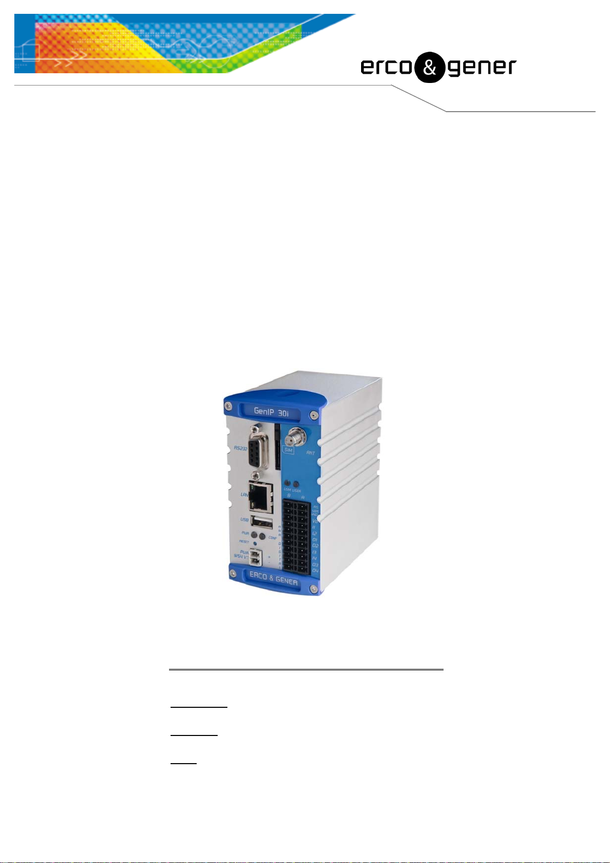
Entirely dedicated to the most critical and sensible industrial applications, the GenIP 30i with its aluminum
Din-rail casing associates the wired connections of high and very high speed (Ethernet / USB) with the
wireless world (GSM / GPRS / and 3G).
Autonomous, simple to configure (intuitive and multi-language interface) and with a high performance (ARM9
processor), it will help you all along your industrial phases concerning alarm and events management,
network interconnection (Ethernet, Modbus), command interpreter and secure storage of critical information.
For added security, the GenIP 30i is equipped with a watchdog hardware and software.
It provides a communication interface GSM / GPRS / 3G and knows how to be available and/or how to
monitor your critical equipments (Notification by email / SMS / WAN /FTP / TCP and Voice in option).
It is also able to interconnect your ASCII protocols to your new Ethernet platforms (Modbus RTU to Modbus
TCP conversion).
5 years warranty, it has the same qualities as all our products: Robustness, Reliability and Long Life.
The GenIP 30i belongs to the DIN-rail range of ERCOGENER.
This document describes the product and provides the following information:
- General presentation,
- Functional description,
- Available basic services,
- Installation and use of the GenIP 30i (first level),
- Trouble shooting,
- Recommended accessories for the use of the product.
For more information concerning this document, ERCOGENER puts at your disposal (on the Internet
www.ercogener.com or upon request) the following elements:
- Application Note
- Release Note
- Client support (Hot-Line)
Descriptions and non-contractual illustrations in this document are given as an indication only.
ERCOGENER reserves the right to make any modifications.
Dct_427_02
Page 9

EG_GenIP30i_1016_UG_004_UK Page 9 / 143
Warning
• ERCOGENER r advises to read carefully all the documents concerning the products GenIp 30i
(User Guide, Application Notes, Command List).
• ERCOGENER cannot be held responsible for:
- The problems due to an inappropriate use of the GenIP 30i.
- The problems due to a wrong configuration
- The problems due to a wrong use of an embedded software application developed and
supplied by a third party.
- The dysfunctions due to the absence or a bad coverage of the GSM, WAN networks.
- The dysfunctions if the product is used for the watching of physical persons where human
life is engaged.
• ERCOGENER reserves the right to modify the functions of its products " GenIP 30i".
- In order to avoid any risk of electrocution, do not open the casing.
- For any functioning, the casing must be closed.
- No internal part can be repaired by the user. The GenIP 30i must be returned to the factory for any repair.
- The GenIP 30i must be placed in a normally ventilated area, out of sources of heat.
- In order to guarantee the electromagnetic compatibility, the length of the USB cable and the supply cable
must not exceed 3 meters.
- The GenIP 30i must not be connected directly to the mains supply; a voltage adapter must be used.
SCRAP THE WORN BATTERIES ACCORDING TO INSTRUCTIONS.
Descriptions and non-contractual illustrations in this document are given as an indication only.
ERCOGENER reserves the right to make any modifications.
Dct_427_02
Page 10

EG_GenIP30i_1016_UG_004_UK Page 10 / 143
Copyright
The reproduction, transfer, distribution or storage of part or the totality of the contents of this document, in
any form, without the prior written authorization of ERCOGENER is strictly prohibited.
GenIP 30i is a trademark of ERCOGENER.
Hayes is a registered trademark of Hayes Microcomputer Product Inc. The names of products and
companies mentioned in this document may be names or trademarks of their respective holders.
The use of some products or services described in this document may require a paying subscription. The
availability of some products or services described in this document may change, depending on the
configurations and the materials.
In some countries, restrictions of use of the devices may be applied. For more information, thank you to
contact your nearest legally qualified local government representative.
ERCOGENER follows a method of continuous development. Consequently, ERCOGENER reserves the right
to change and improve any of its products described in this document, without notice.
The contents of this document are provided “as it is”. Except for the applicable obligatory laws, no guarantee
in any form, explicit or implicit, including but without being limited to it the implicit guarantees of aptitude to
marketing and of appropriateness to a particular use, is granted concerning the precision, the liability or the
contents of this document. ERCOGENER reserves the right to revise or withdraw this document at any time
and without notice.
In any case, ERCOGENER cannot be held responsible for any loss of data or income, as well as particular
damage, incidental, consecutive or indirect.
Descriptions and non-contractual illustrations in this document are given as an indication only.
ERCOGENER reserves the right to make any modifications.
Dct_427_02
Page 11

1 References
1.1 Referred documents
Software update Procedure:
EG_GenIP30i_1016_UP_xxx_UK
GSM reference documents:
● GSM 07.05.
● GSM 07.07.
1.2 Abbreviations
Abbreviations Definition
EG_GenIP30i_1016_UG_004_UK Page 11 / 143
AC Alternative Current
ACM Accumulated Call Meter
AT Attention (prefix for modem commands)
BTS Base Transceiver Station
CLK ClocK
CMOS Complementary Metal Oxide Semiconductor
CS Coding Scheme
CTS Clear To Send
dB Decibel
dBc Decibel relative to the Carrier power
dBi Decibel relative to an Isotropic radiator
dBm Decibel relative to one milliwatt
DC Direct Current
DCD Data Carrier Detect
DCE Data Communication Equipment as Modem...
DCS Digital Cellular System
DSR Data Set Ready
DTE Data Terminal Equipment as Computer...
DTMF Dual Tone Multi-Frequency
DTR Data Terminal Ready
EEPROM Electrically Erasable Programmable Read-Only Memory
EFR Enhanced Full Rate
E-GSM Extended GSM
EMC ElectroMagnetic Compatibility
EMI ElectroMagnetic Interference
ESD ElectroStatic Discharges
ETSI European Telecommunications Standards Institute
FIT Series of connectors (micro-FIT)
FR Full Rate
FTA Full Type Approval
GCF Global Certification Forum
GND GrouND
GPIO General Purpose Input Output
GPRS General Packet Radio Service
GSM Global System for Mobile communications
HR Half Rate
I Input
IEC International Electrotechnical Commission
IMEI International Mobile Equipment Identification
I/O
Descriptions and non-contractual illustrations in this document are given as an indication only.
Input / Output
ERCOGENER reserves the right to make any modifications.
Dct_427_02
Page 12

LED Light Emitting Diode
MAX MAXimum
ME Mobile Equipment
MIC MICrophone
Micro FIT Family of connectors from Molex
MIN MINimum
MNP Microcom Networking Protocol
MO Mobile Originated
MS Mobile Station
MT Mobile Terminated
NOM NOMinal
O Output
Pa Pascal (for speaker sound pressure measurements)
PBCCH Packet Broadcast Control Channel
PC Personal Computer
PCL Power Control Level
PDP Packet Data Protocol
PDU Protocol Description Unit
PIN Personal Identity Number
PLMN Public Land Mobile Network
PUK Personal Unblocking Key
RF Radio Frequency
RFI Radio Frequency Interference
RI Ring Indicator
RMS Root Mean Square
RTS Request To Send
RX Receive
SIM Subscriber Identification Module
SMA SubMiniature version A RF connector
SMS Short Message Service
SNR Signal-to-Noise Ratio
SPI Serial Peripheral Interface
SPL Sound Pressure Level
SPK SpeaKer
SRAM Static RAM
TCP/IP Transmission Control Protocol / Internet Protocol
TDMA Time Division Multiple Access
TU Typical Urban fading profile
TUHigh Typical Urban, High speed fading profile
TX Transmit
TYP TYPical
UTC Universal Time Clock
VSWR Voltage Stationary Wave Ratio
EG_GenIP30i_1016_UG_004_UK Page 12 / 143
Descriptions and non-contractual illustrations in this document are given as an indication only.
ERCOGENER reserves the right to make any modifications.
Dct_427_02
Page 13

EG_GenIP30i_1016_UG_004_UK Page 13 / 143
1.3 Symbols
The following symbols are used to highlight the important information of this user guide.
A symbol for the essential information concerning the module integration and performance.
A warning symbol indicates the actions that could harm or damage the module
Descriptions and non-contractual illustrations in this document are given as an indication only.
ERCOGENER reserves the right to make any modifications.
Dct_427_02
Page 14

2 Packaging
2.1 Content
The GenIp 30i is supplied with:
- a cardboard packaging,
- a GenIP 30i ,
- a straight RJ45 Ethernet cable,
- a Male/Female 9 pin cable,
- a pluggable connection female 2 pts with screw of 3.84mm,
- a pluggable connection female 22 pts with spring Push-In of 3.84mm,
- GSM hinged antenna (SMA-M),
- a technical sheet (Instructions Sheet).
EG_GenIP30i_1016_UG_004_UK Page 14 / 143
2.2 Packing case
The external dimensions of the GenIP 30i packing case are:
-.Width ............ : 163 mm,
- Height ........... : 66 mm,
- Length .......... : 295 mm.
Descriptions and non-contractual illustrations in this document are given as an indication only.
ERCOGENER reserves the right to make any modifications.
Dct_427_02
Page 15

EG_GenIP30i_1016_UG_004_UK Page 15 / 143
An identification label is put on the box side. It shows:
- The product reference (GenIP 30i),
- The CE mark,
- The serial number.
The dimensions of the label are:
- Height: 37 mm,
- Length: 70 mm.
2.3 Modem labels
Under the GenIP 30i, there is a label providing the following information:
- The ERCOGENER logo,
- The product name,
- The IP address and the subnet mask by default,
- The IMEI number with 15 digits,
- The serial number,
- The Mac address,
- The CE and RoHS Compliant marks,
- The crossed wheelie-bin mark (DEEE standards).
Descriptions and non-contractual illustrations in this document are given as an indication only.
ERCOGENER reserves the right to make any modifications.
Dct_427_02
Page 16
p
3 General presentation
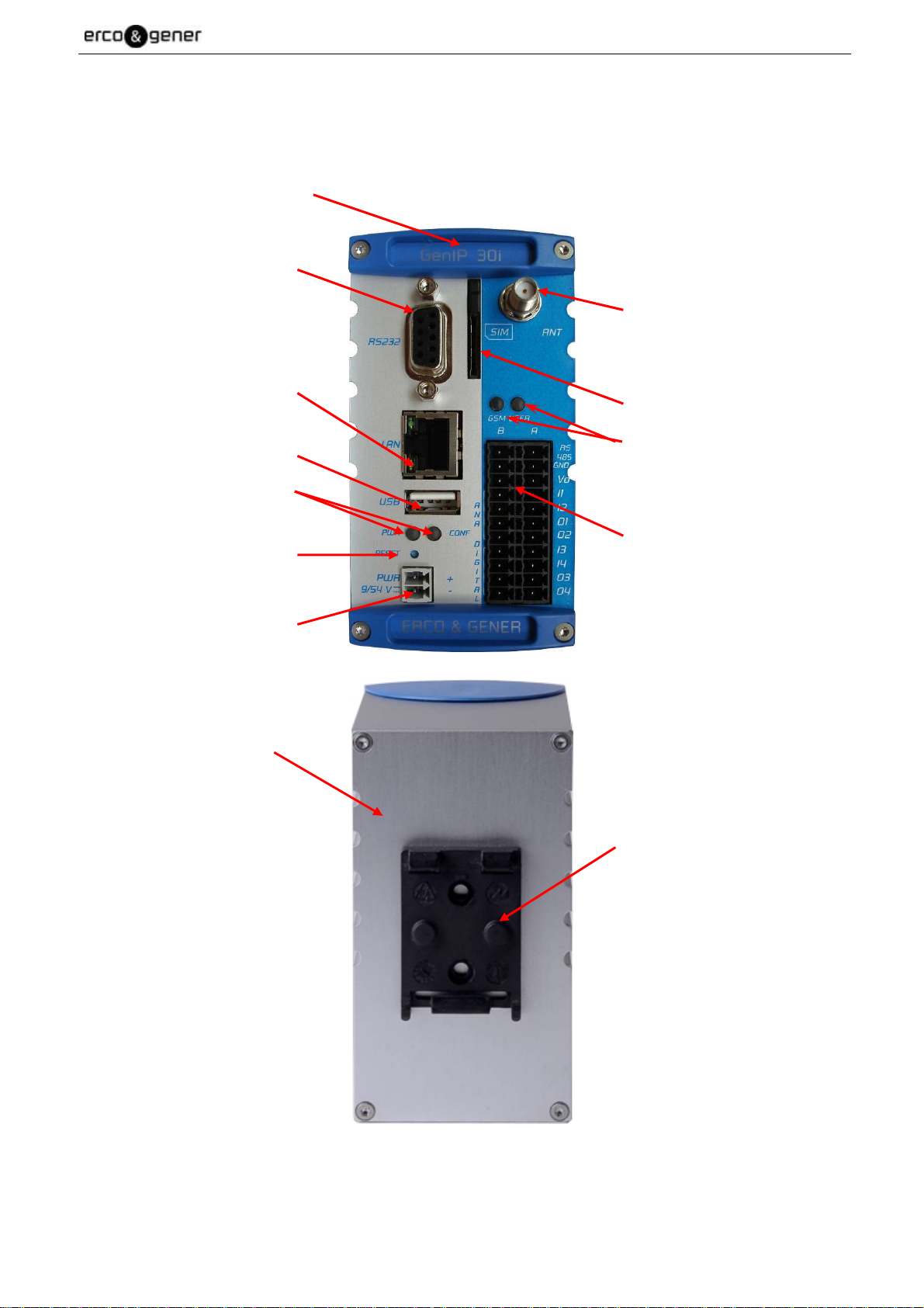
3.1 Description
Description of the GenIP 30i:
EG_GenIP30i_1016_UG_004_UK Page 16 / 143
Front side
Sub D 9pin/F connector
Ethernet and LAN Connector
USB Connector
LEDS
Reset Button
Supply Connector
SMA/F antenna connector
SIM reader
LEDS
Connector
- RS485
- V
O
- INPUT (Dig/Ana)
- OUTPUT (Dig/Ana)
- GND
Rear side
DIN-Rail fixing
Cli
Descriptions and non-contractual illustrations in this document are given as an indication only.
ERCOGENER reserves the right to make any modifications.
Dct_427_02
Page 17
EG_GenIP30i_1016_UG_004_UK Page 17 / 143
3.2 External connections
3.2.1 Connections
3.2.1.1 Antenna connector
GSM antenna connector:
The GSM antenna connector is SMA female with a 50Ω characteristic impedance.
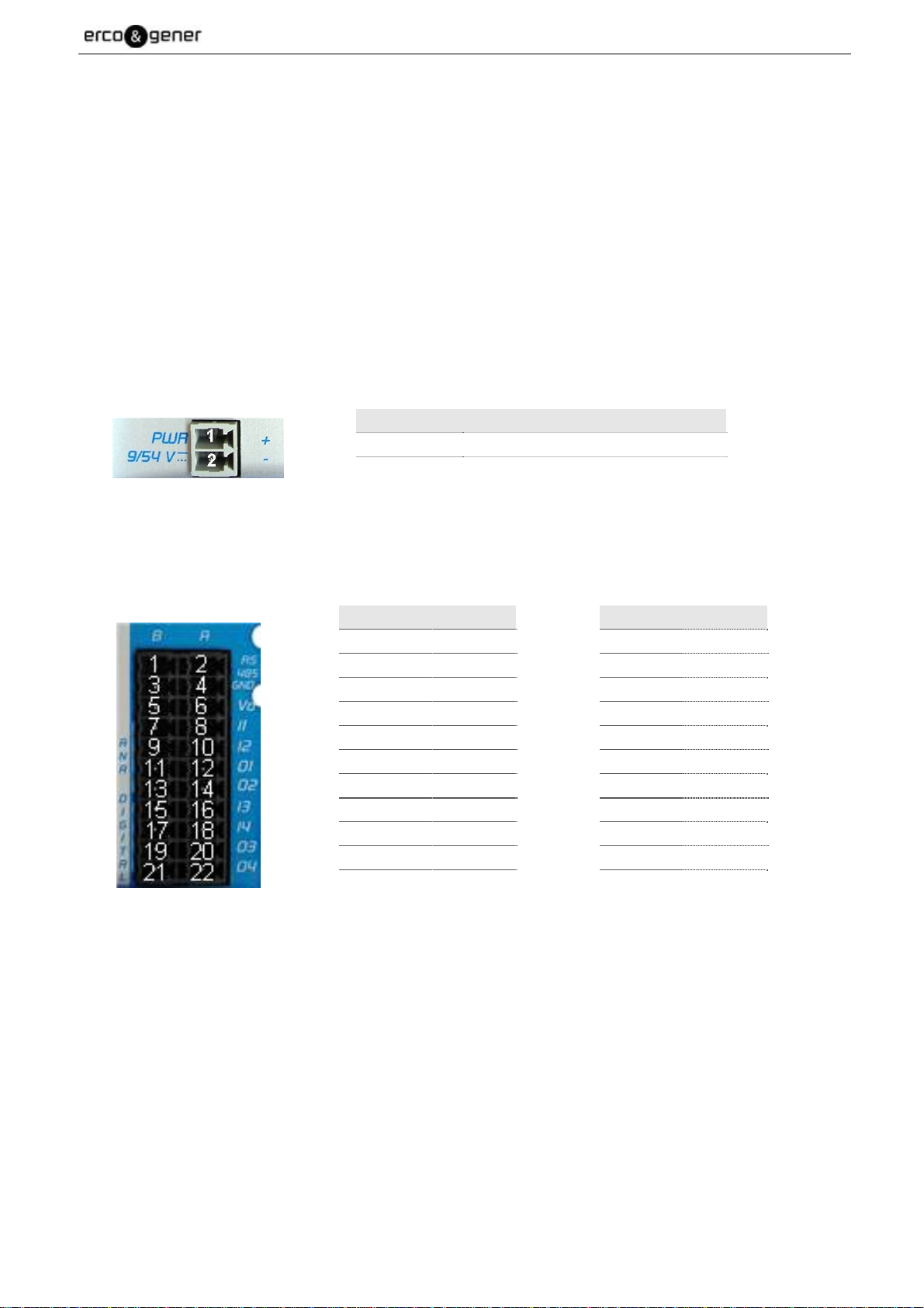
3.2.1.2 Screw connectors
Screw connectors with 2 male pins supply 9/54V
DC
:
This connector is for the power supply.
Pin N° Signal
1 + VDC
2 - GND
Pluggable connection with 22 male pins:
This connector of the GenIP 30i is a connector for the RS485, the digital and analog Inputs/Outputs.
Pin N° Signal
1 RS485 B–
3
GND
5 GND
7 GND
9 GND
11 O113 O215 GND
17 GND
19 O321 O4-
Pin N° Signal
2 RS485 A+
4 GND
6 VO
8 I1
10 I2
12 O1+
14 O2+
16 I3
18 I4
20 O3+
22 O4+
Descriptions and non-contractual illustrations in this document are given as an indication only.
ERCOGENER reserves the right to make any modifications.
Dct_427_02
Page 18
EG_GenIP30i_1016_UG_004_UK Page 18 / 143
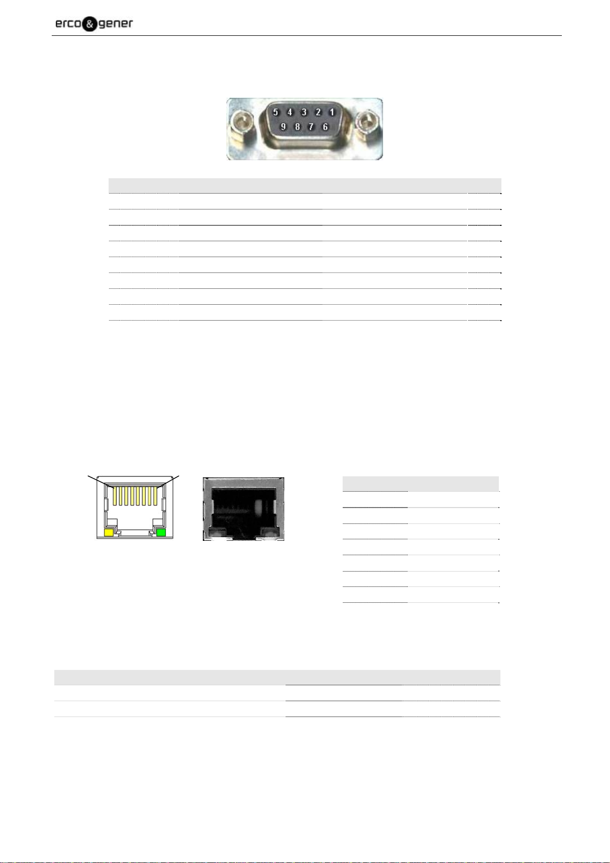
3.2.1.3 Sub D 9-pin connector
The Sub D 9-pin female connector is used for the RS232 serial link connection.
Pin N° Description Circuit (V24 – RS232C) I/O
1 Signal detection 109 – DS – DCD O
2 Data reception 104 – RD – RXD O
3 Data transmission 103 – ED – TXD I
4 Data terminal ready 108/2 – TDP – DTR I
5 Signalization ground 102 – TS – GND 6 Data set ready 107 – PDP – DSR O
7 Request to send 105 – DPE – RTS I
8 Clear to send 106 – PAE – CTS O
9 Ring indicator 125 – IA – RI O
By default, all the outgoing signals are in high level. To dialog with the GenIP 30i, only the TXD, RXD and
ground signals are essential. The other signals are not necessary.
3.2.1.4 RJ45 Ethernet LAN connector
The RJ45 connector is used for the Ethernet LAN connection. The LAN speed is 100 Mbits.
1 8
Pin N° Signal
1 TD+
2 TD3 RD+
4 CT
5 CT
GenIP 30i accepts straight or crossed Ethernet cables.
6 RD7 NC
8 GND
Status of the connector leds
Action LED Status
At powering ON Green and yellow OFF
When LAN is electrically connected Yellow Fixed
Exchanges of information on LAN Green Flashing
Descriptions and non-contractual illustrations in this document are given as an indication only.
ERCOGENER reserves the right to make any modifications.
Dct_427_02
Page 19

3.2.1.5 USB connectors
The GenIP 30i provides 2 connectors.
EG_GenIP30i_1016_UG_004_UK Page 19 / 143
Pin name Signal
1 Power +5V (V
BUS
2 Data (D-)
3 Data (D+)
4 Ground (GND)
3.2.1.6 Reset Button
The "Reset" button is situated under the 2 LEDS "PWR" and "CONF".
It can be pressed thanks to an accessory of a diameter < 2mm (paperclip for example)
This button has two functions:
• Reloading the factory configuration,
• Reloading the reference configuration.
) 500mA max.
Procedure for reloading the factory configuration:
• Turn the GenIP 30i OFF,
• Press the Reset button,
• Turn the GenIP 30i ON,
• Wait 30 seconds before the CONF led flashes and the GSM led turns ON or flashes.
• Release the Reset button,
• Wait PWR fixed and after blinked
• From now on, the factory parameters are reloaded.
Procedure for reloading the reference configuration:
To work, there must have been a reference configuration saved in the GenIP 30i.
If there was no reference configuration saved, then the factory configuration will be loaded.
• The GenIP must be powered ON and the Power led must be flashing,
• Press during 5 seconds the Reset button,
• After a few seconds, the led Power is fixed.
• Release the button
• Then the Power led flashes, indicating that the procedure is now finished,
• From now on, the GenIP 30i has reloaded the reference configuration parameters (IP address,
mask...).
Descriptions and non-contractual illustrations in this document are given as an indication only.
ERCOGENER reserves the right to make any modifications.
Dct_427_02
Page 20

EG_GenIP30i_1016_UG_004_UK Page 20 / 143
3.2.2 Accessories supplied
3.2.2.1 Straight cable 9pin M/F
The straight cable 9pin M/F allows to dialog via the RS232.
Component Characteristics
Straight cables 9pin Male/Female Length ≈ 2m
9 wires
Lockings
Pin N° Designation Circuit (V24 – RS232C)
1 Signal detection 109 – DS – DCD
2 Data reception 104 – RD – RXD
3 Data transmission 103 – ED – TXD
4 Data terminal ready 108/2 – TDP – DTR
5 Signalization ground 102 – TS – GND
6 Data set ready 107 – PDP – DSR
7 Request to send 105 – DPE – RTS
8 Clear to send 106 – PAE – CTS
9 Call indicator 125 – IA – RI
Descriptions and non-contractual illustrations in this document are given as an indication only.
ERCOGENER reserves the right to make any modifications.
Dct_427_02
Page 21

EG_GenIP30i_1016_UG_004_UK Page 21 / 143
3.2.2.2 Ethernet RJ45 straight cable
The RJ45 Ethernet cable allows to dialog via the LAN Ethernet.
Component Characteristics
RJ45 straight Ethernet cables Length ≈ 2m
8 wires
RJ45+S/R (YUS-01)
3.2.2.3 GSM hinged antenna (SMA-M)
A GSM hinged antenna (SMA Male connection) is supplied with the GenIP 30i.
It is possible and advised to use an antenna with cable for swerving needs.
Component Characteristics
GSM hinged antenna
Dimension straight : 90 mm
Dimension bent at 90°C : 30 x 70 mm
SMA-M GSM 850 / 900 / 1800 / 1900 / 3G
Descriptions and non-contractual illustrations in this document are given as an indication only.
ERCOGENER reserves the right to make any modifications.
Dct_427_02
Page 22

EG_GenIP30i_1016_UG_004_UK Page 22 / 143
4 Technical characteristics and Options
The GenIP 30i is a gateway Ethernet, RS232, RS485 to GSM / GPRS / 3G.
4.1 Technical characteristics
The GSM/GPRS/3G characteristics and the functions are summarized in the table hereunder.
GSM/GPRS/3G characteristics
- E-GSM 850 MHz
900 MHz
1800 MHz
3G 2100 MHz
- ETSI GSM Phase 2+ Class 4 (2W)
Class 1 (1W)
- EGPRS Class 10 (Up to 4Rx / 2Tx)
- HSDPA features – 3GPP Release 5
- UMTS features - 3GPP Release 4
Functions
Secured parameters interface (HTTPS / Login / Password)
Multi-language parameters interface (FR / UK)
Multi-Language hotline (FR / UK)
Embedded Web server: APACHE
Parameters interface accessible via the Ethernet and GSM / GPRS link
Back-up of a configuration in a text file
Port Forwarding
Firewall integrated with automatic management
Alarms management : Transmission of email / SMS / GSM frame / GPRS frame
Converter ModBus TCP / ModBus RTU
Information storage
Routing IP (RIP)
Linux IP Stack: TCP / UDP / FTP,
DHCP client and server,
SMTP / POP3 (Via Ethernet and/or GPRS),
HTTPS / HTTP
Client : DYNDNS / SNTP
VPN SSL or VPN IPSec
Client : GnuDIP
GPRS connection automatic, systematic or upon events
Complete set of Macro Commands
Diagnostic and administration tools integrated
Events diary
Watch Dog hard and soft
Interfaces
RS232 : Sub-D 9-M
RS485 : Connector
USB (Host)
RJ45 Ethernet Port (10 / 100 Mbps)
Antenna connector SMA-F
Descriptions and non-contractual illustrations in this document are given as an indication only.
ERCOGENER reserves the right to make any modifications.
Dct_427_02
Page 23

EG_GenIP30i_1016_UG_004_UK Page 23 / 143
Large band supply : 9 to 54 Vdc
SIM reader with holder (3V – 1.8V)
4 Leds : PWR / CONF / GSM / USER (configurable)
4.2 Accessories and Options
The Accessories and Options are described in the table hereunder.
Accessories
Screw connection (Power supply, RS485)
Spring connections Push-In (RS485, VO, I/O)
RS232 cable (Sub-D 9-M / Sub-D 9-F)
Straight Ethernet cable
GSM hinged antenna (SMA-M)
Options (*)
High output GSM / GPRS/3G antenna
USB cable
Standard mains block
Tropicalization
(*) Options, contact us.
4.3 Backup battery
The GenIP 30i is equipped with a battery which maintains the real-time clock.
This battery has a 20-week autonomy, with the equipment OFF.
The charging time is 4 days.
When it is discharged, it does not affect the good working of the equipment. Only a clock updating will be
necessary when powering ON the GenIP 30i.
4.3.1 Characteristics of the battery
Technology
Nominal Voltage
Capacity
Dimensions
Ni-Mh (Nickel - Metal hydride)
1.2 V
40 mAh
Ø 11.5 x 5.35 mm
SCRAP THE WORN BATTERIES ACCORDING TO INSTRUCTIONS
Descriptions and non-contractual illustrations in this document are given as an indication only.
ERCOGENER reserves the right to make any modifications.
Dct_427_02
Page 24
EG_GenIP30i_1016_UG_004_UK Page 24 / 143
5 Using the GenIP 30i
5.1 Starting with the GenIP 30i
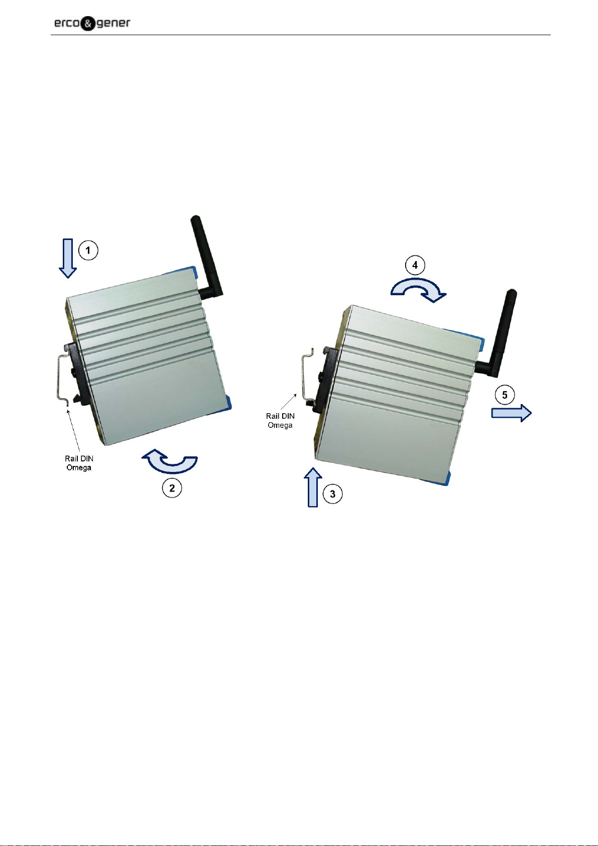
5.1.1 Assembling and disassembling the GenIP 30i
By default, the modem is provided with a Din-Rail fixing clip (35mm) directly assembled on the modem.
The Din-Rail fixing clip (35mm) allows a quick assembling/disassembling on a DIN-Rail (35mm) OMEGA
(IEC/EN 60715 / DIN (35mm) 7.5mm).
To mount the modem on a DIN-Rail (35mm), follow the step 1 (pressure) and the step 2 (turn).
To remove the modem from the DIN-Rail (35mm), follow the step 3 (pressure) and the steps 4-5 (turn and
remove).
Descriptions and non-contractual illustrations in this document are given as an indication only.
ERCOGENER reserves the right to make any modifications.
Dct_427_02
Page 25
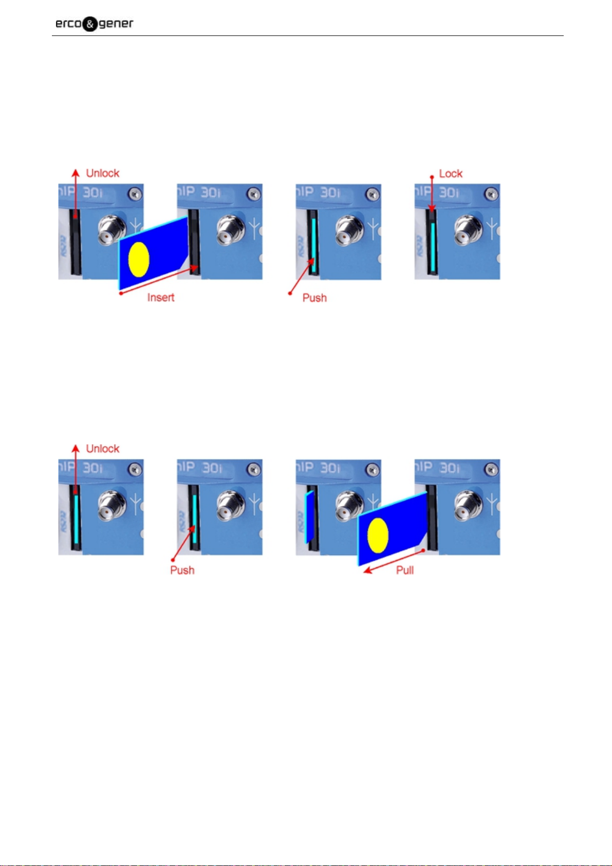
5.1.2 SIM card Access
5.1.2.1 Insertion Carte SIM
- Unlock
- Carefully insert the SIM card in the SIM card reader.
- Push the SIM card until hearing a "clic" which ensures its correct positioning.
- Lock
EG_GenIP30i_1016_UG_004_UK Page 25 / 143
5.1.2.2 SIM card Removal
- Unlock
- Push the SIM card until hearing a "clic" which ensures its removal.
- Carefully remove the SIM card from the SIM card reader.
- Lock
Descriptions and non-contractual illustrations in this document are given as an indication only.
ERCOGENER reserves the right to make any modifications.
Dct_427_02
Page 26

EG_GenIP30i_1016_UG_004_UK Page 26 / 143
5.1.3 Installation of the GenIP 30i
To install the GenIP 30i, it is recommended to do the following operations with the modem turned off:
- Insert the SIM card in the drawer respecting the direction, and carefully insert them in the reader.
- Check that the SIM card is correctly positioned.
- Screw the GSM hinged antenna in the SMA connector.
- For the connection to the DTE, connect the LAN link via the straight Ethernet RJ45 cable.
- Screw the supply cable in the 2-pin connector, respecting the polarities, and connect to the
external power DC supply source, stabilized and regulated.
- Connect the 2-pin connector with the supply cable in the GenIP 30i and turn the external supply
source on (the LED PWR must turn on).
-
When the "PWR" led flash, The GenIP 30i is ready.
To set the parameters of the different functions of the GenIP 30i, the use of an internet browser is advised.
Descriptions and non-contractual illustrations in this document are given as an indication only.
ERCOGENER reserves the right to make any modifications.
Dct_427_02
Page 27
EG_GenIP30i_1016_UG_004_UK Page 27 / 143
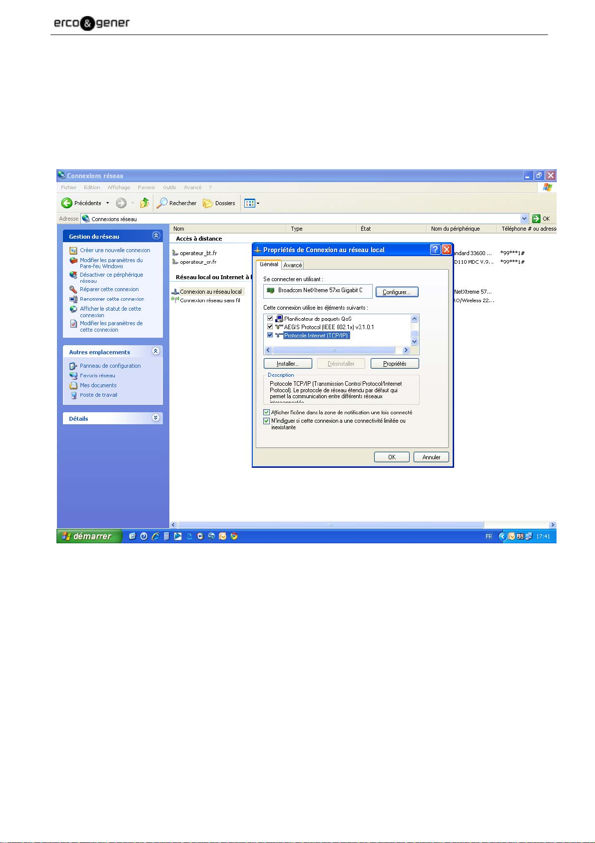
5.1.4 Using the GenIP 30i with the browser
To use and configure the GenIP 30i, the IP address and the subnet mask must be entered.
This window is in the Control Panel / Internet and Network Connections / Connection to local network /
Internet Protocol (TCP/IP) / Properties
Example under XP.
Descriptions and non-contractual illustrations in this document are given as an indication only.
ERCOGENER reserves the right to make any modifications.
Dct_427_02
Page 28
EG_GenIP30i_1016_UG_004_UK Page 28 / 143
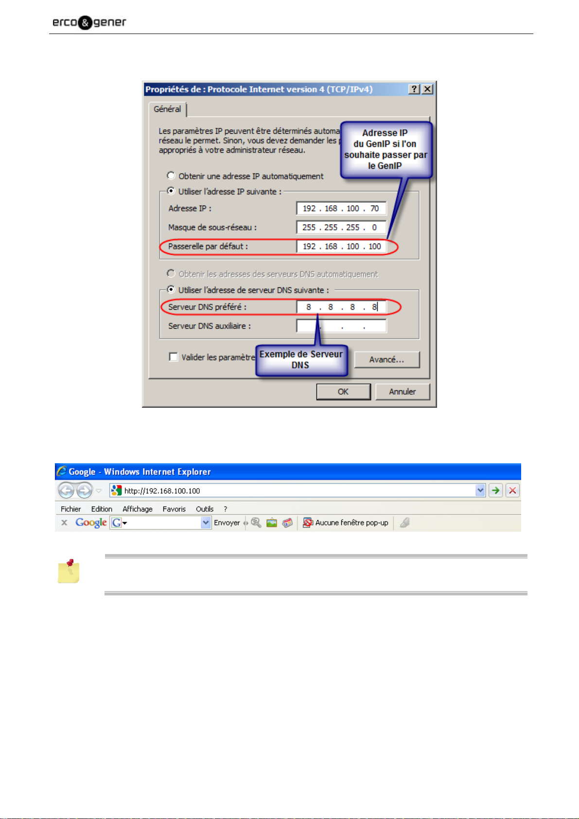
In the window Internet Protocol Properties (TCP/IP), enter an IP Address and the subnet mask (see
hereunder) and validate with OK
Use a browser (Internet Explorer for example) and enter the IP address by default of the GenIP 30i.
Just one access is possible to IHM.
Descriptions and non-contractual illustrations in this document are given as an indication only.
ERCOGENER reserves the right to make any modifications.
Dct_427_02
Page 29

EG_GenIP30i_1016_UG_004_UK Page 29 / 143
To authenticate, enter the user name (admin) and the password (admin) and validate.
To be able to validate a WAN connection, in the section “My communications / Modem” enter the parameters
of the access supplier.
To be taken into account it has to be validated.
The GenIP 30i will warn you that it has to be restarted so that the new parameters can be taken
into account.
Once the GenIP 30i has restarted, it is advised to make a WAN connection and to send a SMS
to validate the GSM and WAN connectivity.
Descriptions and non-contractual illustrations in this document are given as an indication only.
ERCOGENER reserves the right to make any modifications.
Dct_427_02
Page 30
EG_GenIP30i_1016_UG_004_UK Page 30 / 143
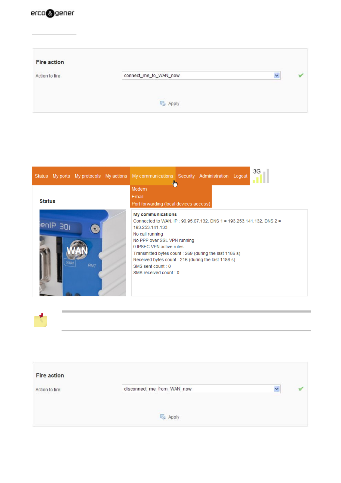
WAN Connection
In the section “My actions / Action Management / Actions List”, validate connect_me_to_WAN_now.
The page refreshes, then click on the section “Status” and place the mouse on the section “My
Communications”.
Once connected to the WAN network, a dynamic IP address is given (for example hereunder: 90.94.237.5).
Click "Status" and drag "My communications"
The WAN connection can take a few seconds
To disconnect, in the section “My actions” you must execute the action disconnect_me_from_WAN_now.
Descriptions and non-contractual illustrations in this document are given as an indication only.
ERCOGENER reserves the right to make any modifications.
Dct_427_02
Page 31

EG_GenIP30i_1016_UG_004_UK Page 31 / 143
Sending a SMS
In the section “My actions / Action Management / Actions List”, click on SMS_a_test_SMS.
In the window “Add or Edit an Action”, enter the telephone number of the addressee and validate
In the section “My actions / Actions Setting / Action to fire”, validate SMS_test.
After a few seconds depending on the operator, the addressee will receive the following message: test.
Descriptions and non-contractual illustrations in this document are given as an indication only.
ERCOGENER reserves the right to make any modifications.
Dct_427_02
Page 32

EG_GenIP30i_1016_UG_004_UK Page 32 / 143
5.2 Basic principle
The GenIP 30i is a device which can follow on with actions upon internal or external events.
These events can come from or be initiated:
• by the interfaces : Ethernet, RS232 or RS485,
• by the logic, analog input,
• temporally,
• at powering on the GenIP 30i,
• from a distance via SMS, GPRS,3G, GSM Data or GSM PPP.
The actions may be chained and acknowledged.
In case of chaining, the actions must be compatible between each other. For example, if you are in WAN
connection, you won’t be able to receive at the same time a GSM Data communication.
As well, if you use a data or DTMF connection, the SMS and email reading cannot be done.
5.2.1 Actions
In the GenIP 30i, on the menu My actions and Actions management, you will find some predefined actions
and you can add your actions.
An action is what the GenIP 30i will do after an event.
Once an action is realized, we can decide to wait for an acknowledgement.
For example sending a SMS and waiting for an acknowledgement.
5.2.1.1 Definition of course of actions in a script
The use of an action in a script allows to start this action and go to the next instruction even if this action is
not finished. This is not the case with a macro which will wait for the action to be finished before going to the
next instruction of the script.
Example
: Sending SMS using a script in case of network problems
The action Envoi_Sms is created. This sent to +33111111111 the sms Test SMS
Using this action Envoi_Sms in a script tries to send the SMS and then go to the next instruction. If network
problems persist, the SMS will be sent as soon as the network is operational without it disrupting the script.
In the case of the use the macro send sms +3311111111 Test SMS the GenIP reiterate the sending of SMS
until the network again become operational, but will not go to the next instruction until the SMS is not send.
Descriptions and non-contractual illustrations in this document are given as an indication only.
ERCOGENER reserves the right to make any modifications.
Dct_427_02
Page 33

EG_GenIP30i_1016_UG_004_UK Page 33 / 143
5.2.1.2 Pilot an action in DTMF
It is possible to activate an action by a DTMF command with the following syntax:
*Action number* Example : *3*
The ' Action number ' is the number that appears in the list of actions of the web interface.
By default, this feature is not active.
The activation is done through the next hidden page.
http://vvv.xxx.yyy.zzz/actions_management_advanced.php
Choose "Run an action" then "Apply"
In the same communication, it is not possible to send and acknowledge an action.
For this it is necessary to establish two communications.
Descriptions and non-contractual illustrations in this document are given as an indication only.
ERCOGENER reserves the right to make any modifications.
Dct_427_02
Page 34

EG_GenIP30i_1016_UG_004_UK Page 34 / 143
5.2.2 Events
An event can be characterized by a local frame coming from the ports, an incoming SMS, an incoming email
or a temporal logic or analog input triggering.
These events can be associated to one or several actions.
Example: On a TCP or RS port, we can watch a frame like ALARM
If it appears, we decide to send a SMS to one or several numbers
5.2.2.1 Planning events
Events can be scheduled periodically or by date.
To access the program click on "Administration" and then drag the mouse on "Time"
Descriptions and non-contractual illustrations in this document are given as an indication only.
ERCOGENER reserves the right to make any modifications.
Dct_427_02
Page 35

EG_GenIP30i_1016_UG_004_UK Page 35 / 143
Some actions can be planned. To reduce the consumption of CPU resource, checking this
acknowledgment is done by default every 60 seconds
It is possible to change this frequency through the next hidden page.
http://vvv.xxx.yyy.zzz/actions_management_advanced.php
You choose the right compromise.
Descriptions and non-contractual illustrations in this document are given as an indication only.
ERCOGENER reserves the right to make any modifications.
Dct_427_02
Page 36

EG_GenIP30i_1016_UG_004_UK Page 36 / 143
5.2.3 Pattern
A pattern can be a character or frame character AXCII or Hexa
For example, if we receive the following information on the RS232:
ABCD123456789AZERTY
You can search :
Character : D
Frame character : D123
5.2.3.1 Management of characters in the buffer
When viewing the contents of the buffer, some characters in the ASCII table are substituted. (See table
below).
Ex : the carriage return (0x0D) is display \r.
Table of characters substituted
Decimal Hexadecimal ASCII Substitution display
9 0x09 TAB \t
10 0x0A Line Feed \n
13 0x0D Carriage Return \r
32
:
126
0x20
:
0x7E
All other characters in the ASCII table are displayed in hexadecimal form \x00.
Ex : le character Back Space is display \x08
Ex : le character CtrlZ is display \x1A
The character \ (anti Slash) is doubled. It is displayed \ \.
Ex : the string sent \test\ It is displayed \\test\\
Space
~
No think.
All characters are displayed
as such.
Descriptions and non-contractual illustrations in this document are given as an indication only.
ERCOGENER reserves the right to make any modifications.
Dct_427_02
Page 37

EG_GenIP30i_1016_UG_004_UK Page 37 / 143
5.2.4 Acknowledgements
The acknowledgements are digital (Between 1 and 65535) and can be done by:
• WAN via email, TCP connection on Service Port (by default : 1224) or via Web Interface,
• LAN via TCP connection on Service Port (by default: 1224) or directly in the Web interface,
• SMS
• GSM Data PPP in TCP connection on Service Port (by default: 1224) or via Web Interface,
• GSM Data directed to service Socket (by default: 1224).
• DTMF upon voice incoming call. It is possible to perform an action for the issuance of a voice
message.
A non-acknowledgement of an action is not considered as a failure of this action. An action is
considered as a failure if it could not be done. For example, impossible to send an email or to
connect in data mode.
5.2.4.1 Acknowledgement via Macro Command
For the acknowledgements syntax, see the table of Macro Commands (paragraph 5.2.6 Macro Commands).
Example of acknowledgements:
The GenIP 30i is protected by a password adminremote and we want to acquitter the alarm code 1.
Through a command port, you will have to send the following information:
password adminremote;
ack 1;
end;
Do not forget the semi colon after each command and the end which marks the end of the
actions to do.
• For the emails, you will have to activate a periodic reading of email or to validate the reading
before deadline.
• The acknowledgements can come from different services or access authorized. For
example sending a SMS with acknowledgement does not require an acknowledgement by
SMS.
• Do not forget to activate the authorized sources; otherwise you won’t be able to
acknowledge the actions.
• Acknowledgements by e-mail :
Considering that the size and the content of the e-mail received are voluntarily limited to
minimize consumption, you must:
Work in text (Necessary, otherwise email refused).
Remove from your e-mail the business cards, signatures or other elements which
unnecessarily take a lot of place and generate additional consumption of data when
connecting in WAN.
Descriptions and non-contractual illustrations in this document are given as an indication only.
ERCOGENER reserves the right to make any modifications.
Dct_427_02
Page 38

EG_GenIP30i_1016_UG_004_UK Page 38 / 143
5.2.4.2 Acknowledgement via DTMF
With a telephone, call the GenIP 30i on the voice number.
On receipt of the call, the GenIP 30i answers and sends series of vocal frequencies.
After that, you can acknowledge an alarm with the following syntax:
# Alarm number# Example: #3#
If the syntax is correct you will receive a short beep, if it is incorrect a long beep.
Then you can hang-up your telephone.
It is possible to acquit an action during a voice message.
It is possible to acknowledged all actions pending acknowledge by the '*' character.
To do this, open hidden next page.
http://vvv.xxx.yyy.zzz/actions_management_advanced.php
Choose "Acknowledge all" then "Apply"
Then receipt the DTMF character '*' all actions will be acknowledge.
Descriptions and non-contractual illustrations in this document are given as an indication only.
ERCOGENER reserves the right to make any modifications.
Dct_427_02
Page 39

EG_GenIP30i_1016_UG_004_UK Page 39 / 143
5.2.5 Remarks about syntax of acknowledgements, Macro Commands, patterns or frames received upon action starting
Some of them are sensitive to the case (Respect of small letters and CAPITAL LETTERS).
In certain fields of the Web interface, the following characters are not accepted:
• Character like –
• Stressed character
• White character
When a character is not valid, a red cross in the Web interface or an error message in the case
of acknowledgement or Macro Commands appear.
5.2.5.1 Reaction of the GenIP 30i in case of authorized sources and syntax error
In relation to the command channels and the Macro Commands syntax, the reaction of the GenIP 30i will be:
Action Result
If number, IP address or email not authorized on the
GenIP 30i side
The SMS is not read
The TCP connection is denied
The email is not read
The Macro Command is read and the GenIP 30i
does not reply.
If number, IP address or email authorized and Macro
Command with syntax error
After 3 attempts, the number, IP address or email is
Black Listed.
To take it out from the Black List, you have to send
again a correct syntax or make a Reboot of the
GenIP 30i
Frames and fields quantification
Designation
Size Maxi accepted for e-mail file The e-mail file must not exceed 35 Kilos.
Size Maxi accepted for e-mail content
Size Maxi of the frame to program the dynamic
messages
The content (text, signs, business cards ...) must not
exceed 1024 bytes.
1024 bytes
Size Maxi for fields in the Web interface 1024 bytes
Size Maxi possible for diary
Number of declarable users for the access to the
Web interface
4,5 Mega bytes. (Careful, if you reach this size, the
display of the page will take a long time)
10 users
Descriptions and non-contractual illustrations in this document are given as an indication only.
ERCOGENER reserves the right to make any modifications.
Dct_427_02
Page 40

EG_GenIP30i_1016_UG_004_UK Page 40 / 143
5.2.6 Macro Commands
A macro command corresponds to a command syntax allowing to do an action.
For example, the Macro command connect_me_to_WAN_now tells the GenIP 30i to connect to WANnetwork
(GPRS or 3G) and to send back the WAN IP address obtained to the initiator of this Macro command. If you
send this Macro Command to the GenIP 30i via SMS, then you will receive the WAN IP address via SMS.
As well as for the acknowledgements, you have to be registered on the authorized sources.
(See the Table Macro command hereunder).
The Macro commands may come from:
• WAN via e-mail, TCP connection on Service Port (by default : 1224) or via Web Interface,
• LAN via TCP connection on Service Port (by default: 1224) or directly in the Web Interface,
• SMS
• GSM Data PPP in TCP connection on Service Port (by default: 1224) or via Web Interface,
• GSM Data directed to service Socket (by default: 1224).
Example of Macro Commands:
The GenIP 30i is protected by a password adminremote and we want to read the GenIP 30i version.
Through a command port, you will have to send the following information:
password adminremote;version;end;
Do not forget the semi colon after each command and the “end;” which marks the end of the
Macro commands to do.
On the Web interface of the GenIP 30i, you will find a Macro command builder which will help you to enter
these Macro commands.
Macro ack
Format
Description
Remarks about
Macro commands
Example
Message sent after
execution of the
action
ack {code}
Acknowledges the acknowledgement waiting time for the code 1
Different possibilities:
ack x-y acknowledges the actions whose codes are between x and y included.
ack name acknowledges the action by its name (Characters * and ? as joker).
ack 1;end;
ack 1
OK
Descriptions and non-contractual illustrations in this document are given as an indication only.
ERCOGENER reserves the right to make any modifications.
Dct_427_02
Page 41

EG_GenIP30i_1016_UG_004_UK Page 41 / 143
Macro define apn From software release > V450
Format
Description
Remarks sur les
Macro commands
Example
Remarks sur les
Macro commands
define apn
Define temporarily the apn.
Useful if you forget to set apn into the Gen IP
define apn name apn;end;
define apn name apn
OK
Macro delete all gv From software release > V450
Format
Description
Remarques sur les
Macro commandes
Exemple
Remarques sur les
Macro commandes
delete all gv
Delete all global variables.
Useful for the development of scripts
delete all gv;end;
delete all gv
OK
Macro do action
Format
Description
Remarks about
Macro commands
Example
Message sent after
execution of the
action
do action {name of the action}
Sends the content of the message 0 (with the example above TEST)
do action nom_action;end;
do action
name_action
OK
Macro echo
Format
Description
Remarks about
Macro commands
Example 1
Message sent after
execution of the
action 1
Example 2
Message sent after
execution of the
action 2
echo
Return text that follows the command
Return the value of the variable LAN_IP
echo LAN_IP;end;
LAN_IP
OK
echo $LAN_IP$;end;
192.168.100.100
OK
Descriptions and non-contractual illustrations in this document are given as an indication only.
ERCOGENER reserves the right to make any modifications.
Dct_427_02
Page 42

EG_GenIP30i_1016_UG_004_UK Page 42 / 143
Macro email receive
Format
Description
Remarks about
Macro commands
Example
Message sent after
execution of the
action
email receive
Triggers the reading of e-mails
Via the Data link, the action will be done after hanging-up the Data communication
and in this case, no message is sent back.
email receive;end;
email receive
OK
Macro emergency reboot
Format
Description
Remarks about
Macro commands
Example
emergency reboot
Emergency Reboot, no response
Works only via SMS
emergency reboot;end
Message sent after
execution of the
action
Macro end
Format
Description
Remarks about
Macro commands
Example
end
Signals the end of macro commands series to avoid problems of advertisings,
signatures...
Instruction necessary after each Macro command or after Macro commands frame.
See here after the example
end
Message sent after
execution of the
None
action
Macro ftp get binary
Format
Description
Remarks about
Macro commands
Example
ftp get binary {ftp server port} {file path} {account} {password} {hex binary content}
Receive binary from file FTP server.
File < 20 Ko
ftp get binary linux.fr.oleane.com 21 FCO/fabien.txt myusername mypassword;end;
ftp get binary linux.fr.oleane.com 21 FCO/fabien.txt myusername mypassword
Message sent after
execution of the
action
9 bytes
010203040506070809
OK
Descriptions and non-contractual illustrations in this document are given as an indication only.
ERCOGENER reserves the right to make any modifications.
Dct_427_02
Page 43

EG_GenIP30i_1016_UG_004_UK Page 43 / 143
Macro ftp get file From software release > V408
Format
Description
Remarks about
Macro commands
Ftpget file {ftp server port} {file path} {account} {password} {unsaved_user_file_name}
Receive a file using FTP and store it into the GenIP
Maximum storage 100 méga bytes in RAM
Maximum storage 1 méga bytes in NVRAM.
Receive a file using FTP and send it by mail:
Example
ftp get file 192.168.100.175 21 /configuration.zip Loging PassWord
unsaved_user_file_test;end;
send email xxx@yyy.zz file://unsaved_user_file_test;end;
tp get file 192.168.100.175 21 /configuration.zip Loging PassWord
Message sent after
execution of the
action
unsaved_user_file_test
13133 bytes got
OK
send email xxx@yyy.zz file://unsaved_user_file_test
OK
Macro ftp get text
Format
Description
Remarks about
Macro commands
Example
Message sent after
execution of the
action
ftp get text {ftp server address} {ftp server port} {file path} {account} {password}
Receive text from file server FTP
File < 20 Ko
ftp get text linux.fr.oleane.com 21 FCO/fabien.txt myusername mypassword;end;
ftp get text linux.fr.oleane.com 21 FCO/fabien.txt myusername mypassword
12 Bytes
test message
OK
Macro ftp put binary
Format
Description
Remarks about
Macro commands
Example
Message sent after
execution of the
action
ftp put binary {ftp server address} {ftp server port} {file path} {account} {password}
{hex binary content}
Send binary file to server FTP
File < 20 Ko
ftp put binary linux.fr.oleane.com 21 FCO/fabien.txt myusername mypassword
AA5A2F8e11;end;
ftp put binary linux.fr.oleane.com 21 FCO/fabien.txt myusername mypassword
AA5A2F8e11
OK
Macro ftp put file From software release > V408
Format
Description
Remarks about
Macro commands
Example
Message sent after
execution of the
action
ftp put file{ftp server port} {file path} {account} {password} {unsaved_user_file_nom de
fichier}
Post file from internal GenIP to FTP server
Maximum storage 100 méga bytes in RAM
Maximum storage 1 méga bytes in NVRAM.
ftp put file 192.168.100.175 21 /Fichier.zip Identifiant MotDePasse
unsaved_user_file_test;end;
ftp put file 192.168.100.175 21 / Fichier.zip Identifiant MotDePasse
unsaved_user_file_test
13133 bytes put
OK
Descriptions and non-contractual illustrations in this document are given as an indication only.
ERCOGENER reserves the right to make any modifications.
Dct_427_02
Page 44

EG_GenIP30i_1016_UG_004_UK Page 44 / 143
Macro ftp put text
Format
Description
Remarks about
Macro commands
Example
Message sent after
execution of the
action
ftp put text {ftp server address} {ftp server port} {file path} {account} {password} {text
content}
Send text to server FTP
File < 20 Ko
ftp put text linux.fr.oleane.com 21 FCO/fabien.txt myusername mypassword test
message;end;
ftp put text linux.fr.oleane.com 21 FCO/fabien.txt myusername mypassword test
message
OK
Macro get custom
Format
Description
Remarks about
Macro commands
Example
Message sent after
execution of the
action
get custom {index}
Sends the content of the message 0 (with the example above TEST)
get custom 0;end;
get custom 0
TEST
OK
Macro get lan ip
Format
Description
Remarks about
Macro commands
Example
get lan ip
Provides the IP address LAN
get lan ip;end;
Message sent after
execution of the
get lan ip y.y.y.y
action
Macro get wan ip
Format
Description
Remarks about
Macro commands
Example
Message sent after
execution of the
action
Descriptions and non-contractual illustrations in this document are given as an indication only.
get wan ip
Provides the IP address on WAN side
get wan ip;end;
get wan ip WAN IP = x.x.x.x
ERCOGENER reserves the right to make any modifications.
Dct_427_02
Page 45

EG_GenIP30i_1016_UG_004_UK Page 45 / 143
Macro last_macro_command_result
Format
Description
Remarques sur les
Macro commandes
Exemple 1
last_macro_command_result
Save the result of the last order.
last_macro_command_result return 1 for OK or 0 for ERROR
If you use this command, it is interesting to use the command no all for not have a
duplicate reporting
version;echo $last_macro_command_result$;end;
Version
Message renvoyé
après l'exécution
de l'action
000464
OK
echo 1
1
OK
Exemple 2
Message renvoyé
après l'exécution
de l'action
no all;version;echo $last_macro_command_result$;end;
000464
1
Macro last_macro_command_result_string
Format
Description
Remarques sur les
Macro commandes
Exemple 1
last_macro_command_result_string
Save the result of the last order.
last_macro_command_result_string return OK or ERROR
If you use this command, it is interesting to use the command no all for not have a
duplicate reporting.
version;echo $last_macro_command_result_string$;end;
Version
Message renvoyé
après l'exécution
de l'action
000464
OK
echo OK
OK
OK
Exemple 2
Message renvoyé
après l'exécution
de l'action
no all;version;echo $last_macro_command_result_string$;end;
000464
OK
Macro modbus write
Format
modbus write {@} {code} {reg} {nb} {type} {val}
Write the value val into register reg at the peripheral 'address @.
@ peripheral 'address.
code write function (5, 6, 15 ou 16)
Description
reg register address in decimal
nb number of register to write (register de 16 bits)
type type of the write value (int, uint, hex, bit …)
val write value
Remarques sur les
Macro commandes
Exemple
Message renvoyé
après l'exécution
de l'action
See § 5.3.5.5, 5.3.5.6, 5.3.5.7 and 5.3.5.8
modbus write 1 5 0 1 bit 0;end; Close the logic output 1 of the GenIp.
modbus write 1 5 0 1 bit 0
OK
Descriptions and non-contractual illustrations in this document are given as an indication only.
ERCOGENER reserves the right to make any modifications.
Dct_427_02
Page 46

EG_GenIP30i_1016_UG_004_UK Page 46 / 143
Macro no all
Format
Description
Remarks about
Macro commands
Example
no all
Remove both echo and reporting commands
no all; version;end;
Message sent after
execution of the
0.xx
action
Macro no command
Format
Description
Remarks about
Macro commands
Example
Message sent after
execution of the
action
no command
removes echo
no command;version;end;
0.XX
OK
Macro no response
Format
Description
Remarks about
Macro commands
Example
no response
Return nothing
No response;version;end;
Message sent after
execution of the
action
Macro no terminal
Format
Description
Remarks about
Macro commands
Example
Message sent after
execution of the
action
no terminal
Remove reporting commands
no terninal;version;end;
Version
0.XX
OK
Descriptions and non-contractual illustrations in this document are given as an indication only.
ERCOGENER reserves the right to make any modifications.
Dct_427_02
Page 47

EG_GenIP30i_1016_UG_004_UK Page 47 / 143
Macro password
Format
password {my password}
On the side of the command channels, if a password was activated, it allows
Description
accessing to the GenIP in order to send Macro Commands.
This combines with the validated sources.
Remarks about
Macro commands
Example
Message sent after
execution of the
action
If a password was activated, it must be sent before each action or chain of action. On
the contrary case, we receive the message password request.
password adminremote
Si OK
Password ***** puis OK
Si NOK
password ***** puis rejected
Macro ping
Format
Description
Remarks about
Macro commands
Example
ping {IP address}
Get ping to an address
ping 192.168.100.254;end;
--- 192.168.100.254 ping statistics ---
Message sent after
execution of the
action
4 packets transmitted, 4 packets received, 0% packet loss
round-trip min/avg/max = 0.880/0.958/1.037 ms
OK
Macro reboot
Format
Description
Remarks about
Macro commands
Example
Message sent after
execution of the
action
reboot
Reboots the GenIP within 60 seconds
reboot;end;
Reboot
Rebooting in 60 s
OK
Macro reboot now
Format
Description
Remarks about
Macro commands
Example
reboot now
Reboots the GenIP within 2 seconds, no response
reboot now;end;
Message sent after
execution of the
action
Descriptions and non-contractual illustrations in this document are given as an indication only.
ERCOGENER reserves the right to make any modifications.
Dct_427_02
Page 48

EG_GenIP30i_1016_UG_004_UK Page 48 / 143
Macro register dyndns
Format
Description
Remarks about
Macro commands
Example
Message sent after
execution of the
action
register dyndns
Get register dyndns
register dyndns;end;
register dyndns
OK
Macro reset modem
Format
Description
Remarks about
Macro commands
Example
Message sent after
execution of the
action
reset modem
Reset the GSM modem
reset modem;end;
reset modem
OK
Macro scp get text
Format
Description
Remarks about
Macro commands
Example
Message sent after
execution of the
action
scp get text {scp server address} {scp server port} {file path} {account} {password} {
server fingerprint } {text}
Same functionality as the reception FTP but in safe mode.
If fingerprint = *, there is no control of the fingerprint.
scp get text 192.168.100.181 22 /home/root/GenIP051_Macro.txt account password *
test macro commande;end;
scp get text 192.168.100.181 22 /home/root/GenIP051_Macro.txt account password *
test macro commande
19 bytes
Macro scp put text
Format
Description
Remarks about
Macro commands
Example
Message sent after
execution of the
action
scp put text {scp server address} {scp server port} {file path} {account} {password}
{server fingerprint} {text}
Same functionality as the sending FTP but in safe mode.
If fingerprint = *, there is no control of the fingerprint.
scp put text 192.168.100.181 22 /home/root/GenIP051_Macro.txt account password *
test macro commande;end;
scp put text 192.168.100.181 22 /home/root/GenIP051_Macro.txt account password *
...
19 bytes
Descriptions and non-contractual illustrations in this document are given as an indication only.
ERCOGENER reserves the right to make any modifications.
Dct_427_02
Page 49

EG_GenIP30i_1016_UG_004_UK Page 49 / 143
Macro send email
Format
Description
Remarks about
Macro commands
Example
Message sent after
execution of the
action
send email {adresse email} {message}
Transmission of email
The support can be WAN or Gateway. Defined in the Email settings.
send email xxx.yyy@zzz.com message
send email xxx.yyy@zzz.com message
OK
Macro send rs232 binary
Format
Description
send rs232 Hexa Value
Binary is send on the serial port RS 232
Remarks about
Macro commands
Example
send rs232 binary 47454E4552;end;
send rs232 binary 47454E4552
Message sent after
execution of the
action
5 bytes
OK
Receive message on RS232:
GENER
Macro send rs485 binary
Format
Description
send rs485 binary message
Permet d'envoyer le message sur le port RS 485
Remarks about
Macro commands
Example
send rs485 binary 47454E4552;end;
send rs485 47454E4552
Message sent after
execution of the
action
5 bytes
OK
Receive message on RS485:
GENER
Macro send rs232 text
Format
Description
send rs232 text message
The message is send on the serial port RS 232
Remarks about
Macro commands
Example
Message sent after
execution of the
action
send rs232 text envoi sur port série RS232;end;
send rs232 text envoi sur port série RS232
26 bytes
OK
Descriptions and non-contractual illustrations in this document are given as an indication only.
ERCOGENER reserves the right to make any modifications.
Dct_427_02
Page 50

EG_GenIP30i_1016_UG_004_UK Page 50 / 143
Macro send rs485 text
Format
Description
send rs485 text message
Send text on RS 485
Remarks about
Macro commands
Example
Message sent after
execution of the
action
send rs485 text envoi sur port RS485;end;
send rs485 text envoi sur port RS485
26 bytes
OK
Macro send sms
Format
Description
Remarks about
Macro commands
Example
Message sent after
execution of the
action
send sms {telephone number} {message}
Transmission of sms : test send message
send sms 0611111111 test send message
send sms 0611111111 test send message
OK
Macro send tcp
Format
Description
Remarks about
Macro commands
Example
Message sent after
execution of the
action
send tcp {IP address IP}:{IP port {message}
Send date and time to TCP server
The support can be WAN or LAN
send tcp 192.168.100.150:8110 $DATE_LOCAL$;end;
send tcp 192.168.100.150:8110 Tue, 10 Jan 2012 11:30:03 +0100
OK
Macro set custom
Format
Description
Remarks about
Macro commands
Example
Message sent after
execution of the
action
set custom {index} {content}
Programs the custom message 0 with the content TEST
A custom message is a dynamic message which be load into the GenIP. This custom
is not save.
set custom 0 TEST;end;
set custom 0 TEST;
OK
Descriptions and non-contractual illustrations in this document are given as an indication only.
ERCOGENER reserves the right to make any modifications.
Dct_427_02
Page 51

EG_GenIP30i_1016_UG_004_UK Page 51 / 143
Macro set time with ntp
Format
Description
Remarks about
Macro commands
Example
Message sent after
execution of the
action
set time with ntp
Setting time of GenIP via the NTP server "pool.ntp.org"
It is possible to change server.
If GenIP is connected to WAN then this connection is used.
If it is not connected to the WAN then the LAN is used through the gateway.
set time with ntp
set time with ntp
offset -0.039070 sec
OK
Macro set variable
Format
Description
Set variable {name} {value}
Assigns a value to the variable name.
Remarks about
Macro commands
Example
Message sent after
execution of the
action
set custom 0 TEST;end;
set variable CUSTOM_MESSAGE_0 TEST
OK
Macro update ipsec
Format
Description
Remarks about
Macro commands
Example
Message sent after
execution of the
action
update ipsec
Regenerate IPSec rules
update ipsec;end;
update ipsec
OK
Macro update skin
Format
Description
Remarks about
Macro commands
Example
Message sent after
execution of the
action
update skin {link} {ftp server address} {ftp server port} {file path} {account} {password}
Ask to remote GenIP to run client PP SSL to the server 90.1.2.3, port 5555 during
one hour
update skin wan linux.fr.oleane.com 21 FCO/fts.zip myusername mypassword;end;
update skin wan ftp-linux.fr.oleane.com 21 FCO/fts.zip myusername mypassword
Update will be applied on next boot
Descriptions and non-contractual illustrations in this document are given as an indication only.
ERCOGENER reserves the right to make any modifications.
Dct_427_02
Page 52

EG_GenIP30i_1016_UG_004_UK Page 52 / 143
Macro update software
Format
Description
Remarks about
Macro commands
Example
Message sent after
execution of the
action
update software {link} {ftp server address} {ftp server port} {file path} {account}
{password}
Upload firmware update from FTP server
Will be applied after reboot
update software wan linux.fr.oleane.com 21 FCO/fts.zip myusername
mypassword;end;
update software wan linux.fr.oleane.com 21 FCO/fts.zip myusername mypassword
Update will be applied on next boot
Macro update spi
Format
Description
Remarks about
Macro commands
Example
Message sent after
execution of the
action
update spi {remote IP address} {SPI ID 1} {SPI ID 2} …
Indicate to remote GenIP that its own GPRS IP had changed according IPSec rules
5000 et 5001
update spi 90.3.4.1 5000 5001;end;
update spi 90.3.4.1 5000 5001
OK
Macro version
Format
Description
Remarks about
Macro commands
Example
Message sent after
execution of the
action
version
Sends the software release of the GenIP.
version;end;
version 0.XX
OK
Macro vpn connect pppossl
Format
Description
Remarks about
Macro commands
Example
Message sent after
execution of the
action
Descriptions and non-contractual illustrations in this document are given as an indication only.
vpn connect pppossl {server address} {server port} {max duration in s}
Ask to remote GenIP to run client PP SSL to the server 90.1.2.3, port 5555 during
one hour
vpn connect pppossl 90.1.2.3 5555 3600
ERCOGENER reserves the right to make any modifications.
Dct_427_02
Page 53

EG_GenIP30i_1016_UG_004_UK Page 53 / 143
Macro wait
Format
Description
Remarks about
Macro commands
Example
wait {time in s}
Wait 60 seconds and asks the software release of the GenIP.
wait 60;version;end;
wait 60
Message sent after
execution of the
action
OK
Version
0.XX
OK
Macro wan connect
Format
Description
Remarks about
Macro commands
Example
Message sent after
execution of the
action
wan connect
Triggers a WAN connection
Via the Data link, the action will be done after hanging-up the Data communication.
wan connect;end;
wan connect
WAN IP = X.Y.Z.W
OK
Macro wan disconnect
Format
Description
Remarks about
Macro commands
Example
Message sent after
execution of the
action
wan disconnect
Triggers a WAN disconnection.
Does not work in Data mode, as when we work with WAN link, we cannot establish a
Data communication.
wan disconnect;end;
wan disconnect
OK
Macro wget test
Format
Description
Remarks about
Macro commands
Example
wget test
Get test to web access
wget test google.com;end;
Message sent after
execution of the
Recieve informations in HTTP
action
Macro command chaining example:
wan connect ;wait 10 ;get lan ip ;get wan ip ;wan disconnect ;end;
Indicates to the GenIP 30i to do the following actions:
• Connect to WAN
• Wait 10 seconds
• Send its LAN IP address
• Sends its WAN IP address
• Disconnect from WAN
Descriptions and non-contractual illustrations in this document are given as an indication only.
ERCOGENER reserves the right to make any modifications.
Dct_427_02
Page 54
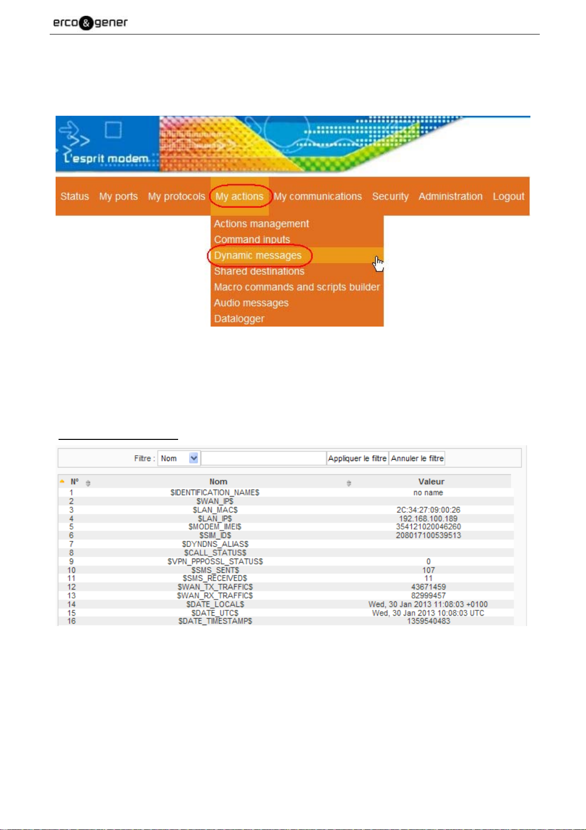
EG_GenIP30i_1016_UG_004_UK Page 54 / 143
5.2.7 Dynamic messages
To access the messages click on "My actions" and then drag the mouse over "Dynamic messages"
5.2.7.1 Identifications and states messages
The messages below correspond at identification of the GenIP. They cannot be changed.
Identifications messages list
Descriptions and non-contractual illustrations in this document are given as an indication only.
ERCOGENER reserves the right to make any modifications.
Dct_427_02
Page 55

EG_GenIP30i_1016_UG_004_UK Page 55 / 143
5.2.7.2 Systems messages
The System messages below are used by the GenIp. These can be changed via the web interface, the
control port Service port (default: 1224) or via macro command.
Some messages that correspond to the entries are read-only.
All massages can be changed except 133-139
Once entered and validated, these messages are saved automatically.
Descriptions and non-contractual illustrations in this document are given as an indication only.
ERCOGENER reserves the right to make any modifications.
Dct_427_02
Page 56

System messages list
EG_GenIP30i_1016_UG_004_UK Page 56 / 143
Descriptions and non-contractual illustrations in this document are given as an indication only.
ERCOGENER reserves the right to make any modifications.
Dct_427_02
Page 57

EG_GenIP30i_1016_UG_004_UK Page 57 / 143
5.2.7.3 Users messages
The Users messages below are for the user. They can be changed via the web interface, the control port
Service port (default: 1224) or the macro command.
Unlike identifications messages and systems messages, these messages are not saved.
$ message_name$ is case sensitive (Respect the lowercase and UPPERCASE).
Example :
set custom 0 ercogener ;end; load the text ercogener in the slot 0
set custom 0 ercogener;end;
OK
get custom 0 ;end; ask to GenIP sent the content of slot 0
get custom 0
ercogener
OK
Descriptions and non-contractual illustrations in this document are given as an indication only.
ERCOGENER reserves the right to make any modifications.
Dct_427_02
Page 58

Users messages list
EG_GenIP30i_1016_UG_004_UK Page 58 / 143
Descriptions and non-contractual illustrations in this document are given as an indication only.
ERCOGENER reserves the right to make any modifications.
Dct_427_02
Page 59

EG_GenIP30i_1016_UG_004_UK Page 59 / 143
5.2.8 Script
Curently it is possible to write script in GenIP language and PHP language.
The maximum capabilities in GenIP language is 35 K octets.
The maximum capabilities in PHP language is 100 K octets.
5.2.8.1 Creation of a script in GenIP language
A script is a sequence of macro commands for performing an operation.
They can be created from:
- The web interface (see below),
- A text editor and then imported.
Click on "My actions" and then drag the mouse to "Macro commands and scripts builder"
In the field "Add or edit a script", set the name of the script.
Descriptions and non-contractual illustrations in this document are given as an indication only.
ERCOGENER reserves the right to make any modifications.
Dct_427_02
Page 60
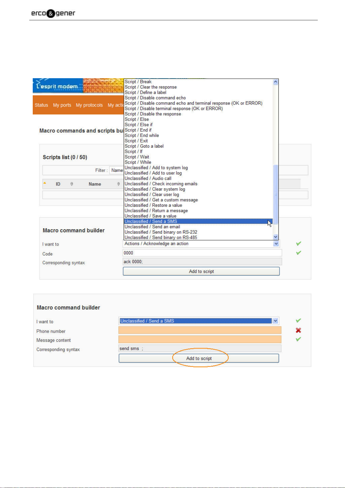
EG_GenIP30i_1016_UG_004_UK Page 60 / 143
Using the macro command builder
In the list "I want to" select the action to complete,
fill in the fields that appear,
then "Add to script".
Descriptions and non-contractual illustrations in this document are given as an indication only.
ERCOGENER reserves the right to make any modifications.
Dct_427_02
Page 61
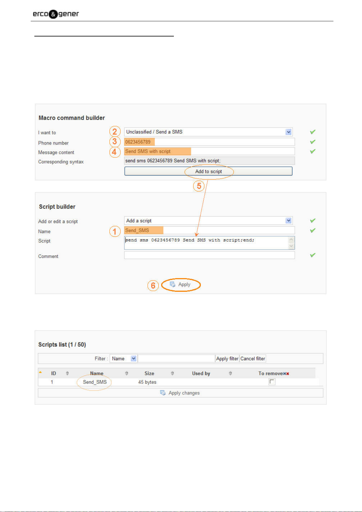
EG_GenIP30i_1016_UG_004_UK Page 61 / 143
Example of creating a script for sending an SMS
1 - Set the name of the script,
2 - In the list choose "Unclassified / Send a SMS",
3 - Inform the telephone number,
4 - Fill in the message content,
5 - "Add to script",
6 - "Apply".
The script is added in the "Scripts list (1/50)". It can be used.
Descriptions and non-contractual illustrations in this document are given as an indication only.
ERCOGENER reserves the right to make any modifications.
Dct_427_02
Page 62

EG_GenIP30i_1016_UG_004_UK Page 62 / 143
5.2.8.2 Creation of a script in PHP language
See to PHP manuel.
5.2.8.2.1 Header function dedicaded to GenIP
<?php
$stringsys=systemelog;
$stringuser=systemeuser;
$stringdata=systemeData;
send_to_system_log($stringsys);
send_to_user_log($stringuser);
send_to_data_log(phplog, $stringdata);
// execute a defined action
// call the action using the name defined in the actions management page
run_action("send_a_test_SMS");
// read / write modbus function
// data type : INT - UINT - FLOAT - STRING - HEX - BIT
$Valeur=read_modbus_value(02,01,1600,8,BIT);
set_variable_value("CUSTOM_MESSAGE_2",$Valeur);
write_modbus_value(02,15,1600,8,BIT,10000100);
// getter / setter for genip variables
set_variable_value("CUSTOM_MESSAGE_3",Sauv);
// save / restore a genip variable
save_variable("CUSTOM_MESSAGE_3");
//set_variable_value("CUSTOM_MESSAGE_63",$CUSTOM_MESSAGE_3);
restore_variable("CUSTOM_MESSAGE_4","123");
//set_variable_value("CUSTOM_MESSAGE_62",$CUSTOM_MESSAGE_4);
// getter / setter for logic pins
//function get_logic_output($logic_pin)
//function set_logic_output($logic_pin, $value)
// getter / setter for analogic current pins
//function get_analog_current_value($analog_pin)
//function set_analog_current_value($analog_pin, $value)
// getter / setter for analogic voltage pins
//function get_analog_voltage_value($analog_pin)
//function set_analog_voltage_value($analog_pin, $value)
?>
Descriptions and non-contractual illustrations in this document are given as an indication only.
ERCOGENER reserves the right to make any modifications.
Dct_427_02
Page 63

EG_GenIP30i_1016_UG_004_UK Page 63 / 143
5.2.8.3 Sequence of script
The GenIP 30i provides the possibility to create up to 50 scripts.
By default, the sequence of scripts is sequential. It means that a script can operate only if the current script is
completely done.
The GenIP 30i provides the possibility to proceed to a sequence of several scripts in parallel. It means that
they operate at the same time.
This parameter can be set through the hidden WEB page at the IP address of the GenIP
http://vvv.xxx.yyy.zzz/macro_command_builder_advanced.php
For the use of this function, make sure that there is no incompatibility between the scripts.
For example: a script sends a file to a server, another script cuts the WAN link.
1 – Define the number of scripts to be executed simultaneously.
If you set to 1 and during the script run, you wish to execute a macro command for example
loading a custom message, this action will be execute after the end of the script. To avoid this
set more 1.
2 – Adjust the "Max executed command count protection". This protection acts like a watchdog to avoid
any blocking. Once the number of commands executed in the script is reached, this one is stopped.
This value must be correctly adjusted.
As soon as this value is reached, the script is immediately stopped.
Descriptions and non-contractual illustrations in this document are given as an indication only.
ERCOGENER reserves the right to make any modifications.
Dct_427_02
Page 64

EG_GenIP30i_1016_UG_004_UK Page 64 / 143
Example:
The action on input 1 executes the script-1 which sends a file to a server.
The action on input 2 executes the script-2 which sends a SMS
Sequential Access
Parallel Access
Application :
In the script below, information is sent to a server in function of the value of CUSTOM_MESSAGE_0. A
second script must run in parallel, which updates the value of CUSTOM_MESSAGE_0.
while $CMP_#$CUSTOM_MESSAGE_0$#==#10#$;
wait 5;
send tcp 192.168.100.37:100 toto;
end while;
end;
The number of instances of the script interpreter must be at least 2.
See § 5.2.8.2 Sequence of script
Descriptions and non-contractual illustrations in this document are given as an indication only.
ERCOGENER reserves the right to make any modifications.
Dct_427_02
Page 65

EG_GenIP30i_1016_UG_004_UK Page 65 / 143
5.2.9 IP Information
5.2.9.1 LAN IP Address managed by the GenIP 30i
Today, the GenIP 30i recognizes the following ranges IP address:
• 192.xxx.xxx.xxx
• 172.xxx.xxx.xxx
• 132.xxx.xxx.xxx
• 10.xxx.xxx.xxx
5.2.9.2 GenIP 30i in DHCP server
In the case where the GenIP 30i is in DHCP server, the attributed lease is 2 days.
DHCP range should be before or after the IP address of the GenIP 30i, it should not be any overlap with the
IP address of GenIP 30i.
The choice of the address assignment of IP address based on the MAC must be within the IP range of the
DHCP range.
By default, the subnet mask is 255.255.255.0
The gateway address transmitted is the one registered in "IP Address of the network gateway" of the
GenIp.
5.2.9.3 GenIP 30i as Client DHCP
For the gateway address corresponding to the LAN on which the GenIP 30i is connected, it will have to be
entered manually on the Web interface of the GenIP 30i.
The GenIP 30i does not require the network gateway.
Descriptions and non-contractual illustrations in this document are given as an indication only.
ERCOGENER reserves the right to make any modifications.
Dct_427_02
Page 66

EG_GenIP30i_1016_UG_004_UK Page 66 / 143
5.2.9.4 Definition of Masquerade
When the masquerade is active, the WAN address obtained by the GenIP 30i is replaced by the GenIP 30i
address on LAN side. This function is used when the equipment connected on the LAN network cannot
provide the gateway address.
When this function is not active, the WAN address is presented on LAN side.
5.2.9.5 Ports management
For some services, there are some mirror ports. These mirror ports can not be modified and are used in
certain cases for remote accesses via GPRS or Data PPP. In local you have to use the ports by default.
The GenIP 30i provides the following functions:
• Redirection of port
In this case, an external port is put in relation with a local port.
In this case, the external equipment and the local equipment are clients for the GenIP 30i.
• Port Forwarding
In this case, we put in relation an external port and a local port which is associated to a local IP
address.
This allows to put a server equipment on local; then, via the WAN IP address and the external port,
we can access this equipment.
Today it is not possible to put a client equipment on LAN side in the case of a Port monitoring rule.
5.2.9.6 Incoming PPP connection
The GenIP 30i provides the RAS Server function.
To accede it, a client RAS session has to be created on the remote side.
The user name is ppp_in
The password is the one defined in the Web interface on the section modem.
During the PPP connection, the addresses are:
• GenIP 30i : 10.10.10.1
• The RAS client: 10.10.10.2
• We can define a limit of life time of this connection via the Web interface.
5.2.9.7 Outgoing PPP connection
Today the email service is not available in Data PPP connection mode.
Descriptions and non-contractual illustrations in this document are given as an indication only.
ERCOGENER reserves the right to make any modifications.
Dct_427_02
Page 67

EG_GenIP30i_1016_UG_004_UK Page 67 / 143
5.2.10 Time out of connection and disconnection on TCP service
Services Time Out or Disconnection
Web
After 3 minutes with no action, the led CONF turns off and another
user can connect on the GenIP 30i.
Service Port After 5 minutes with no activity, the port released.
RS232 service Port
RS485 service Port
During a change of parameter RS232 on the Web interface, the
TCP session is closed.
During a change of parameter RS485 on the Web interface, the
TCP session is closed
5.2.11 PIN code and SIM card management
In the case where the SIM card has a PIN code, it has to be entered in the field of the Web interface.
Inserting the SIM card when the GenIP 30i is ON requires a rebooting of the GenIP 30i.
5.2.12 Reloading a configuration from a backup file
From version V360, the saved configurations cannot be loaded into GenIP 30i with an earlier
version.
If we are for example in IP 192.168.100.104 and if we load a configuration whose IP address IP was
192.168.100.147; we have the possibility to keep the current LAN parameters or to accept the new
parameters. If you accept them, your parameters must be positioned in accordance with the ones of the
GenIP 30i.
When we change only the IP address of the GenIP 30i, the Web interface of the GenIP 30i will be accessible
again with the new IP address of the GenIP 30i.
• The led CONF turns OFF once the GenIP is available again.
• On the Web interface, each validation saves the information in the GenIP 30i.
• After configuration change, the GenIP will be operating after 2 seconds.
• In some cases, it is necessary to reboot the GenIP 30i. In case of doubt, do not
hesitate to reboot the GenIP 30i.
Descriptions and non-contractual illustrations in this document are given as an indication only.
ERCOGENER reserves the right to make any modifications.
Dct_427_02
Page 68

EG_GenIP30i_1016_UG_004_UK Page 68 / 143
5.2.13 Notes about the definition and the behavior of the actions
An action with no acknowledgement request can lead to one or several other actions in the following cases:
• Action in parallel
• Action if success (An action is considered as a success if it succeeded) (Example SMS sent, WAN
connection established...). A non-acknowledgement of an action does not consider the action as a
failure.
• Action if failure. This action occurs when the action fails.
Some action are not possible at the same time, it depends on the communication status of the
socket. For example, in the case of a permanent WAN connection, it is not possible to establish
in parallel a GSM Data connection.
An action with acknowledgement request can lead to one or several other actions in the following cases:
• Action in parallel
• Action if success (An action is considered as a success if it succeeded) (Example SMS sent, WAN
connection established...). A non-acknowledgement of an action does not consider the action as a
failure.
• Action if failure. This action occurs when the action fails.
• Spare action. This action occurs in case of a non-acknowledgement of the action.
5.2.14 Loss and recovering of network (LAN)
The GenIP waits for the time of filtering before doing an action in case of cut and recovering.
This action is managed whatever the status of the GenIP can be: Client Server DHCP or Static
Descriptions and non-contractual illustrations in this document are given as an indication only.
ERCOGENER reserves the right to make any modifications.
Dct_427_02
Page 69

EG_GenIP30i_1016_UG_004_UK Page 69 / 143
5.2.15 Remarks about GSM/WAN/SMS connections
Firstly, these services are under a good GSM network.
In weak GSM reception mode, we can consider that the SMS service is the most adapted to
send information. But careful, in SMS mode, we are subjected to a passage via a SMS server
center and in some cases, it can lead to a certain time for the information transmission.
Concerning the GSM Data, we are in point to point Data bi-directional (avis V32/9600) mode. In this case,
check your subscription conditions with your operator. Also you must choice 2G connection into Gen IP
setting.
In the case of WAN, we are on a TCP/IP base with dynamic or fixed IP addresses depending on your
subscription conditions with your operator.
In this case, your operator gives you an APN or a public or private access point.
It is advised to inform yourself about connection rules (time of connection limited as well as on ports
supported in TCP/UDP/FTP/HTTP... depending on subscriptions and operators.).
5.2.16 Remarks of WAN connection disconnection of the GenIP 30i
The GenIP works with a connection disconnection meter which can be visualized on the system log.
If for example you launch two WAN connections and only one disconnection, then the GenIP will remain
connected to the WAN network as its connection meter did not come back to zero. To come back to zero,
another disconnection will be necessary.
When we ask for two successive connections without disconnection between these two
requests, we keep the first WAN IP address given by the WAN network.
Concerning the WAN connection, the GenIP has an embedded internal function of permanent connection to
compensate for possible cut of the WAN network. The time for automatic reconnection depends on the
coverage conditions when the cut occurs.
In the case of a temporized connection, if we ask for a disconnection before the end of the temporization,
then the temporization comes back to zero and the WAN connection disappears.
Descriptions and non-contractual illustrations in this document are given as an indication only.
ERCOGENER reserves the right to make any modifications.
Dct_427_02
Page 70

EG_GenIP30i_1016_UG_004_UK Page 70 / 143
5.2.16.1 Connect disconnect WAN link in the script
If you want a script make a WAN connection for to send multiple email without increasing the counter, you
must use connect_me_to_wan_now. After connecting, sending all mail will be made.
In this case it is necessary to use disconnect_me_from_WAN_now after sending mails to
close the WAN connection
If you use several do action 'Send mail', during the time of the connection the sending action
will be initiated and there is a risk that the counter is greater than 1, in this case WAN
disconnection will not be performed.
5.2.17 Remarks concerning the clock management
The GenIP is equipped with a real time clock (HTR) which is saved by battery.
The time setting is possible via the link LAN or WAN. In this case, we can use:
• The clock of the computer connected to the GenIP 30i
• A NTP server via the gateway LAN or the WAN
The GenIP takes the UTC time for the time management.
On the Web interface, when you are in the time menu, you are in real time. Consequently, the available
choices depend on the status of the GenIP 30i.
For example, if the GenIP is connected in WAN, you will have the choice to set the clock via WAN, otherwise
the option will not be available. Also if you informed the gateway and the server the network name (DNS) you
will have the possibility to go through the network gateway.
5.2.18 Remarks concerning the management of the network gateway or LAN
When the GenIP is connected on a LAN, it can use the gateway of the LAN for the time setting or to be
accessed from the outside (if the LAN parameters authorize it).
In the case of an external access, it will be possible via the LAN gateway if the GenIP is not in WAN
connection. In fact, in the case where the GenIP is connected in WAN, by default this is this WAN access
which has priority. So if we want to reach the GenIP via the LAN gateway, the GenIP must be disconnected
from the WAN.
A change in the bridge requires a reboot of the GenIP 30i.
Descriptions and non-contractual illustrations in this document are given as an indication only.
ERCOGENER reserves the right to make any modifications.
Dct_427_02
Page 71

EG_GenIP30i_1016_UG_004_UK Page 71 / 143
5.2.19 Remarks concerning the management of the DNS service
By default, in the GenIP, the address of the DNS server entered in the Ethernet parameters is 8.8.8.8.
The DNS was chosen because it is not locked with any operator. It can be used regardless of SIM card. This
is the "google" DNS.
It is the same for the DNS to 8.8.4.4.
If you want to change this DNS by the DNS of your FAI, you have to do a WAN connection, to recover this
address on the system log and to integrate it on the Ethernet parameters.
5.2.20 Remarks concerning the tools
The GenIP 30i provides some analysis or tracks tools like bytes meter, signal level measure, possibility to
track some modem commands, manual ping.
These tools are indicators and cannot be considered sufficient in the case of precise measures.
5.2.20.1 Bytes meter
There is a byte meter on the LAN and a byte meter on the WAN. These meters can be put back to zero
through the menu administration and tool, or by restarting the product.
In the case of an estimation concerning the WAN compared with a precise action, it is advised to:
• Program only the concerned action on the GenIP
• Cancel the Ping and TCP connection for keep alive and connection.
• Unvalidate the gateway address from your computer if it uses the address of the GenIP 30i
Your connected equipment can generate traffic. (For example Windows automatic update)
5.2.20.2 Modem commands tracks
It is possible to recover the commands exchanged between the Linux and the communicating part.
This occurs via a UDP link orientated towards a port and a machine address present on the LAN.
Descriptions and non-contractual illustrations in this document are given as an indication only.
ERCOGENER reserves the right to make any modifications.
Dct_427_02
Page 72

EG_GenIP30i_1016_UG_004_UK Page 72 / 143
5.2.20.3 System log tracks
It is possible to recover the tracks of the system and user diary via a UDP link orientated towards a port and
a machine address which present on the LAN.
If this function is not active, it is still possible to download the log.
5.2.21 Remarks concerning Allowed sources
By default, no sources are authorized in order to avoid inopportune connections
In the case of authorization and in order to avoid problems of excessive communications, you
must fill the only authorized sources.
For example, if you authorize all sources and if you receive advertising, the GenIP will reply
with a non-acknowledgement and you will be invoiced.
5.2.21.1 Unwanted connections BlackList
To protect against unwanted connections, after receiving three unauthorized sources, the GenIP block the
response. Example of Ping Pong SMS with an advertising server.
The BlackList will be deleted automatically upon receipt of an authorized source.
5.2.22 Remarks about tunnels
It is possible to establish 2 kinds of tunnels:
Tunnel SSL
Tunnel IPSec manual or IKE.
It is not possible to use the 2 kinds of tunnels together. If you use the SSL, do not forget to un-validate the
IPSec tunnel(s).
By default, it is set with examples of IPSec tunnels, and the action of establishing the SSL tunnel is defined.
The GenIP does not support both manual IPsec tunnels and IKE
Descriptions and non-contractual illustrations in this document are given as an indication only.
ERCOGENER reserves the right to make any modifications.
Dct_427_02
Page 73

EG_GenIP30i_1016_UG_004_UK Page 73 / 143
5.2.22.1 SSL Tunnel
The GenIP allows to open only one tunnel at the same time.
All information is directed inside the tunnel, consequently when the tunnel is open, only the SMS function
remains available. All other functions that do not use the SSL tunnel is not available.
For the installation, see the application note AN068, or use the action defined by default.
Aim of the defined action:
• Create a SSL tunnel between 2 GenIP using the SMS service.
Principle of use of the defined action:
• Between the 2 GenIP, one will be considered as the Server and the other one as the Client
• The GenIP server will connect to the WAN and will indicate to the GenIP client to connect to the
WAN and to establish a SSL tunnel towards the GenIP server
• For that, you will have to:
o On the side of the GenIP client, you must authorize the telephone number of the GenIP
server, in the field of the allowed sources.
o You must have 2 different sub-network (In our case, it will be 192.168.100.0 and
192.168.2.0).
o Start client
o On server’s side, launch the action «VPN_SSL_Automatic_Connexion_by_SMS ».
o Wait until the GSM LEDs flash quickly at each end and do the test with the ping.
Descriptions and non-contractual illustrations in this document are given as an indication only.
ERCOGENER reserves the right to make any modifications.
Dct_427_02
Page 74

EG_GenIP30i_1016_UG_004_UK Page 74 / 143
5.2.23 Data Logging
There are 10 different records (USB and internal memory) with a limit size for each record:
- 1 MB internal memory (10 MB total)
- 1 GB on USB key (10 GB total)
5.2.24 IPSec Tunnel
The GenIP allows to open 5 tunnels at the same time.
Compared with the SSL tunnel, there is no restriction concerning the outgoing functions. Only the restriction
below has to be taken into account.
If a rule is defined towards a remote site, all exchanges with this remote site are encrypted. For example, if
you have defined a rule concerning your ADSL, and if you try to ping the WAN IP address of the GenIP, you
will have no response. The same thing will occur if you try to make a remote access to the Web interface. To
access it, you will have to go through the tunnel.
For example, your GenIP has the LAN address 192.168.3.100 and the WAN address 94.90.10.120. If the
rule IPSec is active, the way to ping or access to the GenIP will be to set the address 192.168.3.100. If the
rule IPSec is inactive, we will set 94.90.10.120
Aim of the tunnels defined by default:
• To create an IPSec tunnel between 2 GenIP using the SMS service.
• To create an IPSec tunnel towards a router
1) Principle of use of the IPSec manual tunnel between 2 GenIP:
For the installation, see the application note AN081, or use the tunnels already defined by default.
• The 2 GenIP will use the le SMS service. A GenIP will be considered as the Local
(192.168.100.xxx) and the other one as the Remote (192.168.2.xxx).
• The 2 GenIP will connect to the WAN and will send themselves their WAN IP addresses
• For that, you will need to :
o On each GenIP, authorize the telephone number of the other GenIP, in the field of the
authorized sources.
2) Principle of use of the IPSec (manual or IKE):
For the installation, see the application note AN132.
Descriptions and non-contractual illustrations in this document are given as an indication only.
ERCOGENER reserves the right to make any modifications.
Dct_427_02
Page 75

EG_GenIP30i_1016_UG_004_UK Page 75 / 143
5.2.25 User Management and Password
This menu is used to set "Users" who have access to GenIP 30i.
5.2.25.1 Creating a User
Enter the different fields and "Apply"
In the fields "Name" and "Password" use only the characters
- A à Z
- a à z
- 0 à 9
-&(_@)=+*!:/.,?<> -
Once created, the user is listed.
The "Comment" appears in a tooltip when you mouse is over the user.
(See example below).
Descriptions and non-contractual illustrations in this document are given as an indication only.
ERCOGENER reserves the right to make any modifications.
Dct_427_02
Page 76
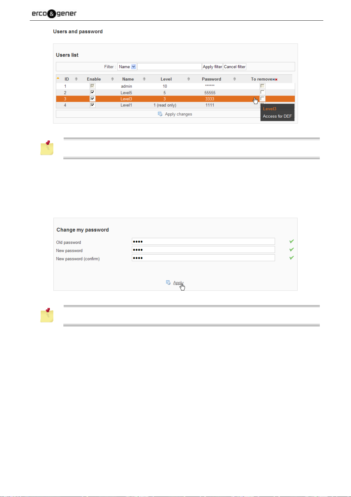
EG_GenIP30i_1016_UG_004_UK Page 76 / 143
The maximum number of users is 20
5.2.25.2 Change Password
Enter the old password, the new password, confirm the password and then "Apply".
Only the "User" connected can change their password.
5.2.25.3 Hierarchy
There are two possible levels of hierarchy:
Level 1 ............. : Read access only.
Level 2-10 ........ : Read access, write to create, edit scripts, settingsGenIP 30i.
Descriptions and non-contractual illustrations in this document are given as an indication only.
ERCOGENER reserves the right to make any modifications.
Dct_427_02
Page 77

EG_GenIP30i_1016_UG_004_UK Page 77 / 143
You cannot create or delete a user level 10. It is frozen and remains unique.
A level user X can create, delete a user of a lower level.
Once created, the password of a user Y can be modified, by logging as Y.
In the example below the "User5" can:
- Create users level 1 to 4
- Delete Users 3 and 1
In the example below "User1" "is connected to GenIP 30i.
He can only do the consultation and cannot change his "Password"
Descriptions and non-contractual illustrations in this document are given as an indication only.
ERCOGENER reserves the right to make any modifications.
Dct_427_02
Page 78

EG_GenIP30i_1016_UG_004_UK Page 78 / 143
5.2.26 Remarks about the function Bridge
The GenIP provides the Bridge function between the RS ports.
The possible combinations are:
RS232 RS232
RS485 RS485
RS232 RS485
NB: We cannot make a RS towards two RS.
We cannot make a RS towards two RS.
During the connection and the bridge logout, it is possible to generate a message on the RS.
During a request of WAN Disconnection, the message will arrive within 2 minutes.
On the other cases, the time depends on the time of network connection for the connection message.
5.2.27 Hardware Option
For some options of the GenIP, it is necessary to declare them in the hidden web page at the current IP
address of the GenIP http://vvv.xxx.yyy.zzz/hardware_options.php
For this check the box setting.
After validation a pop up appears.
Descriptions and non-contractual illustrations in this document are given as an indication only.
ERCOGENER reserves the right to make any modifications.
Dct_427_02
Page 79

EG_GenIP30i_1016_UG_004_UK Page 79 / 143
5.2.28 Inactivity Timer
It is possible using the system message $WAN_TX_TRAFFIC$, $WAN_RX_TRAFFIC$ (see § 5.2.7.2
Systems messages) and using a script to create a inactivity timer on the traffic of the WAN link.
Application :
In this example below a counter of 10 seconds is initiated by an action and it is refreshed every second.
Once there is no traffic on the WAN link for 10 seconds, the WAN connection is disconnected.
For this create 2 actions
st
action : StartTimer qui appelle le script ci-dessous.
1
nd
action : StartConnexionWan initiates the WAN link and when this action is successful, it call
2
StartTimer.
Script : :
GV_Timer=10;
while $CMP_#$GV_Timer$#!=#0#$;
if $OR_#$CMP_#$WAN_RX_TRAFFIC$#!=#$GV_Rx_Traffic$#$#
$CMP_#$WAN_TX_TRAFFIC$#!=#$GV_Tx_Traffic$#$#$;
GV_Timer=10;
else if $CMP_#$GV_Timer$#>#0#$;
GV_Timer=$SUB_#$GV_Timer$#1#$;
If $CMP_#$GV_Timer$#==#0#$;
wan disconnect;
end if;
end if;
GV_Tx_Traffic=$WAN_TX_TRAFFIC$;
GV_Rx_Traffic=$WAN_RX_TRAFFIC$;
wait 1;
end while;
end;
The number of instances of the script interpreter must be at least 2.
See § 5.2.8.2 Sequence of script.
Descriptions and non-contractual illustrations in this document are given as an indication only.
ERCOGENER reserves the right to make any modifications.
Dct_427_02
Page 80

EG_GenIP30i_1016_UG_004_UK Page 80 / 143
5.3 Information about the function ModBus
The GenIP offers the possibility of gateway ModBus RTU ModBus TCP on the links RS, LAN and WAN and
it also includes the following features.
• Modbus master. This function is under the form of a dynamic variable. It can be integrated inside the
message of a SMS, an email or TCP. The result can be posted on a FTP or TCP server, data-logged
in a file stored on USB or in the flash memory or send to SMS or Mail.
• Modbus slave. This function interacts with the digital and analog inputs/outputs (reading, writing); it allows
to trigger some actions predefined on the web interface, and to execute some macro commands.
The configuration of the functions Modbus and I/O can be done only via the web interface.
It is not possible to modify the I/O configuration by Modbus frames. However, it is accessible in reading
mode only on the Modbus slave.
Descriptions and non-contractual illustrations in this document are given as an indication only.
ERCOGENER reserves the right to make any modifications.
Dct_427_02
Page 81

EG_GenIP30i_1016_UG_004_UK Page 81 / 143
Access to the different parameters of configuration of the Modbus "Mes protocoles/Modbus" (My
protocols/Modbus)
Then, cross the case "Modbus"
Descriptions and non-contractual illustrations in this document are given as an indication only.
ERCOGENER reserves the right to make any modifications.
Dct_427_02
Page 82

EG_GenIP30i_1016_UG_004_UK Page 82 / 143
5.3.1 Configuration
List of configuration parameters associated to the slave Modbus:
• Modbus slave address: 01 – 247.
• Listening port TCP, internal on the GenIP. The selection of this port is provided to the user in order not
to conflict with a port number that he wants to affect to another function.
• Access to the function Modbus slave via the Web interface :
• Security code used to authorize the triggering of action and the implementation of macro commands.
• Configuration of the analog Inputs/Outputs in current or tension.(MesPorts/Entrées et sorties) (My
ports/Inputs and Outputs).
• Creation of action.(Mes actions/Paramétrage des actions) (My actions/Setting the actions).
• Creation of macro commands.(Mes actions / Constructeur de macro commandes et de scripts) (My
actions / Builder of macro commands and scripts).
For more information, download on our website http://www.ercogener.com/modem-routeurpasserelle-industriel-rail-din-genip-20i.html#applications the applications notes:
Configuration of the RS232 serial link
Descriptions and non-contractual illustrations in this document are given as an indication only.
ERCOGENER reserves the right to make any modifications.
Dct_427_02
Page 83

EG_GenIP30i_1016_UG_004_UK Page 83 / 143
Configuration of the RS485 serial link
Configuration of the link TCP gateway Modbus
List of Modbus equipments defined on the gateway (Example)
Descriptions and non-contractual illustrations in this document are given as an indication only.
ERCOGENER reserves the right to make any modifications.
Dct_427_02
Page 84
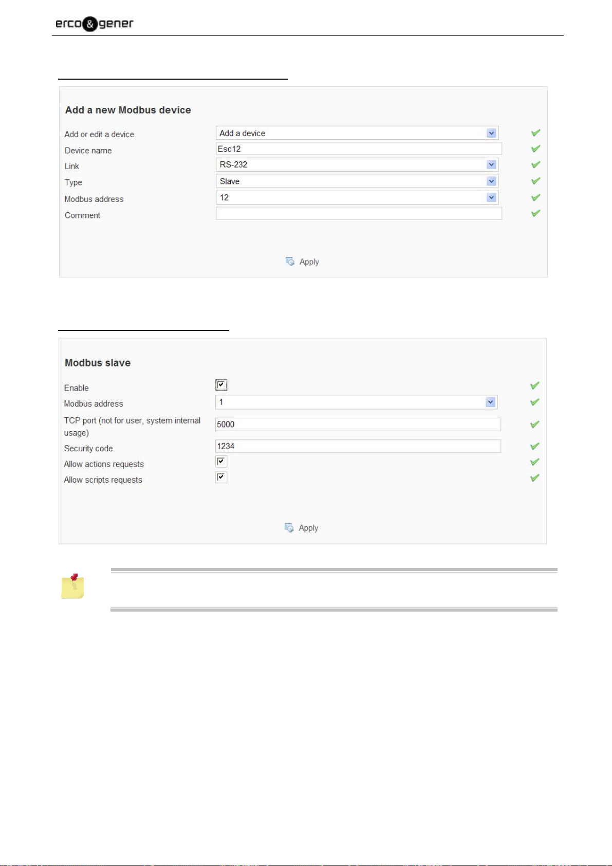
EG_GenIP30i_1016_UG_004_UK Page 84 / 143
Creation of Modbus equipment for the gateway
Setting the GenIp in Modbus slave.
Security code allows to secure the access to the actions and macro commands.
Descriptions and non-contractual illustrations in this document are given as an indication only.
ERCOGENER reserves the right to make any modifications.
Dct_427_02
Page 85

EG_GenIP30i_1016_UG_004_UK Page 85 / 143
5.3.2 Modbus Master
This function is under the form of a dynamic variable. It can be integrated in a message of a SMS, an email
or TCP server. The result can be posted on a FTP or TCP server, data-logged in a file stored on USB or in
the flash memory or send to SMS or Mail.
This variable can also be used in an action, compared with a fixed value in order to trigger an action or do a
macro-command.
The function Modbus master is permanently available. It activates when sending a request. All requests sent
by the master pass through the gateway Modbus. Consequently, you have to register the slaves which are
consulted in the page Mes protocoles->modbus (My protocols->modbus) of the web interface.
In the case where a master RS485 is declared and if the GenIP must send requests to slaves
on the RS485, it is possible that some collisions lead to the loss of the request.
5.3.2.1 Structure of the messages Modbus Master
The structure of the message or variable is as follows:
Field Description
$MODBUS
Delimiter of frame heading
Address of slave Modbus, this slave must be declared in the list of the slaves
@SLAVE
Modbus, or correspond to the slave address of the GenIP.
You can be used Custom Message Shared Destination or Dynamic Message.
CODEF
@REGISTER
Code Modbus function. Must belong to the list of function codes authorized (see §
5.3.2.2 Function Code authorized).
Address of the memory register of the slave Modbus to read. The value must be
decimal.
Number of registers Modbus to read. This value is conditioned to the type of
NBREGISTER
format of the response (cf. Format of data and number of registers that can be
read). The registers have a size of 16 bits. In the case of function codes Modbus
01 and 02, this value will be the number of bits to read.
FORMATRESPONSE
$
Format of presentation of the response. (for more details, see § 5.3.2.3
5.3.2.3 Format of data and number of registers that can be read)
Delimiter end of frame
Each field is separated by an 'under score'
Descriptions and non-contractual illustrations in this document are given as an indication only.
ERCOGENER reserves the right to make any modifications.
Dct_427_02
Page 86

EG_GenIP30i_1016_UG_004_UK Page 86 / 143
Example
$MODBUS_02_03_00_01_UINT$
Allows to read a register at the address 0 of the slave Modbus address 2 by using the function code 3.
The return is of type entire not signed.
The variable is replaced by the character string ‘5982’.
Heading @SLAVE. CODEF @REGISTER
$MODBUS
02 03 00 01 UINT $
REGISTER
NB
FORMAT
RESPONSE
Delimiter
It is necessary to have an idea about the response expected.
For example: The expected result is 99084 (0x1830C) corresponding to 2 registers of 16 bits.
If the number of register is 1 and a format UINT the response returned is: 33548 (0x830C)
If the number of register is 1 and a format INT the response returned is: -31966 (0x830C)
In this case, the number of register must be 2.
5.3.2.2 Function Code authorized
Only the reading function codes are available.
• 0x01 Reading of N bits of output (See § 5.3.5.1 Reading of N bits of output)
• 0x02 Reading of N bits of inputs (See § 5.3.5.2 Reading of N bits of input)
• 0x03 Reading of N exploitation registers (See § 5.3.5.3 Reading of N registers of exploitation)
• 0x04 Reading of N inputs registers (See § 5.3.5.4 Reading of N registers of input)
For the codes 0x01 and 0x02 (reading of bit) the value returned is a multiple of 8 bits.
All the bits of the Modbus response are taken into account.
Example :
Value of registers (MSB, LSB) : 0xFF05
Reading of 10 bits returned : 0x0503
Descriptions and non-contractual illustrations in this document are given as an indication only.
ERCOGENER reserves the right to make any modifications.
Dct_427_02
Page 87

EG_GenIP30i_1016_UG_004_UK Page 87 / 143
5.3.2.3 Format of data and number of registers that can be read
The format of the response can be with the following format:
Format Description
Number of registers that can be read: 1, 2 or 4.
INT
Format: entire signed.
String of characters ascii.
Example : ‘5896’, ‘-986’
Number of registers that can be read: 1 to 4.
UINT
Format: entire not signed.
Example: ‘6952’
Number of registers that can be read: 1 to 64.
HEX
Format: hexadecimal value of the registers.
Example, for a value read of 35372, the character string will be ‘8A2C’.
Number of registers that can be read: 1 to 16.
Number of bits that can be read: 1 to 128.
BIT
Format: binary value of the registers.
Example for a value read of
‘103’ (8 bits), the character string displayed is ‘01100111’.
'1' (1 bit), the character string displayed is ‘00000001’.
Number of registers that can be read: 2 (float32) or 4 (float64).
FLOAT
Format: digit with floating comma.
Example: ’36,987’.
Number of registers that can be read: 1 to 64 registers.
Format: characters string. In this case, no conversion is done on the data read. The user
STRING
must ensure that the registers contain only characters that can be displayed.
Example: ‘Alarm’.
To reverse the reading direction of the register
With 0 ≤ n ≤ 3
Example: value of register in hex ’AC57BD13'.
Normal reading : modbus_11_3_0_2_hex = AC57BD13
INVERTED
Normal reading : modbus_11_3_0_2_invertedhex = 13BD57AC
INVERTEDn
INVERTED0
Normal reading : modbus_11_3_0_2_inverted0hex = AC57BD13
INVERTED1
Reverse reading : modbus_11_3_0_2_inverted1hex = 13BD57AC
INVERTED2
Reverse reading : modbus_11_3_0_2_inverted2hex = 57AC13BD
INVERTED3
Reverse reading : modbus_11_3_0_2_inverted3hex = BD13AC57
Descriptions and non-contractual illustrations in this document are given as an indication only.
ERCOGENER reserves the right to make any modifications.
Dct_427_02
Page 88

EG_GenIP30i_1016_UG_004_UK Page 88 / 143
5.3.2.4 Example of use of a variable
The dynamic variable Modbus can be used in any action that sends a message.
For example, to send the Modbus response by SMS, email, TCP/UDP, ftp in a text file.
It is also possible to data log the responses in a file stored on a USB key or inside the flash memory of the
GenIP.
Example of transmission of the Modbus response towards SMS
Create an action which sends a SMS; the content of the message will be for example:
GenIp_Site_North:$MODBUS_01_01_00_02_UINT$
This action will be triggered upon the change of status of a logical output.
SMS received: GenIp_Site_North:0003 (003 is the read value).
Descriptions and non-contractual illustrations in this document are given as an indication only.
ERCOGENER reserves the right to make any modifications.
Dct_427_02
Page 89

EG_GenIP30i_1016_UG_004_UK Page 89 / 143
Data-logging Example
Create a file of data-logging, in the page My actions->Data logger.
Create an action which adds a message to a data registration, by selecting the file previously created. The
content of the message can be:
$DATE_LOCAL$GenIp_Site_North:$MODBUS_01_01_00_02_UINT$$CR$$LF$
Create a periodic event in Administration->Time which calls the action previously created.
Descriptions and non-contractual illustrations in this document are given as an indication only.
ERCOGENER reserves the right to make any modifications.
Dct_427_02
Page 90

EG_GenIP30i_1016_UG_004_UK Page 90 / 143
The event created is cyclically called. At each execution of the action, a line will be added in the USB key.
Example of Comparison
Create a script:
$IF_$CMP_$MODBUS_01_03_00_01_UINT$_== 3$ #send sms 0102030405 Door Open GenIp Site
North##;end;
When the read value of the register 00 of the slave at the address 01 is equal to 0001, the message Door
open GenIp Site North is sent via SMS. In the contrary case, no action is done.
In the case where the slave Modbus does not respond, the script is not executed and the message below is
written in the system diary:
"$IF_$CMP_$MODBUS_01_03_00_01_UINT$_== 3$ #send sms 0102030405 Door Open GenIp Site
North##;" is not a valid command"
Descriptions and non-contractual illustrations in this document are given as an indication only.
ERCOGENER reserves the right to make any modifications.
Dct_427_02
Page 91

EG_GenIP30i_1016_UG_004_UK Page 91 / 143
List of operators can be used
Operator Description
== equality
!= non equality
< lesser
<= lesser or equal
> greater
>= greater or equal
5.3.3 Structure of messages Modbus RTU
Request
Designation
Size
Example *
@ Slave Function code @ register Nb register to read CRC 16
1 Byte 1 Byte
2 Bytes
Msb - Lsb
2 Bytes
Msb - Lsb
01 03 1000 0001 80CA
* Request of reading of 1 byte of the register at the address 1000 of the slave at the address 01
Response of a request
Designation
Size
Example *
@ Slave Function code @ register Nb register to read CRC 16
1 Byte 1 Byte 1 Byte
01 03 02 0030 B850
2 Bytes
Msb - Lsb
* Response to the previous request.
The number of byte to follow does not take into account the 2 bytes of the CRC16.
2 Bytes
Msb - Lsb
2 Bytes
Msb - Lsb
Example
Request of reading of 4 registers from the address 1000 of the slave at the address 01
@ Esc Fct. Code @ Reg. Nb of register to read CRC 16
Request
01 03 1000 0004 40C9
@ Esc Fct. Code Nb byte Data 1 Data 2 Data 3 Data 4 CRC 16
Response
01 03 08 0030 0034 0045 0016 840B
Descriptions and non-contractual illustrations in this document are given as an indication only.
ERCOGENER reserves the right to make any modifications.
Dct_427_02
Page 92

EG_GenIP30i_1016_UG_004_UK Page 92 / 143
5.3.4 Structure of messages Modbus TCP
The message Modbus TCP is made of a heading TCP followed by the classical frame Modbus RTU without
CRC.
Request
Designation TCP Idle Protocol Nb of byte to follow Modbus Frame without CRC
Size 2 Bytes 2 Bytes 2 Bytes n Bytes
Example *
0001 0000 0006
010200000001
TCP Idle ........................ : This identification is provided by the Master.
Protocol ......................... : The protocol code Modbus is 0000.
Nb of byte to follow ....... : The number of byte of the frame Modbus RTU.
Response of a request
Designation TCP Idle Protocol Nb of byte to follow Modbus Frame without CRC
Size 2 Bytes 2 Bytes 2 Bytes n Bytes
Example *
0001 0000 0004
01020100
5.3.5 Functions codes of the Modbus standards supported
Here, MSB and LSB concern the order of the bits of each byte.
For the bytes, the terms Hi and Lo are used.
All registers have a size of 16 bits.
5.3.5.1 Reading of N bits of output
Read of N bits of output
@Modbus slave
function code = 0x01
Bit Address Hi
Request
Bit Address bit Lo
Nb bit Ho
Nb bit Li
@Modbus slave
function code = 0x01
Nb byte Number of data that follow
Response
Data LSB
Data MSB
Address of the bit to read
Number of bit to read
...
Descriptions and non-contractual illustrations in this document are given as an indication only.
ERCOGENER reserves the right to make any modifications.
Dct_427_02
Page 93

EG_GenIP30i_1016_UG_004_UK Page 93 / 143
5.3.5.2 Reading of N bits of input
Read of N bits of input
@Modbus slave
function code = 0x02
Request
Address H
Address L
Nb bit H
Nb bit L
@Modbus slave
function code = 0x02
Nb bytes Number of data that follow
Response
Data LSB
Data MSB
...
5.3.5.3 Reading of N registers of exploitation
Read of N registers of exploitation
@Modbus slave
function code = 0x03
Address of the bit to read
Number of bit to read
Request
Response
Address Hi
Address of register to read
Address Lo
Nb reg Hi
Number of register to read
Nb reg Lo
@Modbus slave
function code = 0x03
Nb byte Number of data that follow
Data Hi
Value of the register
Data Lo
...
Descriptions and non-contractual illustrations in this document are given as an indication only.
ERCOGENER reserves the right to make any modifications.
Dct_427_02
Page 94

EG_GenIP30i_1016_UG_004_UK Page 94 / 143
5.3.5.4 Reading of N registers of input
Read of N registers of input
@Modbus slave
function code = 0x04
Request
Address H
Address L
Nb reg H
Nb reg L
@Modbus slave
function code = 0x04
Nb bytes Number of data that follow
Response
data Hi
Data Lo
...
5.3.5.5 Writing of 1 bit of output
Writing of 1 bit of output
Request
@Modbus slave
Function code = 0x05
Address of register to read
Number of register to read
Value of the register
Response
Address HI
Address LO
Data LSB
Data MSB
Idem request
5.3.5.6 Writing of 1 register of exploitation
Writing of 1 register of exploitation
Request
Response
@Modbus slave
Function code = 0x06
Address reg Hi
Address reg Lo
Data Hi
Data Lo
Idem request
Address of the bit to write
FF00 to put the output to ON
0000 to put the output to OFF
Address of the register to write
Value to write
Descriptions and non-contractual illustrations in this document are given as an indication only.
ERCOGENER reserves the right to make any modifications.
Dct_427_02
Page 95

EG_GenIP30i_1016_UG_004_UK Page 95 / 143
5.3.5.7 Writing of N bit of output
Writing of N bit of output
Request
Response
@Modbus slave
Function code = 0x0F
Address Hi
Address of the bit to write
Address Lo
Nb bits MSB
Number of bit to write
Nb bits LSB
Nb bytes Number of byte to write
Data Hi
Data Lo
Value to write
...
@Modbus slave
Function code = 0x0F
Address Hi
Address Lo
Nb bits Hi
Nb bits Lo
This function code is mainly used by the access of digital outputs.
Descriptions and non-contractual illustrations in this document are given as an indication only.
ERCOGENER reserves the right to make any modifications.
Dct_427_02
Page 96

EG_GenIP30i_1016_UG_004_UK Page 96 / 143
5.3.5.8 Writing of N registers of exploitation
Writing of N registers of exploitation
Request
Response
@Modbus slave
Function code = 0x10
Address Hi
Address of the register
Address Lo
Nb registers Hi
Number of consecutive register to write
Nb registers Lo
Nb bytes (Nb registers * 2) Number of byte that follow
Data0 Hi
Data0 Lo
Data1 Hi
Value to write
Data1 Lo
...
@Modbus slave
Function code = 0x10
Address Hi
Address Lo
Nb registers Hi
Nb registers Lo
Descriptions and non-contractual illustrations in this document are given as an indication only.
ERCOGENER reserves the right to make any modifications.
Dct_427_02
Page 97

EG_GenIP30i_1016_UG_004_UK Page 97 / 143
5.3.6 Error codes Modbus
The example below is given with the following slave address: 0x01
Designation
Size
Example
@ Slave Function Code Error Code CRC 16
1 Byte 1 Byte 1 Byte 2 Bytes Msb - Lsb
01 90 05 8C03
Code Name Description
The function code received in the query is not an allowable action
01 ILLEGAL FUNCTION
for the slave. If a poll Program Complete command was issued,
this code indicates that no program function preceded it.
02 ILLEGAL DATA ADDRESS
The data address received in the query is an allowable address
for the slave.
03 ILLEGAL DATA VALUE A value contained in the query is an allowable value for the slave.
04 SLAVE DEVICE FAILURE
An unrecoverable error occurred while the slave was attempting to
perform the requested action.
The slave has accepted a request and is processing it, but a long
duration of time is required. This response is returned to prevent a
05 ACKNOWLEDGE
timeout error from occurring in the master. The master can next
issue a Poll Program Complete message to determine if
processing is complete.
The slave is processing a long duration program command. The
06 SLAVE DEVICE BUSY
master should retransmit the message later when the slave is
free.
The slave cannot perform the program function received in the
07
NEGATIVE
ACKNOWLEDGE
query. This code is returned for an unsuccessful programming
request using function code 13 or 14 decimal. The master should
request diagnostic or error information from the slave.
The slave attempted to read extended memory, but detected a
08 MEMORY PARITY ERROR
parity error in the memory. The master can retry the request, but
service may be required on the slave device.
Descriptions and non-contractual illustrations in this document are given as an indication only.
ERCOGENER reserves the right to make any modifications.
Dct_427_02
Page 98

(1)
EG_GenIP30i_1016_UG_004_UK Page 98 / 143
5.3.7 Addressable memory of the GenIp
Address
0x0000
Simple inputs
Digital inputs
Ro
Counting inputs
0x0001 to 0x003F
0x0040 to 0x0043
0x0044 to 0x0047
0x0048 to 0x007F
0x0080
Digital outputs
R/W
Simple outputs
0x0081
0x0081 to 0x00BF
Not used 0x00C0 to 0x00FF Not used
Analog inputs
Ro
Analog outputs
R/W
0x0100
0x0101
0x0102 to 0x01FF
0x0200
0x0201
0x0202 to 0x02FF
Action code Lo 0x0300
Bit0:Logical INPUT 1
Bit1:Logical INPUT 2
Not used
Logical INPUT 1
Logical INPUT 2
Not used
Bit0:Logical OUTPUT 1
Bit1:Logical OUTPUT 2
Not used
Analog input 1
Analog input 2
Not used
Analog output 1
Analog output 2
Not used
Action code Hi 0x0301
Triggering of actions
R/W
Action 0x0302 to 0x0341
Not used 0x0342 Not used
Not used 0x0343 to 0x04FF Not used
Script code lo 0x0500
Script code hi 0x0501
Size of script 0x0502
Execution of a script
R/W
Script 0x0503 to 0x057F
Not used 0x0580 to 0x05FF Not used
Size of return data 0x0600
Return data 0x0601 to 0x07FF
Not used R/W 0x0800 to 0x08FF Not used
Configuration 0x0900 à 0x094A
See § 5.3.8
Configuration register
Not used 0x094C à 0x0967 Not used
Free use register of 16 bits
(From Software version > V419) R/W
0x0968 à 0x2FFF Free use
Not used 0x3000 à 0xFFFF Not used
(1)
Writing in the GenIP is only access in mode register. The write bit (Code 05 and 15) is not
possible in the area of free use.
Descriptions and non-contractual illustrations in this document are given as an indication only.
ERCOGENER reserves the right to make any modifications.
Dct_427_02
Page 99

EG_GenIP30i_1016_UG_004_UK Page 99 / 143
5.3.8 Register of configuration
register address Size Access
0x0900 to 0x0907 16 bits Ro Not used
Configuration analog input 1 0x0908 16 bits Ro
Configuration analog input 2 0x0909 16 bits Ro
0x090A to 0x0927 16 bits Ro Not used
Configuration analog output 1 0x0928 16 bits Ro
Configuration analog output 2 0x0929 16 bits Ro
0x092A to 0x0947 16 bits Ro Not used
Value =
0x0000 : Not used
0x0001 : in current
0x0002 : in tension
0x0003 to 0x007F : Not used
Value =
0x0000 : Not used
0x0001 : in current
0x0002 : in tension
0x0003 to 0x007F : Not used
Reset counter 1 0x0948 16 bits Wo
Reset counter 2 0x094A 16 bits Wo
0x094C to 0x09FF 16 bits Wo
Ro Read only
Wo Write only
Value to write 0xFFA5, any
other value is denied
Descriptions and non-contractual illustrations in this document are given as an indication only.
ERCOGENER reserves the right to make any modifications.
Dct_427_02
Page 100

EG_GenIP30i_1016_UG_004_UK Page 100 / 143
5.3.9 Reading of digital inputs
The inputs 1 and 2 respectively correspond to the bit 0 and 1 of the register at the address 0x0000.
The authorized function codes Modbus are 0x02, 0x03 and 0x04. Normally, in respect with the
standards, the only function code authorized should be ‘02’, but or flexibility reasons, all reading
function codes are authorized.
Example of frame
The examples below are given with the following slave address: 0x01
Read of input 1
Access Request Response Status of input
bit
010200000001B9CA
01020100A188 OFF
010201016048 ON
Read of input 2
Access Request Response Status of input
bit
010200010001E80A
01020100A188 OFF
010201016048 ON
Read of input 1 and 2 Status of inputs
Access Request Response 1 2
01020100A188 OFF OFF
bit
010200000002F9CB
010201016048 OFF ON
010201022049 ON OFF
01020103E189 ON ON
0103020000B844 OFF OFF
010300000001840A
Register
01040000000131CA
01030200017984 OFF ON
01030200023985 ON OFF
0103020003F845 ON ON
0104020000B930 OFF OFF
010402000178F0 OFF ON
010402000238F1 ON OFF
0104020003F931 ON ON
Descriptions and non-contractual illustrations in this document are given as an indication only.
ERCOGENER reserves the right to make any modifications.
Dct_427_02
 Loading...