

Page 1
ZI Chacé - Rue Docteur Weiss – F-49400 SAUMUR
Tél. : +33 (0)2 41 83 13 00
SAS CAPITAL 500 000 € / R.C. ANGERS B 801 206 228 / SIRET 801 206 228 00018
User Guide
EG-IoT Demonstrators
EG-IoT-40B1 EG-IoT-4281 EG-IoT-4EA6 EG-IoT--4AB1 EG-IoT-4E81
EG-IoT-80B1 EG-IoT-8281 EG-IoT-8AA6 EG-IoT-8AB1
Reference : EG-IoT_UG_demonstrator_006_UK
Rev.
Modifications
Author
Date
Validation
Date
000
Creation of preliminary version
YST/EFO
02/08/2017
001
Evolution LoRa frame format
PBR
21/08/2017
002
Additional info. Identifier management
LoRa/Sigfox, demo telemetering/counting/hour
meter
EFO/PBR
21/08/2017
003
Details about USB
Addition example of display
LGO
01/09/2017
004
Addition TCP
EFO
11/09/2017
005
Addition UDP, adjustment LoRa configuration
EFO
27/11/2017
MSU
01/12/2017
006
Additional information
YST
07/12/2017
The main modifications in this document compared to its previous version are easily identifiable by the blue color
of the text.
Page 2
EG-IoT_UG_demonstrator_006_UK.docx
Page 2 / 34
Descriptions and non-contractual illustrations in this document are given as an indication only. ERCOGENER SAS reserves the right to make any
modifications. This document is the property of ERCOGENER SAS. It may not be reproduced or disclosed to a third party without the written
consent of ERCOGENER SAS.
TABLE OF CONTENTS
WARNING ......................................................................................................................................................... 4
SYMBOLS USED .............................................................................................................................................. 4
COPYRIGHT ...................................................................................................................................................... 5
1 PRESENTATION OF THE DEMONSTRATOR PRODUCTS .................................................................. 6
2.1 PACKAGING ....................................................................................................................................... 6
3 TECHNICAL CHARACTERISTICS .......................................................................................................... 7
3.1 GENERAL ........................................................................................................................................... 7
3.2 ACCELEROMETER, MAGNETOMETER ................................................................................................... 7
4 OPERATING MODES............................................................................................................................... 7
5 CONFIGURATION VIA INTERNAL SERIAL LINK .................................................................................. 8
5.1 OPENING THE CASING ......................................................................................................................... 8
5.2 INSTALLATION OF SIM CARD ............................................................................................................... 9
5.3 POWER SUPPLY CONNECTION .............................................................................................................. 9
5.4 USB/TTL CABLE CONNECTION ........................................................................................................... 9
5.5 ACCESS TO CONFIGURATION MENU .................................................................................................... 10
5.6 UPDATE OF EMBEDDED SOFTWARE VIA BOOT LOADER ....................................................................... 15
5.7 CLOSING THE CASING ....................................................................................................................... 17
5.8 FIXING .............................................................................................................................................. 18
5.8.1 Standard .................................................................................................................................... 18
5.8.2 Installation ................................................................................................................................ 18
6 DEMONSTRATION APPLICATION: ...................................................................................................... 19
6.1.1 Principle .................................................................................................................................... 19
6.1.2 Application in tracking mode: ................................................................................................ 20
6.1.2.1 Operating chronogram and kind of frame .....................................................................20
6.1.2.2 Payload for Sigfox network or LoRa network ...............................................................21
6.1.2.3 Frame sent by SMS ..........................................................................................................22
6.1.2.4 Frame sent via TCP or UDP .............................................................................................23
6.1.3 Application with mode telemetering / pulse counting / Hour meter: .................................. 24
6.1.3.1 Operating chronograms and kind of frames .................................................................24
6.1.3.2 Functioning of inputs .......................................................................................................24
6.1.3.3 Counting ............................................................................................................................25
6.1.3.4 Hour meter ........................................................................................................................25
6.1.3.5 Front detection .................................................................................................................25
6.1.3.6 Payload for Sigfox or LoRa ............................................................................................26
6.1.3.7 Frame sent via SMS ........................................................................................................27
Page 3

EG-IoT_UG_demonstrator_006_UK.docx
Page 3 / 34
Descriptions and non-contractual illustrations in this document are given as an indication only. ERCOGENER SAS reserves the right to make any
modifications. This document is the property of ERCOGENER SAS. It may not be reproduced or disclosed to a third party without the written
consent of ERCOGENER SAS.
6.1.3.8 Frame sent via TCP or UDP .............................................................................................28
7 INTERFACE ON M8 CONNECTOR ....................................................................................................... 29
7.1 CONTACT INPUT................................................................................................................................ 29
7.2 OPTO-COUPLED INPUT ...................................................................................................................... 29
7.3 POWER SUPPLY +VCC ....................................................................................................................... 30
ANNEX 1 - 8-WIRE CABLE ............................................................................................................................ 31
ANNEX 2 –USB –TTL 4-PIN CABLE ............................................................................................................. 32
ANNEX 3 – GSM (RSSI/QUAL) LTE (RSRQ/RSRP) ..................................................................................... 33
Page 4
EG-IoT_UG_demonstrator_006_UK.docx
Page 4 / 34
Descriptions and non-contractual illustrations in this document are given as an indication only. ERCOGENER SAS reserves the right to make any
modifications. This document is the property of ERCOGENER SAS. It may not be reproduced or disclosed to a third party without the written
consent of ERCOGENER SAS.
Warning
This document contains the commissioning information for engineering samples EG-IoT_xxxx based on an
embedded demonstration application.
ERCOGENER cannot be held responsible for:
- Problems arising from improper use of the EG-IoT xxxx.
- Problems arising from improper configuration
- Dysfunctions arising from the absence or poor coverage of GSM, GPRS, UMTS, LTE Cat.M1, GNSS, LoRa,
Sigfox networks
- Dysfunctions if the product is used for the monitoring of physical persons where human life is at stake.
ERCOGENER reserves the right to modify the functionalities of its products "EG-IoT xxxx" without prior
notice.
- When the equipment is open, do not carry out any operations other than those provided for in this
document.
- No internal parts can be repaired by the user. The EG-IoT xxxx must be returned to the factory for repairs.
- In order to ensure electromagnetic compatibility, the length of the serial link cable, the power cable and the input /
output cable must not exceed a length of 3 meters.
- The EG-IoT xxxx must not be powered directly by the mains, a voltage adapter must be used.
DISPOSE OF BATTERIES AND USED BATTERIES IN ACCORDANCE WITH USUAL
INSTRUCTIONS.
Symbols used
The following symbols are used to highlight important information in the manual.
Essential information for the integration and performance of the module.
Warning indicating actions that could harm or damage the module
Page 5
EG-IoT_UG_demonstrator_006_UK.docx
Page 5 / 34
Descriptions and non-contractual illustrations in this document are given as an indication only. ERCOGENER SAS reserves the right to make any
modifications. This document is the property of ERCOGENER SAS. It may not be reproduced or disclosed to a third party without the written
consent of ERCOGENER SAS.
Copyright
Reproduction, transfer, distribution or storage of part or all of the contents of this document, in any form whatsoever,
without the prior written permission of ERCOGENER is prohibited.
EG-IoT xxxx is a trademark of ERCOGENER.
The use of certain products or services described in this document may require subscription to a paid service. The
availability of certain products or services described in this document may vary depending on the configuration and
hardware.
In some countries, there may be restrictions on the use of devices. Check with the local legal authorities.
The contents of this document are provided "as is". Except as required by applicable laws, no warranty of any kind,
either express or implied, including but not limited to implied warranties of merchantability and fitness for a particular
purpose, is granted as to the accuracy, reliability or content of the document. ERCOGENER reserves the right to
revise this document or withdraw it at any time without notice.
ERCOGENER cannot be held responsible for any loss of data or income, as well as for
any special, incidental, consequential or indirect damage.
Page 6
EG-IoT_UG_demonstrator_006_UK.docx
Page 6 / 34
Descriptions and non-contractual illustrations in this document are given as an indication only. ERCOGENER SAS reserves the right to make any
modifications. This document is the property of ERCOGENER SAS. It may not be reproduced or disclosed to a third party without the written
consent of ERCOGENER SAS.
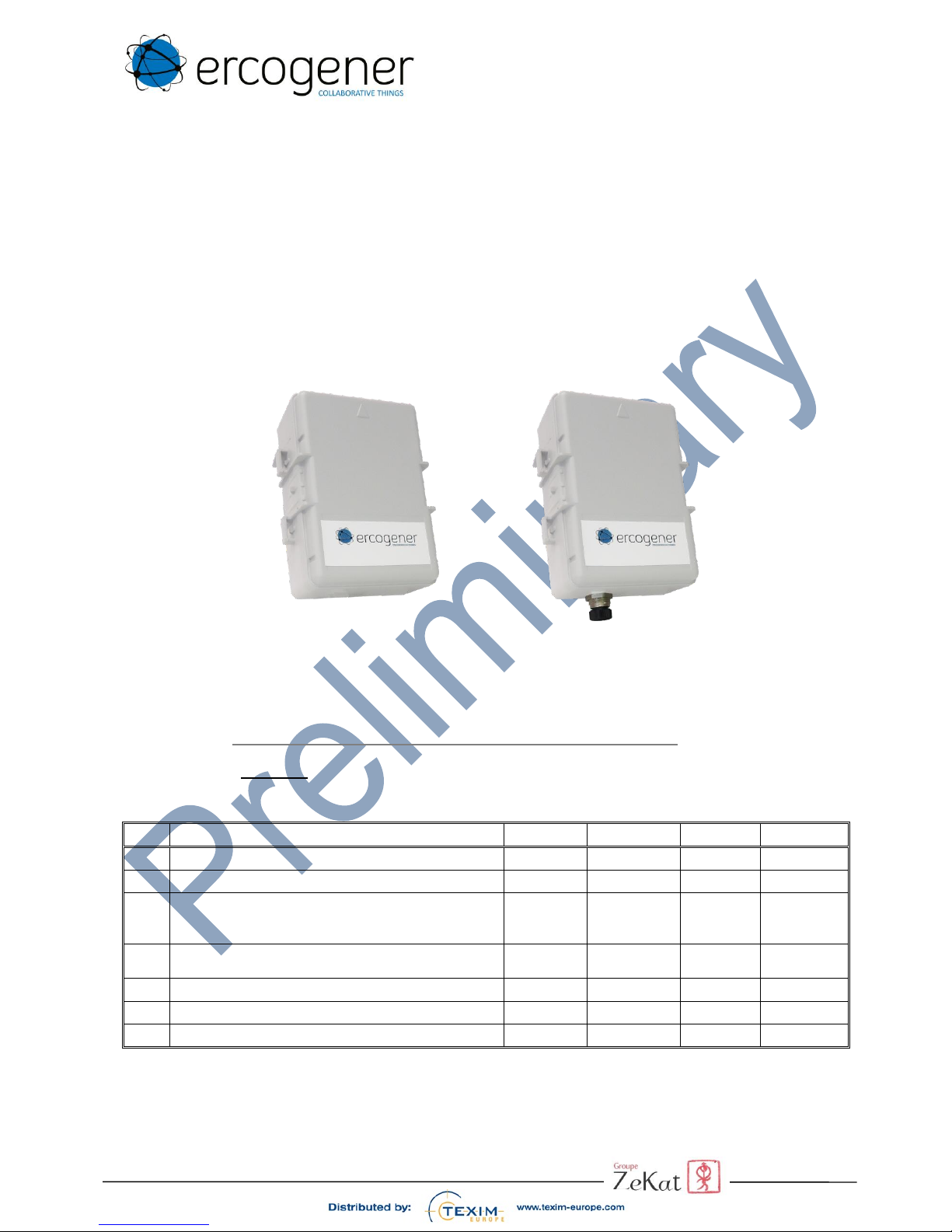
1 Presentation of the demonstrator products
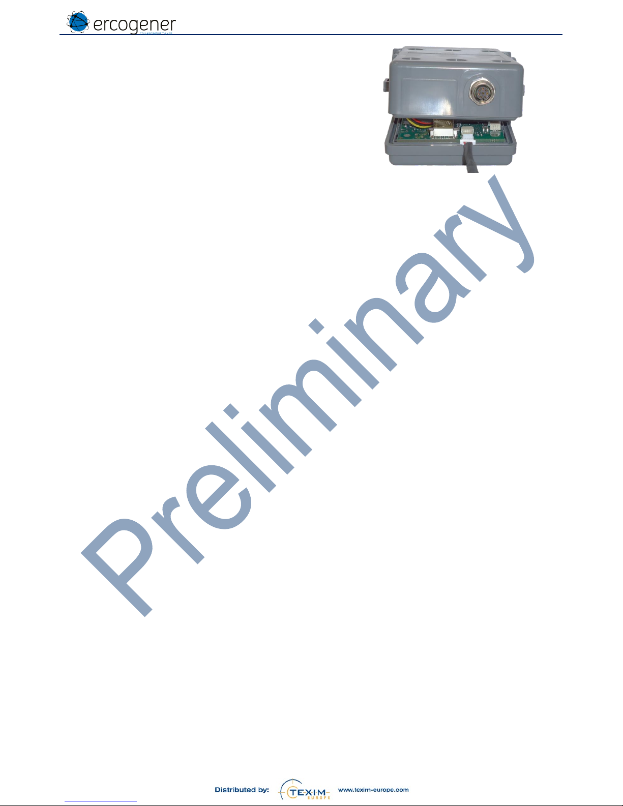
Products from the EG-IoT-xxxx family are suitable for harsh outdoor environments. They are all waterproof and
resistant to mechanical shocks.
Compact, with integrated long-range antennas and a long battery life, they are easy to implement.
The ability to have two communication technologies LPWAN+3G allows to have a product dedicated to critical
applications.
These products are intended for use in various applications such as geolocation, remote control, metering, remote
supervision …
This document presents the general characteristics and the implementation of functional demonstrators.
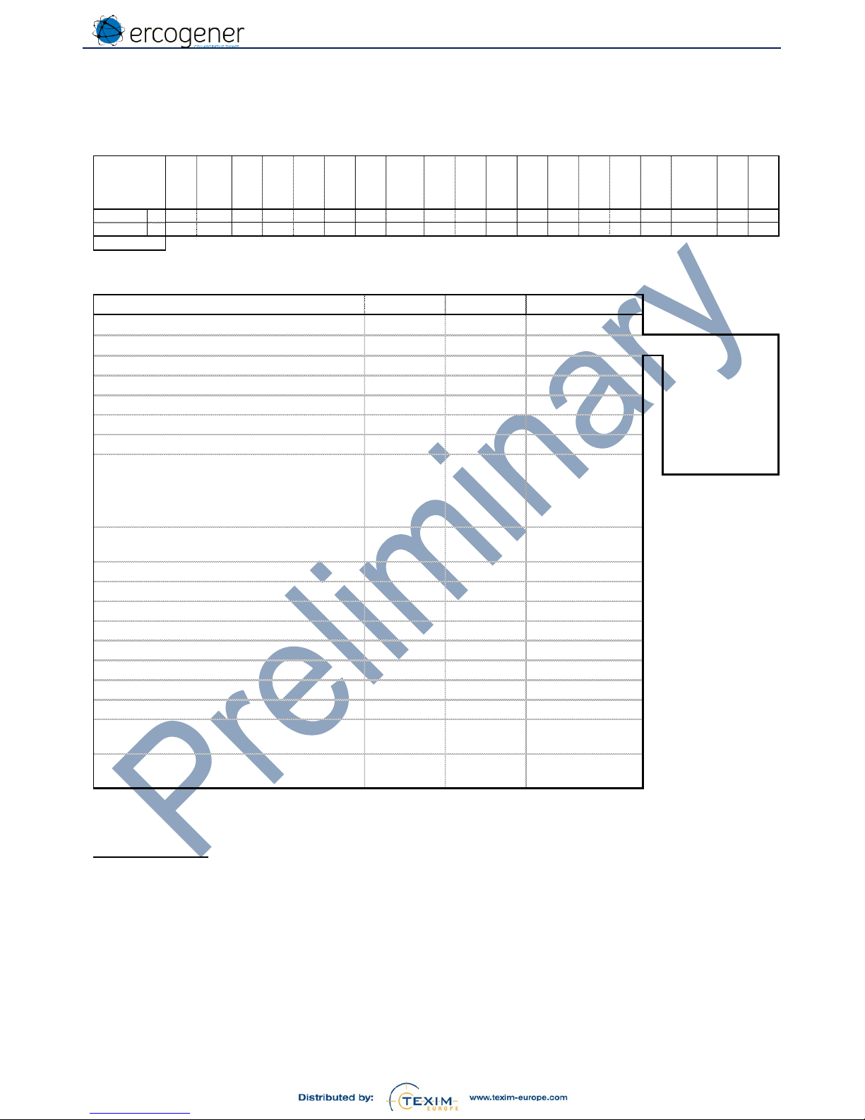
Table 1 : General Presentation
Product
LPWAN
Cellular
GNSS
BLE
M8 interface
P.supply
Input
EG-IoT
Ana.
Opto
Conta
ct
One
Wire
Out
RS485
Pwr
40B1
LoRa - - 2*-21*- - -
Battery
4281
LoRa
-
- - - - - - -
Battery
4AA6
LoRa
2G/3G
- 2 -
1*Co*1*1
Ext./Lithi
um Bat.
4AB1
LoRa
2G/3G
2*-21*- - -
Battery
4E81
LoRa
LTE Cat.M1
- - - - - - -
Battery
80B1
Sigfox
-
- 2*-21*- - -
Battery
8281
Sigfox
-
- - - - - - -
Battery
8AA6
Sigfox
2G/3G
- 2 -
1*Co*1*1
Ext./Lithi
um Bat.
8AB1
Sigfox
2G/3G
2*-21*- - -
Battery
*
Currently under development
LPWAN
Sigfox 868MHz Class 0 14dBm
BLE
BLE V4.2
LoRa 868MHz Class A 14dBm
Power supply
Ext. 8-30 VDC
Cellular
3G 800/850 900/1900 2100 MHz
Battery Li-SOCI2 3.6V – 6Ah
2G 850/900 1800/1900 MHz
Lithium Bat. 1 A.h
3.7Vdc
LTE CAT.M1 800/1800 MHz
Out
Led
GNSS
GPS / GLONASS
Co Open collector
These products are supplied with a simple demo application allowing you to make preliminary tests. As this
application is evolvable, our technical support will be able to provide its evolutions. See the paragraph
« Demonstration application » to know the restrictions of use linked with the demonstration application version.
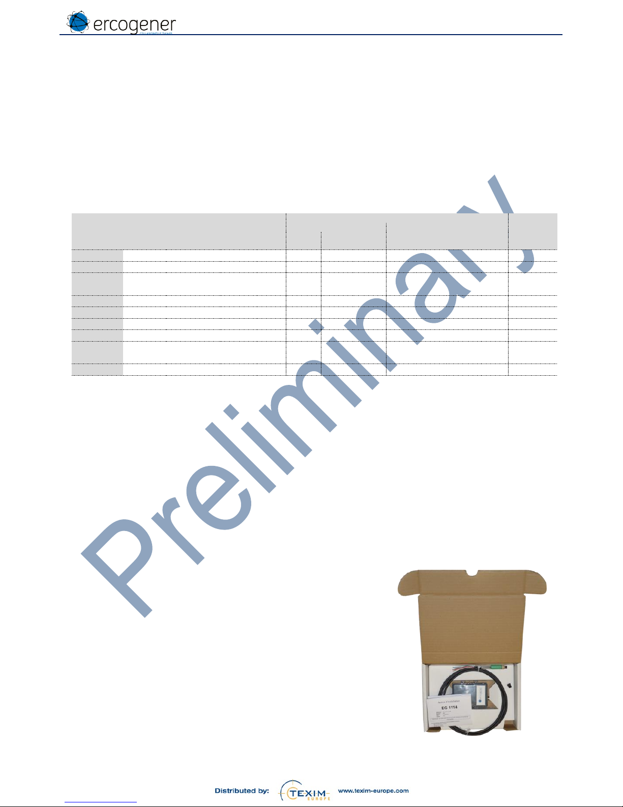
2.1 Packaging
Figure 1 : Packaging
Delivered with
A product EG-IoT - xxxx
A 8-wire cable equipped with a M8 connector (see Table 1 :
General Presentation)
A M8 sealing plug for products equipped with a M8 connector.
Installation instructions
Page 7
EG-IoT_UG_demonstrator_006_UK.docx
Page 7 / 34
Descriptions and non-contractual illustrations in this document are given as an indication only. ERCOGENER SAS reserves the right to make any
modifications. This document is the property of ERCOGENER SAS. It may not be reproduced or disclosed to a third party without the written
consent of ERCOGENER SAS.
3 Technical characteristics
3.1 General
Table 2 : General characteristics
Operating temperature
With internal battery
With external power supply and internal
lithium battery
-30°C to +75°C
-20°C to +60°C
Storage temperature
With internal battery
With external power supply and internal
lithium battery
-40 °C to +85 °C
-20°C to +35°C (+60°C max 1 month)
Dimensions
90 x 65 x 35 mm
Waterproof casing
IP67 - IP69K
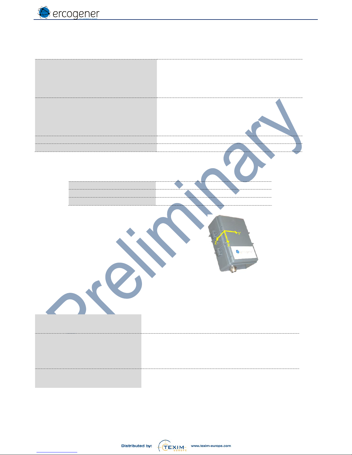
3.2 Accelerometer, Magnetometer
Table 3 : Accelerometer / Magnetometer characteristics
Specifications
Magnetic Dynamics
± 50 gauss
Accelerometer Dynamics
±2 / ±4 / ±8 / ±16 g
The X, Y and Z axes are identical for the
accelerometer and the magnetometer.
4 Operating modes
Deep sleep
The product is delivered in this mode.
Configuration / Software Update
Application configuration mode.
This is done via
The USB/TTL link with the corresponding cable
The Bluetooth link (future)
Service
The product is active according to the configuration.
Page 8
EG-IoT_UG_demonstrator_006_UK.docx
Page 8 / 34
Descriptions and non-contractual illustrations in this document are given as an indication only. ERCOGENER SAS reserves the right to make any
modifications. This document is the property of ERCOGENER SAS. It may not be reproduced or disclosed to a third party without the written
consent of ERCOGENER SAS.
5 Configuration via internal serial link
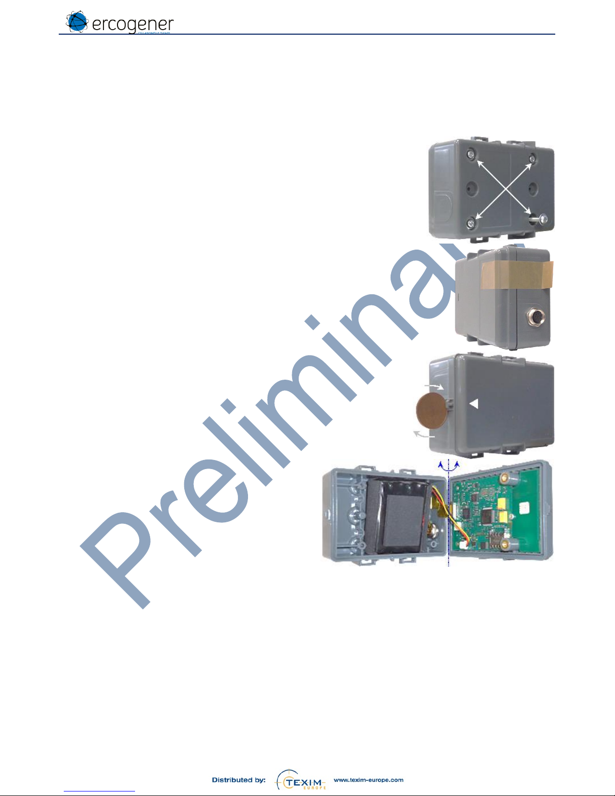
5.1 Opening the casing
Tools : Screwdriver TORX T10.
Tape
Screwdriver or coin.
1 – Using the TORX T10 screwdriver, remove the 4
screws under the casing.
2 – Optional. Stick the adhesive tape to the bottom of the
M8 connector.
3 – Use the flathead screwdriver or a coin to remove the
upper part from the lower part using the notch
provided for this purpose.
4 – Rotate the upper part, taking as the axis of rotation
the base of the casing on the M8 connector side. The
duct tape will avoid from pulling on the connections.
Page 9
EG-IoT_UG_demonstrator_006_UK.docx
Page 9 / 34
Descriptions and non-contractual illustrations in this document are given as an indication only. ERCOGENER SAS reserves the right to make any
modifications. This document is the property of ERCOGENER SAS. It may not be reproduced or disclosed to a third party without the written
consent of ERCOGENER SAS.
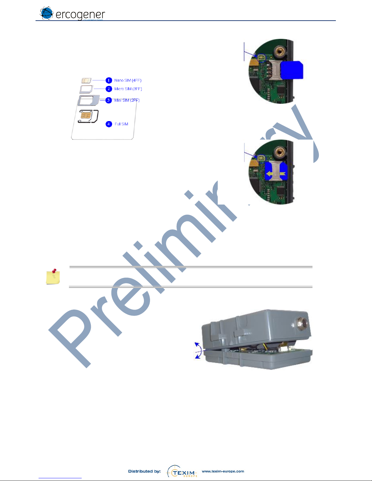
5.2 Installation of SIM card
1 – After having opened the casing (§ Erreur !
Source du renvoi introuvable. Erreur !
Source du renvoi introuvable. the casing),
Insert the Micro SIM card (format 3FF, format
N°2 on below picture).
2 – Push the Micro SIM card to the end.
5.3 Power supply connection
The product is delivered with its power supply connected. It is in deep sleep mode.
The product wakes up for a configuration:
When the converter cable USB/TTL is connected to the terminal,
At each transmission of character when the product is in sleep mode
If the power supply is disconnected, the product loses its activation capacity as its
configuration will be altered.
5.4 USB/TTL cable connection
1 – Carefully separate the upper part from the lower
part, using as the rotation axis the opposite side
of the M8 connector.
SIM card
insertion
marker
SIM card
insertion
marker
Page 10
EG-IoT_UG_demonstrator_006_UK.docx
Page 10 / 34
Descriptions and non-contractual illustrations in this document are given as an indication only. ERCOGENER SAS reserves the right to make any
modifications. This document is the property of ERCOGENER SAS. It may not be reproduced or disclosed to a third party without the written
consent of ERCOGENER SAS.
2 – Connect the 4-pin USB –TTL cable to the board
connector.
Ref. ercogener : 4440Z00025
The USB/TTL converter component is situated
inside the molded part of the cable.
Page 11

EG-IoT_UG_demonstrator_006_UK.docx
Page 11 / 34
Descriptions and non-contractual illustrations in this document are given as an indication only. ERCOGENER SAS reserves the right to make any
modifications. This document is the property of ERCOGENER SAS. It may not be reproduced or disclosed to a third party without the written
consent of ERCOGENER SAS.
5.5 Access to configuration menu
By default, the product is supplied with a demonstration application. This application allows to make tracking or to
read temperature and status of IN1 and IN2 digital inputs.
Use a Command Prompt software in order to communicate with the product.
The link between the product and the terminal is done with a USB/TTL cable: 115200,8,N,1.
Use only the USB/TTL cable recommended by ercogener (Ref. 4440Z00025).
Connect the product to the terminal.
Wait for the installation of the USB driver.
Once the driver installed, open the Device Manager to know the corresponding COM port.
Example:
Page 12

EG-IoT_UG_demonstrator_006_UK.docx
Page 12 / 34
Descriptions and non-contractual illustrations in this document are given as an indication only. ERCOGENER SAS reserves the right to make any
modifications. This document is the property of ERCOGENER SAS. It may not be reproduced or disclosed to a third party without the written
consent of ERCOGENER SAS.
Launch the terminal with the corresponding communication port.
Send the character "Carriage Return" 0D in hexa.
The following menu appears (example):
Menu with Tracking mode
Menu with Remote Reading mode
AT&D4
READY
EG1114 version [8AB1]
LPWAN: "SIGFOX", Cellular: "3G", GNSS: "GPS+GLO+GAL", BT: "BLE"
Vbat:3.599V ,Bat capacity: 0%, Tint: 26°C
__________________________________________________________
EG-IoT_DEMO - V2.03b4 - 20/11/2017 16:01:29.20
CONFIGURATION MENU:
D: Mode [0:Tracking]
1: Date ("dd/mm/yyyy") [06/12/2017]
2: Hour ("hh:mm"24H) [16:58]
3: Start activation delay (0-1440mn) [0mn]
4: Keep alive time ("I,mn";"F,[0-7],hh:mm") [I,2]
5: Alert cyclic wakeup ("HH:MM:SS") [00:10:00]
6: Transmission mode [4:Sigfox + GSM]
7: GSM/GPRS configuration IMEI [357520072362771]
SMS destination phone number []
PIN code []
APN server []
APN username []
APN password []
protocol [TCP]
TCP server []
TCP port [0]
TCP ack []
I: SIGFOX ID
A: Accelerometer [1:Enable]
F: GNSS Geofencing radius [0m]
G: GNSS Geofencing reference (lat, long) [,]
Z: Erase memory
R: Restore default values
U: Update application
S: Save
E: Exit
AT&D4
READY
EG1114 version [8AB1]
LPWAN: "SIGFOX", Cellular: "3G", GNSS: "GPS+GLO+GAL", BT: "BLE"
Vbat:3.597V ,Bat capacity: 0%, Tint: 26°C
__________________________________________________________
EG-IoT_DEMO - V2.03b4 - 20/11/2017 16:01:29.20
CONFIGURATION MENU:
D: Mode [1:Remote Reading]
1: Date ("dd/mm/yyyy") [06/12/2017]
2: Hour ("hh:mm"24H) [16:58]
3: Start activation delay (0-1440mn) [0mn]
4: Keep alive time ("I,mn";"F,[0-7],hh:mm") [I,2]
5: Alert cyclic wakeup ("HH:MM:SS") [00:10:00]
6: Transmission mode [4:Sigfox + GSM]
7: GSM/GPRS configuration IMEI [357520072362771]
SMS destination phone number []
PIN code []
APN server []
APN username []
APN password []
protocol [TCP]
TCP server []
TCP port [0]
TCP ack []
I: SIGFOX ID
N: IN1 (Type, Rest state, Value, Threshold) [0,0,0,65535]
O: IN2 (Type, Rest state, Value, Threshold) [0,0,0,65535]
?: Read inputs state
T: Temperature threshold (Low, High) [-30°C,60°C]
Z: Erase memory
R: Restore default values
U: Update application
S: Save
E: Exit
For more details, see the paragraph «Demonstration Application».
Page 13

EG-IoT_UG_demonstrator_006_UK.docx
Page 13 / 34
Descriptions and non-contractual illustrations in this document are given as an indication only. ERCOGENER SAS reserves the right to make any
modifications. This document is the property of ERCOGENER SAS. It may not be reproduced or disclosed to a third party without the written
consent of ERCOGENER SAS.
This menu allows to set:
The operating mode
The date and then the time (this order must be respected)
The timeout before its activation
The period of transmission of the Keep Alive frame
The period of transmission of frames in alert mode
The kind of transmission activated
The identifiers and the transmission modes depending on the communication technology available on the
product
o For cellular : the IMEI number is the one of the EG-IoT internal module
o For Sigfox, the Sigfox ID and the PACID can be read with the configuration application when
entering the character « i ».
o For LoRa (use of OTAA connections) :
The DevEUI (8 digits : HWEUI of the embedded module)
The AppEUI (8 digits : 6572636F67656E65)
The AppKEY (16 digits : 4552434F47454E45522D454731313134).
These keys can be modified in the configuration menu.
For the tracking mode
o The geofencing circular zone
o The reference position
For the mode telemetering / pulse counting / Hour meter
o The alert thresholds for high and low temperature
o The modes of use of each digital input :
Pulse counting
Hour meter
Detection of status change
o Alert threshold on each digital input
o The initialization value of meters
Page 14

EG-IoT_UG_demonstrator_006_UK.docx
Page 14 / 34
Descriptions and non-contractual illustrations in this document are given as an indication only. ERCOGENER SAS reserves the right to make any
modifications. This document is the property of ERCOGENER SAS. It may not be reproduced or disclosed to a third party without the written
consent of ERCOGENER SAS.
The character has to be entered at the beginning of the line in order to activate the corresponding setting: enter 1 to
modify the date for example, and follow the instructions.
Example of display
Observation
D: Mode [0:Tracking]
Transmission mode [0]:
0: Tracking
1: Remote Reading
The menu will adapt depending on the selected
mode.
1: Date ("dd/mm/yyyy") [01/01/2000]
Date ("dd/mm/yyyy") [01/01/2000]
Réglage date
2: Hour ("hh:mm"24H) [00:00]
Time ("hh:mm" 24H) [00:00]:
Time setting
3: Start activation delay (0-1440mn) [0mn]
Start activation delay (0-1440mn,0: not
actived ): "0mn"
Activation timeout
4: Keep alive time ("I,mn";"F,[0-7],hh:mm") [I,480]
("I,mm";"F,[0-7],hh:mm")
Example :"I,1440" => Interval Time keep
alive every 1440mn [1-1440mn]
Example :"F,0,12:00" => Fix Time keep
alive everyday at 12:00
Example :"F,2,23:59" => Fix Time keep
alive every Tuesday at 23:59
Example :"F,7,01:00" => Fix Time keep
alive every Sunday at 01:00
[I,480]:
Timeout for transmission of regular frame
5: Alert cyclic wakeup ("HH:MM:SS") [00:10:00]
Cyclic wakeup ("HH:MM:SS") [00:10:00]:
Cyclical alert
6: Transmission mode [0:GSM/GPRS]
Transmission mode [0]:
0: GSM/GPRS
1: LoRa
2: Sigfox
3: LoRa + GSM/GPRS backup
4: Sigfox + GSM/GPRS
GSM/GPRS Mode requires SIM card
The menu will adapt depending on the
transmission modes selected
7: GSM/GPRS configuration IMEI [xxxxxxxxxxxxxxx]
Access to parameters below.
SMS destination phone number []
SMS destination phone number: ""
Enter phone number:
PIN code []
PIN Code: ""
Enter PIN Code (if requested):
APN server []
APN server: ""
Enter APN server:
APN username []
APN username: ""
Enter APN username:
APN password []
APN password: ""
Enter APN password:
protocol [TCP]
Transfert protocol: "UDP"
Enter protocol "T":TCP, "U":UDP
TCP server []
TCP server: ""
Enter TCP server:
TCP port [0]
TCP port: "0"
Enter TCP port:
TCP ack []
TCP ack: ""
Enter returns acknowledge string:
I: SIGFOX ID
$I0-FRW: "AX-Sigfox 1.1.0-ETSI"
$I2-HWL: "8F"
$I3-HWH: "51"
$I4-FWH: "1"
$I5-FWL: "1"
$I7-VAR: "ETSI"
$I8-VCS: "0"
$I9-LIB: "UDL1-1.8.7"
$I10-ID : "00192F6E"
$I11-PAC: "4DEDEAFA03481A22"
A: Accelerometer [1:Enable]
A: Accelerometer (0:Disable , 1:Enable):
"1:Enable"
N: IN1 (Type, Rest state, Value, Threshold) [0,0,0,65535]
IN1
(Type, Rest state, Value, Threshold)
Page 15

EG-IoT_UG_demonstrator_006_UK.docx
Page 15 / 34
Descriptions and non-contractual illustrations in this document are given as an indication only. ERCOGENER SAS reserves the right to make any
modifications. This document is the property of ERCOGENER SAS. It may not be reproduced or disclosed to a third party without the written
consent of ERCOGENER SAS.
Type : 0=Disable / 1=Pulse Counter /
2=Minutes Meter / 3=Edge Detection
Rest state : 0=Low / 1=High
[0,0,0,65535]:
F: GNSS Geofencing radius [0m]
GNSS Geofencing Radius (0: not actived ):
"0m"
O: IN2 (Type, Rest state, Value, Threshold) [0,0,0,65535]
IN2
(Type, Rest state, Value, Threshold)
Type : 0=Disable / 1=Pulse Counter /
2=Minutes Meter / 3=Edge Detection
Rest state : 0=Low / 1=High
[0,0,0,65535]:
G: GNSS Geofencing reference (lat, long) [,]
GNSS Geofencing reference (lat, long):
"0.00000,0.00000"
?: Read inputs state
IN1: 0,IN2: 0
Z: Erase memory
Do you want to erase memory ? (Y-N)
T: Temperature threshold (Low, High) [-30°C,60°C]
Temperature threshold (Low, High) in °C
(To disable thresholds events : Low = 30°C, High = 60°C)
[-30,60]:
R: Restore default values
Do you want to restore default values ?
(Y-N)
U: Update application
Are you sure to enter in Bootloader mode ?
(Y-N)
S: Save
Config saved
E: Exit
Exit menu
If the application does not receive any character after a timeout of 2 mn, the product goes
back to deep sleep mode.
To wake it up, a new character has to be entered.
Each wakeup of the application means a reset, so consequently, the actions programed
during this status change are processed (Restart of start activation).
Once the configuration is done, enter 'S' to save the parameters. The activation of the product
will be active after the timeout defined in line 3 of the menu 'Start activation delay
(0-1440mn)'.
If you enter 'U' to update the application, you enter in bootloader mode. The application is not
available anymore and the product is waiting for a new application without going back to a
deep-sleep mode.
The power supply must be disconnected and reconnected in order to go back to the
configuration menu if the update is not done immediately.
Page 16

EG-IoT_UG_demonstrator_006_UK.docx
Page 16 / 34
Descriptions and non-contractual illustrations in this document are given as an indication only. ERCOGENER SAS reserves the right to make any
modifications. This document is the property of ERCOGENER SAS. It may not be reproduced or disclosed to a third party without the written
consent of ERCOGENER SAS.
5.6 Update of embedded software via Boot loader
For this, you must have the application STM32 Flash Loader.exe with its dll : STBootLib.dll
You also must have the new (latest) application to be installed: EG-IoT_Traceur_Vx.xx.bin (example)
Start the program STM32 Flash Loader.exe
1) The following window appears:
Select the port corresponding to
the cable
2) Select the port speed, other than
115 200 bauds:
3) Select the file
Select a port speed other than 115 200 bauds.
The software is ready to load the new application.
From the configuration menu
Enter Z and then Y (strongly advised)
Enter U and then Y
z
Do you want to erase memory ? (Y-N)
y
In progress...
…
…
u
Are you sure to enter in Bootloader mode ? (Y-N)
y
Bootloader waiting for STM32 Flash Loader...
Close the COM port currently used
Page 17

EG-IoT_UG_demonstrator_006_UK.docx
Page 17 / 34
Descriptions and non-contractual illustrations in this document are given as an indication only. ERCOGENER SAS reserves the right to make any
modifications. This document is the property of ERCOGENER SAS. It may not be reproduced or disclosed to a third party without the written
consent of ERCOGENER SAS.
In the window of the STM32 Flash Loader, select « Write Firmware & Jump »
The message » Erasing » appears
The message « Programming »
appears
The message « Success » appears
The new software version is automatically launched.
To check it, open the COM port with the terminal software and from the menu, enter « V ».
In case the menu does not appear, disconnect the battery, wait a few seconds and reconnect it.
Page 18

EG-IoT_UG_demonstrator_006_UK.docx
Page 18 / 34
Descriptions and non-contractual illustrations in this document are given as an indication only. ERCOGENER SAS reserves the right to make any
modifications. This document is the property of ERCOGENER SAS. It may not be reproduced or disclosed to a third party without the written
consent of ERCOGENER SAS.
5.7 Closing the casing
1 – Connect the Lexan in case it has been disconnected
A – Carefully unlock the connector.
B – Insert the Lexan.
C – Carefully lock the connector.
2 – Connect the battery or the lithium battery in
case it has been disconnected.
A – Check the presence of the SIM card.
B – Connect the battery or the lithium
battery.
3 – While placing the battery or the lithium battery,
check that the Lexan is not folded.
4 – After having installed the battery or the lithium
battery, check that the wires are positioned
according to this picture.
5 – Close the housing. Check the presence of the
seal on the 4 screws to ensure the
waterproofness.
6 – With the TORX T10 screwdriver, place the 4
screws under the housing.
Once the screws stop, make an additional
quarter turn to ensure the waterproofness.
Page 19
EG-IoT_UG_demonstrator_006_UK.docx
Page 19 / 34
Descriptions and non-contractual illustrations in this document are given as an indication only. ERCOGENER SAS reserves the right to make any
modifications. This document is the property of ERCOGENER SAS. It may not be reproduced or disclosed to a third party without the written
consent of ERCOGENER SAS.
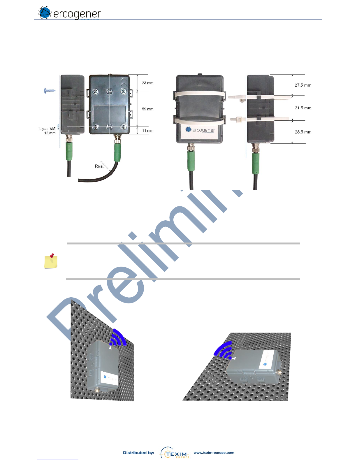
5.8 Fixing
5.8.1 Standard
With 2 screws
Self-drilling for thermoplastic
Ø 3 mm x Lg
MAX.
: 12 mm
With 2 Polyamide tie raps
Length
MIN.
: 230 mm
Width
MAX
. : 7 mm
Minimum bending radius of the cable
Fix position R
MIN
. = 25,5 mm
Flexible position R
MIN.
= 51 mm
5.8.2 Installation
For optimum conditions of transmission and reception
The arrow must be positioned upwards (see figure below)
Avoid any obstacle on and in front of the product.
If the M8 cable is not connected, the cap must be placed on the connector of the
product in order to ensure its waterproofness
Figure 2 : Installation / Position
Page 20

EG-IoT_UG_demonstrator_006_UK.docx
Page 20 / 34
Descriptions and non-contractual illustrations in this document are given as an indication only. ERCOGENER SAS reserves the right to make any
modifications. This document is the property of ERCOGENER SAS. It may not be reproduced or disclosed to a third party without the written
consent of ERCOGENER SAS.
6 Demonstration application:
This application will allow you to test the product for different cases of use.
This application will have evolutions and in this case, updates will be communicated.
1114_DEMO_V1.00
Tracking only, LoRa, Sigfox, SMS
1114_DEMO_V2.00
Addition telemetering/counting/hour meter (IN1, IN2, T°C), LoRa, Sigfox,
SMS
1114_DEMO_V2.01
Addition management of TCP protocol TCP in 3G
1114_DEMO_V2.03b4
Optimization of LoRa driver, addition UDP, addition LTE CAT.M1
management, addition estimation of battery remaining capacity
Not available yet
datalogger, ANA inputs management, magnetometer, BLE, RS485, 1W
6.1.1 Principle
This version of demonstration is unidirectional for the transmission of information to a server and the SMS
transmission.
The features taken into account are:
Management of internal serial port for configuration
Management of date and time
Management of timeout between the configuration and the activation
Management of keepalive frame
Management of ways of transmission : LoRa, Sigfox, 2G/3G, LTE CAT.M1 for transmission of SMS and/or
TCP/UDP frame
Management of internal temperature reading
For tracking
o Management of position report
o Management of entry/exit of a circular zone
o Management of movement detection
o Management of alert upon entry/exit of a zone
o Management of alert upon start of movement and stop of movement
o Management of cyclical transmission of frame during movement
For telemetering
o Management of the 2 digital inputs
o Management of pulse counting on each of the 2 inputs
o Management of hour meter on each of the 2 inputs
o Management of thresholds for counting (high level) and temperature (low level and high level)
o Management of alert upon status change of an input (upwards or downwards from the normal level
of reference)
The main limits of this application are visible in the configuration menu of each parameter. The fixed limits not
indicated in the menu are :
The time is a UTC time
Hysteresis of zone entry/exit (geofencing) : 50m
Hysteresis around temperature threshold : 2°C
Resolution of pulse counting : F
max
=20Hz, Ton mini=12ms
Resolution of hour meter : duration mini 1s, resolution 1mn, duration max 65535mn, corresponding to 45
days
Detection of movement (vehicle transport mode) : start of movement constant during 2s, stop of movement
after 3 mn of immobilization
LPWAN networks coverage:
o Sigfox : https://www.sigfox.com/en/coverage
o LoRa Objenius : http://objenious.com/reseau/
o LoRa LiveObject : not communicated
To save power, the product wakes up:
At the Keep alive frequency or at the alert cyclical frequency
Upon an asynchronous event: movement or front detection
There is no asynchronous event for the temperature threshold overrun. The first alert is sent depending on
the keep alive frequency.
Page 21

EG-IoT_UG_demonstrator_006_UK.docx
Page 21 / 34
Descriptions and non-contractual illustrations in this document are given as an indication only. ERCOGENER SAS reserves the right to make any
modifications. This document is the property of ERCOGENER SAS. It may not be reproduced or disclosed to a third party without the written
consent of ERCOGENER SAS.
6.1.2 Application in tracking mode:
6.1.2.1 Operating chronogram and kind of frame
The application is able to send several kinds of frame, each frame has an identifier called Opcode.
The first frame of activation:
o Opcode 0X00 in tracking mode
o It is sent to indicate that the activation is functional.
o It is sent after the timeout set at line 3 of the configuration menu 'Start activation delay'
Example of chronogram
configuration
Start activation delay
0x00
time
The cyclical frame of KeepAlive (Opcode 0x11)
o It is cyclically sent according to the parameters set at line 4 of the configuration menu 'Keep alive time'.
0x00
Keep alive time
0x11
Keep alive time
0x11
time
A frame of alert is sent if the product detects a start of movement (Opcode 0x84), then the product cyclically
sends a movement frame (Opcode 0x10) set at line 5 of the configuration menu 'Alert cyclic wakeup' until the
end of movement is detected (Opcode 0x80)
Alert cyclic wakeup
Alert cyclic wakeup
0x11 0x84
0x10
0x10
0x10
0x80
0x11
time
During the movement detection, an alert frame of zone exit (Opcode 0xA0) will be sent, as well as a zone
entry frame (Opcode 0xC0) if the geofencing is activated on the configuration.
Alert cyclic wakeup
Alert cyclic wakeup
0x84
0x10
0xA0
0x10
0x10
0xC0
0x10 0x80
time
The entry and exit of zone are the priority for the movement detection. The opcode of end of movement does
not appear if it is present with an entry or exit of zone.
Alert cyclic wakeup
Alert cyclic wakeup
0x11 0x84
0x10
0x10
0x10
0xA0
0x11 time
Alert cyclic wakeup
Alert cyclic wakeup
0x11 0x84
0x10
0xA0
0x10
0xC0
0x11 time
Page 22
EG-IoT_UG_demonstrator_006_UK.docx
Page 22 / 34
Descriptions and non-contractual illustrations in this document are given as an indication only. ERCOGENER SAS reserves the right to make any
modifications. This document is the property of ERCOGENER SAS. It may not be reproduced or disclosed to a third party without the written
consent of ERCOGENER SAS.
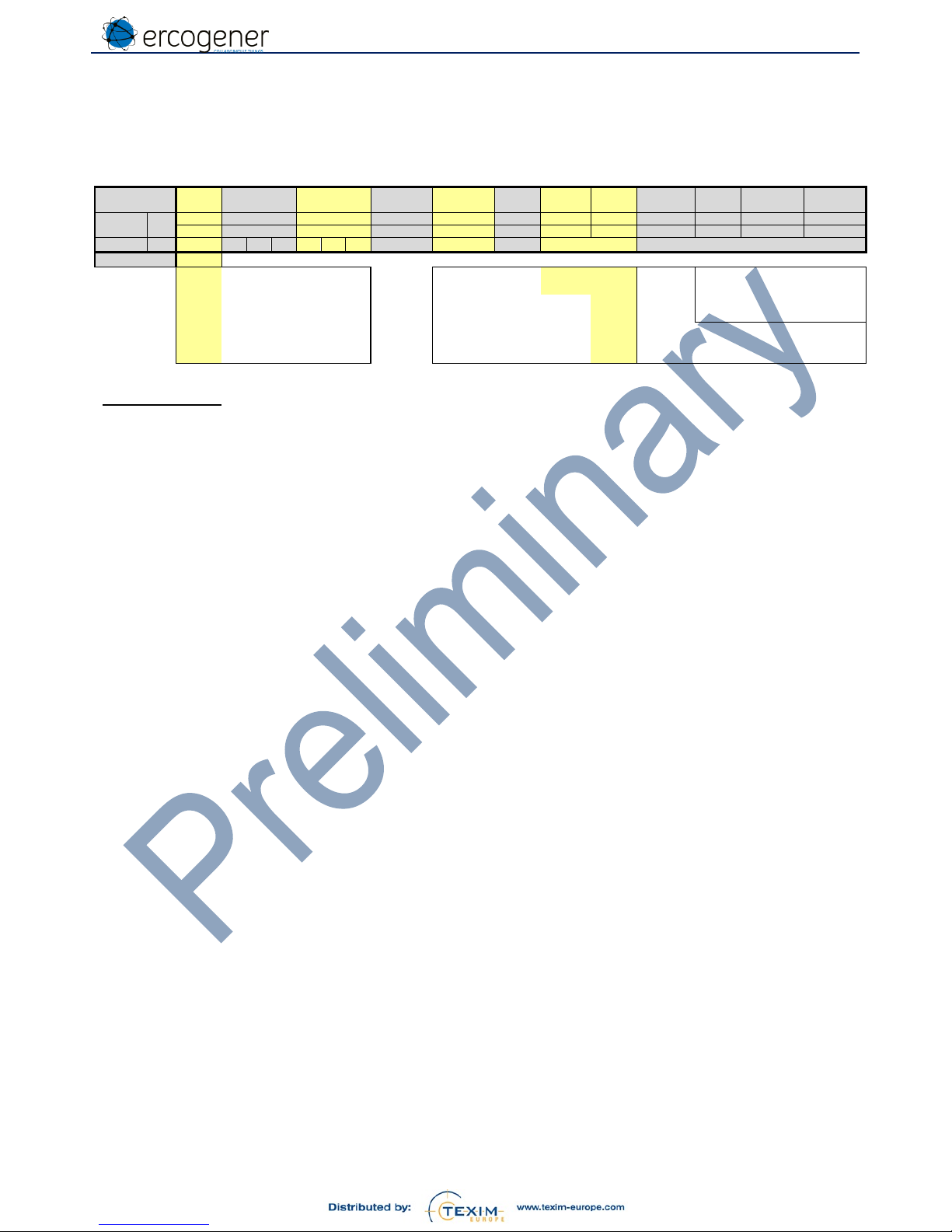
6.1.2.2 Payload for Sigfox network or LoRa network
The payloads sent by the product have only one format for the tracking. Only the Opcode allows the identification of
the kind of frame.
Op
Code
Latitude
Longitude
Reserved
Reserved
V
BAT
GNSS
Fix
T° int.
Speed
10 km/h
HDOP
Reserved
Reserved
Bit
96
8
24
24 8 8 8 1 7 4 2 1 1 b7-b0
b23-b0
b23-b0
b7-b0
b7-b0
b7-b0
b7
b6-b0
b7-b4
b3-b2
b1
b0
Octet
12
0
1 2 3 4 5 6 7 8 9
10
11
Value
xx
00
Service init.
Invalid measure
0
00
0<2 Very good
10
Cyclical frame
Valid measure
1
01
2<5 Good
11
Life frame of EG-IoT
10
5<9 Moderate
80
End of movement > 85 °C
0x7F 11
9<20 Poor
84
Movement detection 85 °C
0x7E
A0
Exit zone
0 °C
0x28
0000
Speed
C0
Entry zone
-40 °C
0x00
FFFF
10 Km/h par bit
Example of frame:
Opcode: Cyclic, Lat: 47.211467, Long: -0.060360, Vbat: 3.30V, GNSS Fix: Valid, T°int: 40°C, Speed: 35.2km/h, HDOP: 1.75
Frame : (all values in hexadecimal)
Opcode .............. : Cyclic 10
Lat ...................... : 47.211467 x 10000 = 472115 0x073433
Long ................... : -0.060360 x 10000 = -604 0xFFFDA4
Reserved 1 & 2 .. : 00 00
V
BAT
.................... : 3.30V (3.30 x 100) – 200 = 130 0x82 (Note : measure range 2.00V à 4.55V)
GNSS Fix ........... : Valid measure 1
T° int ................... : 40°C = 0x28, 0x28 + 0x28 (0°) 0x50 (Note : measure range -40°C à 85°C)
Speed ................. : 35.2 km/h 0x0011
HDOP ................. : 1.75 very good 00
Reserved ............ : 0 0 0 0
Frame in octets ............... : 0x10 0x07 0x34 0x33 0xFF 0xFD 0xA4 0x00 0x00 0x82 0xD1 0x30
Conversion in ASCII ....... : 10073433FFFDA4000082D130 Payload Sigfox/LoRa
Page 23
EG-IoT_UG_demonstrator_006_UK.docx
Page 23 / 34
Descriptions and non-contractual illustrations in this document are given as an indication only. ERCOGENER SAS reserves the right to make any
modifications. This document is the property of ERCOGENER SAS. It may not be reproduced or disclosed to a third party without the written
consent of ERCOGENER SAS.
6.1.2.3 Frame sent by SMS
The transmission of information by SMS indicates the IMEI of the product, the OpCode, the date and time and
additional useful information. The link at the end of the SMS allows the location of the product directly on Google
Maps ©.
Do not take into account the comma (,) as a separator in the Google Maps link
https://www.google.fr/maps/place/47.211467,-0.060360
Example of frame:
ID : 1234564798012345
Opcode:01(Cyclic), Date: 250717, Time: 123456, Lat: 47.211467, Long: -0.060360, Speed: 35.2km/h, GNSS Fix:
Valid, HDOP : 1.75, Vbat: 3.531V, T°int: 27°C, Remaining bat: 53%
The 2nd SMS below represents the same frame without valid GPS position.
SMS
1234564798012345,10,250717,123456,47.211467,-
0.060360,35.2,1,1.75,0,0,3531,27,0,0,53,"https://www.google.fr/maps/place/47.211467,-0.060360"
1234564798012345,10,,,,,,0,99.99,0,0,3531,27,0,0,53,"https://www.google.com/maps/place/0.000000,0.000000"
SMS IMEI/ID Opcode DATE TIME LAT LONG Speed
GNSS
Fix status
HDOP res.* res.* Vbat T° int res.* res.*
Remaining
bat
Google Maps link
to see the position
Characters 136 15 2 6 6 10 11 5 1 5 5 5 4 5 1 1 2 52
Separators (,) 16 1 1 1 1 1 1 1 1 1 1 1 1 1 1 1 1 0
Total chars 152
res.* :
reserved
SMS Min Max Exemple
GSM IMEI / custom ID 0 chars 15 chars 123456789012345
Opcode (Hexa decimal) 00 C0 10
00 = init
DATE (ddmmyy) 000000 311299 200717
10 = cyclic
TIME (hhmmss) 000000 235959 093653
11 = Keep alive
LAT (Decimal degrees) -89.999999 89.999999 47.211467
84 = Movement start
LONG (Decimal degrees) -179.999999 179.999999 -0.060360
80 = Movement stop
Speed (km/h) 0.0 999.9 35.2
A0 = Exit zone 0
GNSS Fix status : -1 : Unavailable -1 2 1
C0 = Entry zone 0
0 : Invalid
1 : GPS Fix (2D/3D)
2 : DGPS Fix
HDOP
Horizontal Dilution of Precision (<2 good value)
0.00 99.99 2.34
reserved 0 0 0
reserved 0 0 0
Vbat (mV) 0 9999 3300
Tint (°C) -40.0 85.0 25.3
reserved 0 0 0
reserved 0 0 0
Remaining bat capacity (%) 0 99 53
Google Maps link to see the position 0 52 https://www.google.fr/maps/place/47.211467,-0.060360
Page 24
EG-IoT_UG_demonstrator_006_UK.docx
Page 24 / 34
Descriptions and non-contractual illustrations in this document are given as an indication only. ERCOGENER SAS reserves the right to make any
modifications. This document is the property of ERCOGENER SAS. It may not be reproduced or disclosed to a third party without the written
consent of ERCOGENER SAS.
6.1.2.4 Frame sent via TCP or UDP
The transmission of information by SMS indicates the IMEI of the product, the OpCode, the date and time and
additional useful information.
* voir ANNEX 3 – GSM (RSSI/QUAL) LTE (RSRQ/RSRP)
Example of frame:
ID : 1234564798012345
Opcode:01(Cyclic), Date: 250717, Time: 123456, Lat: 47.211467, Long: -0.060360, Speed: 35.2km/h, GNSS Fix: Valid,
HDOP : 1.75, Vbat: 3.30V, T°int: 40°C, Remaining bat: 53%, Altitude:60.4m, RSSI=10, QUAL=10
FRAME
1234564798012345,10,250717,123456,47.211467,-0.060360,35.2, 1, 1.75 ,0,0,3300,40,0,0,60.4,53,10,10
IMEI/ID Opcode DATE TIME LAT LONG Speed
GNSS Fix
status
HDOP res.* res.* Vbat T° int res.* res.* Altitude
Remaining
bat
GSM
RSSI
GSM
QUAL
Characters 96 15 2 6 6 10 11 5 1 5 5 5 4 5 1 1 6 2 3 3
Separators (,) 18 1 1 1 1 1 1 1 1 1 1 1 1 1 1 1 1 1 1 0
Total chars 114
res.* :
reserved
TCP/UDP
TCP/UDP Min Max Exemple
GSM IMEI/custom ID 0 chars 15 chars 123456789012345
Opcode (Hexa decimal) 00 C0 10
00 = init
DATE (ddmmyy) 000000 311299 200717
10 = cyclic
TIME (hhmmss) 000000 235959 093653
11 = Keep alive
LAT (Decimal degrees) -89.999999 89.999999 47.211467
84 = Movement start
LONG (Decimal degrees) -179.999999 179.999999 -0.06036
80 = Movement stop
Speed (km/h) 0 999.9 35.2
A0 = Exit zone 0
GNSS Fix status : -1 : Unavailable -1 2 1
C0 = Entry zone 0
0 : Invalid
1 : GPS Fix (2D/3D)
2 : DGPS Fix
HDOP
Horizontal Dilution of Precision (<2 good value)
0 99.99 2.34
reserved
0 0 0
reserved
0 0 0
Vbat (mV)
0 9999 3300
Tint (°C)
-40 85 25.3
reserved
0 0 0
reserved
0 0 0
Altitude (m) -12000 12000 40.3
Remaining bat capacity % 0 99 53
GSM RSSI level*
or RSRQ (for LTE)*
0
0
31 ou 99
34 ou 255
10
GSM QUAL*
or RSRP (for LTE)*
0
0
7 ou 99
97 ou 255
10
Page 25

EG-IoT_UG_demonstrator_006_UK.docx
Page 25 / 34
Descriptions and non-contractual illustrations in this document are given as an indication only. ERCOGENER SAS reserves the right to make any
modifications. This document is the property of ERCOGENER SAS. It may not be reproduced or disclosed to a third party without the written
consent of ERCOGENER SAS.
6.1.3 Application with mode telemetering / pulse counting / Hour meter:
6.1.3.1 Operating chronograms and kind of frames
The first frame of activation:
o Opcode 0XFE with mode telemetering/pulse counting/hour meter
o It is sent to indicate that the activation is operational.
o It is sent after the timeout set at line 3 of the configuration menu
Example of chronogram
configuration
Start activation delay
0xFE time
The KeepAlive cyclical frame (Opcode 0x11)
o It is cyclically sent according to parameters set at line 4 of the configuration menu
0xFE
Keep alive time
0x11
Keep alive time
0x11
time
An alert frame is sent if the threshold is reached (Opcode 0x17). For temperature threshold overrun, the
frequency of frames transmission depends on the configuration at line '5' menu 'Alert cyclic wakeup'.
Alert cyclic wakeup
Alert cyclic wakeup
0x11
0x17
0x17
0x17
0x17
0x17
0x11
time
6.1.3.2 Functioning of inputs
The inputs initialization is defined by 4 parameters IN (Type, Rest state, Value, Threshold)
Type : 0=Disable
1=Pulse Counter
2=Minutes Meter
3=Edge Detection
Rest state : 0=Low Status of input in idle mode
1=High
Value Initialization of counter if necessary.
Threshold alarm threshold for hour meter or counting.
Page 26

EG-IoT_UG_demonstrator_006_UK.docx
Page 26 / 34
Descriptions and non-contractual illustrations in this document are given as an indication only. ERCOGENER SAS reserves the right to make any
modifications. This document is the property of ERCOGENER SAS. It may not be reproduced or disclosed to a third party without the written
consent of ERCOGENER SAS.
6.1.3.3 Counting
Counting on upwards front
Counting on downwards front
≥12ms
≥12ms
≥ 50 ms
≥ 50 ms
Rest state = 0 / Low
Rest state = 1 / High
Ex :
1,0,125,0
Initialization of counter at 125, no alarm
Ex:
1,1,0,100
Alarm when the counter reaches 100
The alarm frame OpCode 17 is sent at the end of the Keep Alive Time.
6.1.3.4 Hour meter
Hour meter at high level
Hour meter at low level
Rest state = 0 / Low
Rest state = 1 / High
Ex :
2,0,0,0
Ex:
2,1,0,60
Alarm when the time reaches 60 mn.
The alarm frame OpCode 17 is sent at the end of the Keep Alive Time.
6.1.3.5 Front detection
Alarm on upwards front
Alarm on downwards front
60ms
60ms
Rest state = 0 / Low
Rest state = 1 / High
Ex :
3,0,0,0
Ex:
3,1,0,0
The alarm frame OpCode 17 is sent 60 ms after the change of status is taken into account.
Page 27

EG-IoT_UG_demonstrator_006_UK.docx
Page 27 / 34
Descriptions and non-contractual illustrations in this document are given as an indication only. ERCOGENER SAS reserves the right to make any
modifications. This document is the property of ERCOGENER SAS. It may not be reproduced or disclosed to a third party without the written
consent of ERCOGENER SAS.
6.1.3.6 Payload for Sigfox or LoRa
PayLoad
Op
Code
Compt.
1
Compt.
2
Res.
Res.
Res.
V
BAT
-
Temp.
°C
Status of inputs / Alarms
Bits
88
8
16
16 8 8 8 8
8
8
b7-b0
B15-b0
B15-b0
b7-b0
b7-b0
b7-b0
b7-b0
b7
B6-b0
b7
b6
b5
b4
b3
b2
b1
b0
Octet
11
0 1 2 3 4 5 6 7 8
9
10
Value
0x--
reserved
-
Status input 1
b0
11
Life frame of EG-IoT
17
Alarm frame
> +86 °C
0x7F
Status input 2
b1
FE
Service Init.
+86 °C
0x7E
0 °C
0x28
Counter 1 < Threshold
0
-40 °C
0x00
Counter 1 ≥ Threshold
1
Counter 2 < Threshold
0
Counter 2 ≥ Threshold
1
Tmp. °C > Low threshold
0
Tmp. °C ≤ Low threshold
1
Tmp. °C ≥ High
threshold
0
Tmp. °C < High
threshold
1
Compt.
Counter
Res.
Reserved
Reserved
b7
b6
Example of frame:
Opcode: Keep alive, Digital input 1 counter : 100 , Digital input 2 counter : 32, Vbat: 3.30V, T°int: 40°C
Frame : (all values in hexadecimal)
Opcode ........................ : Keep alive 11
Digital input 1 counter .. : 100 0x0064
Digital input 2 counter .. : 32 0x0020
Reserved 1 & 2 ............ : 0x00 0x00
Vbat .............................. : 3.30V (3.30 x 100) – 200 = 130 0x82 (Note : measure range 2.00V à 4.55V)
T°int .............................. : 40°C = 0x28, 0x28 + 0x29 (0°) 0x51 (Note : measure range -40°C à 85°C)
Digital status ................ : none 0x00
Frame in octets ............ : 0x11 0x00 0x64 0x00 0x20 0x00 0x00 0x82 0x51 0x00
Conversion in ASCII .... : 1100640020000000825100 Payload Sigfox/LoRa
Page 28

EG-IoT_UG_demonstrator_006_UK.docx
Page 28 / 34
Descriptions and non-contractual illustrations in this document are given as an indication only. ERCOGENER SAS reserves the right to make any
modifications. This document is the property of ERCOGENER SAS. It may not be reproduced or disclosed to a third party without the written
consent of ERCOGENER SAS.
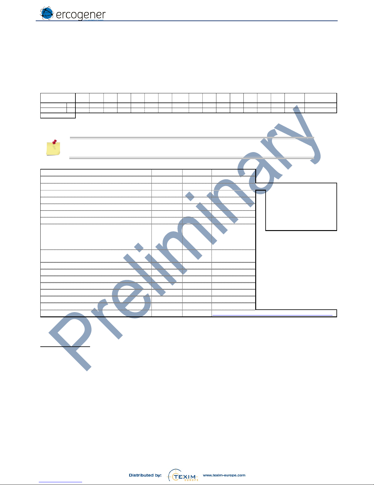
6.1.3.7 Frame sent via SMS
SMS
Unit
Nb car
min.
Nb car
max.
Value
min.
Value
max.
Example
GSM IMEI/
Custom ID
- 0 15 - -
123456789012345
Op code
- 2 2
11
FE
11
11
Life frame
Date
ddmmyyyy
8 8 10012017
17
Alarm frame
Hour
hhmm
4 4 0000
2359
1221
FE
Service Init.
Counter 1
- 1 5 0 65535
47
Counter 2
- 1 5 0 65535
259
Alarm status
- 2 2
00
FF
00
b0
Status input 1
Reserved
- 1 1 0 0 0
b1
Status input 2
Reserved
- 1 1 0 0 0
b2
Alarm counter 1
V
BAT
mV 4 4 0 9999
3609
0 < Threshold
Temp.
°C 2 2
-40
+86
26
1 ≥ Threshold
b3
Alarm counter 2
0 < Threshold
1 ≥ Threshold
b4
Alarm low Temp.
0 < Threshold
1 ≥ Threshold
b5
Alarm high Temp.
0 < Threshold
1 ≥ Threshold
b6, b7
Reserved
Reserved
- 1 1 0 0 0
Status input 1
- 1 1 0 1 0
Status input 2
- 1 1 0 1 1
Number of character per
frame with separator
42
65
Example of frame:
ID ................................... : 1234564798012345
Opcode .......................... : Life frame 11
Date ............................... : 10012017
Time ............................... : 1221
Value counter 1 .............. : 47
Value counter 2 .............. : 259
Alarms status ................. : 00
Reserved ....................... : none 0
Reserved ....................... : none 0
V
BAT
................................ : 3.609V 3609
Temp. ............................ : 26°C 26
Reserved ....................... : none 0
Status input 1 ................. : none 0
Status input 2 ................. : none 0
SMS
1234564798012345,11,10012017,1221,47,259,00,0,0,3609,26,0,0,0
Page 29

EG-IoT_UG_demonstrator_006_UK.docx
Page 29 / 34
Descriptions and non-contractual illustrations in this document are given as an indication only. ERCOGENER SAS reserves the right to make any
modifications. This document is the property of ERCOGENER SAS. It may not be reproduced or disclosed to a third party without the written
consent of ERCOGENER SAS.
6.1.3.8 Frame sent via TCP or UDP
SMS
Unit
Nb car
min.
Nb car
max.
Value
min.
Value
max.
Example
GSM IMEI/
Custom ID
- 0 15 - -
123456789012345
Op code
- 2 2
11
FE
11
11
Life frame
Date
ddmm
yyyy
8 8 10012017
17
Alarm frame
Hour
hhmm 4 4
0000
2359
1221
FE
Service Init.
Counter 1
- 1 5 0 65535
47
Counter 2
- 1 5 0 65535
259
Alarm status
- 2 2
00
FF
02
b0
Status input 1
Reserved
- 1 1 0 0 0
b1
Status input 2
Reserved
- 1 1 0 0 0
b2
Alarm counter 1
V
BAT
mV 4 4 0 9999
3320
0 < Threshold
Temp.
°C 2 2
-40
+86
25
1 ≥ Threshold
b3
Alarm counter 2
0 < Threshold
1 ≥ Threshold
b4
Alarm low Temp.
0 < Threshold
1 ≥ Threshold
b5
Alarm high Temp.
0 < Threshold
1 ≥ Threshold
b6, b7
Reserved
Reserved
- 1 1 0 0 0
Status input 1
- 1 1 0 1 0
Status input 2
- 1 1 0 1 1
GSM RSSI level*
RSRQ (for LTE)*
- 1 3
0
31-99
34-255
12
GSM QUAL*
RSRO (for LTE)*
- 1 3
0
7-99
97-255
10
Number of character per
frame with separator
46
73
* see ANNEX 3 – GSM (RSSI/QUAL) LTE (RSRQ/RSRP)
Example of frame:
ID : 1234564798012345
Opcode:11(Cyclic), Date: 25072017, Time: 1234, Counter value 1: 47, Counter value 2: 259, Counter status: 02, Reserved
:0, Reserved : 0; Vbat: 3.32V, T°int: 25.3°C,Analog status = 00, Input state1 =0, Input sate 2 = 1, RSSI=10, QUAL=10
FRAME
357520072362730,11,10012017,1221,47,249,02,0,0,3320,25,0,0,1,12,10
IMEI/ID Opcode DATE TIME
Counter
value
1
Counter
value
2
Counters
status
res.* res.* Vbat T° int
Analog
status
Input
state 1
Input
state 2
GSM
RSSI
GSM
QUAL
Characters 69 15 2 8 4 5 5 2 5 5 4 5 1 1 1 3 3
Separators (,) 15 1 1 1 1 1 1 1 1 1 1 1 1 1 1 1 0
Total chars 84
res.* :
reserved
TCP/UDP
Page 30

EG-IoT_UG_demonstrator_006_UK.docx
Page 30 / 34
Descriptions and non-contractual illustrations in this document are given as an indication only. ERCOGENER SAS reserves the right to make any
modifications. This document is the property of ERCOGENER SAS. It may not be reproduced or disclosed to a third party without the written
consent of ERCOGENER SAS.
7 Interface on M8 connector
Table 4 : Input E1/E2
Broche
Designation
8-wire cable
1
Input 1
White
5
GND
Grey
8
Input 2
Red
7.1 Contact input
Table 5 : Characteristics of opto-coupled inputs
Characteristics
Symbols
Conditions
Min.
Typ.
Max.
Unit
Current max.
IF
Contact closed
33
µA
7.2 Opto-coupled input
Figure 3 : Opto-coupled input E1/E2
Table 6 : Characteristics of opto-coupled inputs
Characteristics
Symbols
Conditions
Min.
Typ.
Max.
Unit
Voltage max.
VIN ± 30
VDC
Current max.
IF
à V
MAX
. ± 30VDC
± 3.6
mA
Command voltage
VON ± 3.5
± 30
VDC
Idle voltage
V
OFF
± 2
VDC
Page 31

EG-IoT_UG_demonstrator_006_UK.docx
Page 31 / 34
Descriptions and non-contractual illustrations in this document are given as an indication only. ERCOGENER SAS reserves the right to make any
modifications. This document is the property of ERCOGENER SAS. It may not be reproduced or disclosed to a third party without the written
consent of ERCOGENER SAS.
7.3 Power supply +VCC
Only on the product EG-IoT-4AA6, and EG-IoT-8AA6
Table 7 : Power supply +VCC
Pin
Designation
8-wire cable
7
+VCC
Blue
5
GND
Grey
Table 8 : Characteristics of power supply
Characteristics
Symbols
Conditions
Min.
Typ.
Max.
Unit
Power supply
+VCC
Without battery
10 30
VDC
With battery
8 30
VDC
Page 32

EG-IoT_UG_demonstrator_006_UK.docx
Page 32 / 34
Descriptions and non-contractual illustrations in this document are given as an indication only. ERCOGENER SAS reserves the right to make any
modifications. This document is the property of ERCOGENER SAS. It may not be reproduced or disclosed to a third party without the written
consent of ERCOGENER SAS.
ANNEX 1 - 8-wire cable
(Ref. ERCOGENER : 4460508215)
Figure 4 : M8 connector male side view
Broche / Pin
Couleur / Color
Désignation / Designation
1
Blanc / White
Entrée 1 / Input 1
2
Marron / Brown
One Wire
3
Vert / Green
Sortie / Output
4
Jaune / Yellow
RS485A or I2C or ANA
5
Gris / Grey
GND
6
Rose / Pink
RS485B or I2C or ANA
7
Bleu / Blue
+VCC
8
Rouge / Red
Entrée 2 / Input 2
Cut or isolate the wires not used
Table 9 : Characteristics of 8-wire cable
Component
Characteristics
8-pin connector
Cable
Lg ≥ 1.5m
Wire
AWG26 / 0.14 mm2
Minimum bending radius, fixed installation
25.5 mm
Minimum bending radius, flexible installation
51 mm
Page 33
EG-IoT_UG_demonstrator_006_UK.docx
Page 33 / 34
Descriptions and non-contractual illustrations in this document are given as an indication only. ERCOGENER SAS reserves the right to make any
modifications. This document is the property of ERCOGENER SAS. It may not be reproduced or disclosed to a third party without the written
consent of ERCOGENER SAS.
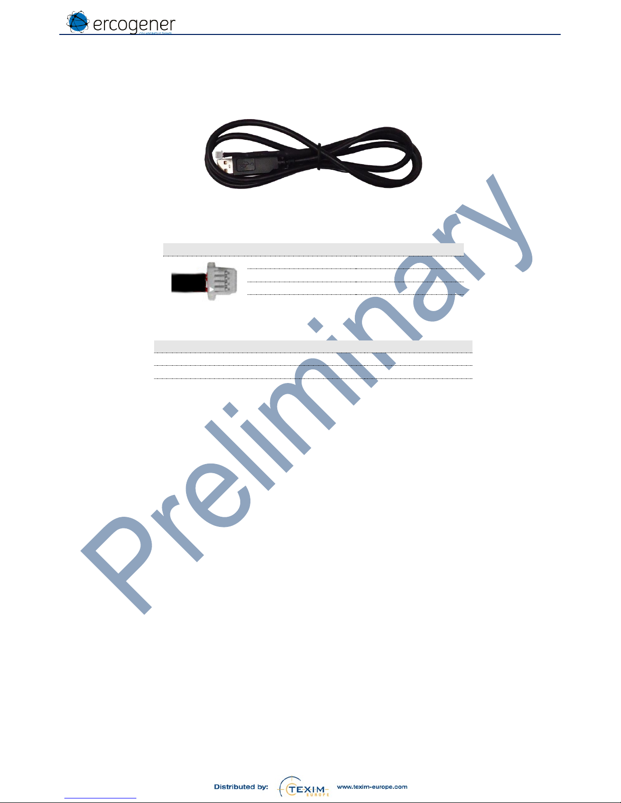
ANNEX 2 –USB –TTL 4-pin cable
(Ref. ERCOGENER : 4440Z00025)
Figure 5 : 4 pins female connector
Broche / Pin
4
TXD
3
RXD
2
no used
1
Gnd
Table 10 : Characteristics of 8-wire cable
Component
Characteristics
Connector 1
USB type A male
Cable
Lg ≈ 1.8m Ø 5 mm
Connector 2
4 pts serial SH
Page 34

EG-IoT_UG_demonstrator_006_UK.docx
Page 34 / 34
Descriptions and non-contractual illustrations in this document are given as an indication only. ERCOGENER SAS reserves the right to make any
modifications. This document is the property of ERCOGENER SAS. It may not be reproduced or disclosed to a third party without the written
consent of ERCOGENER SAS.
ANNEX 3 – GSM (RSSI/QUAL) LTE (RSRQ/RSRP)
GSM RSSI (Received Signal Strength Indication)
0
Below -110.5 dBm
1..30
From -110.5 dBm to -51 dBm
31
Over -51 dBm
99
Unknown or not detectable
GSM QUALity
2G – CSD data / GPRS
2G - EGPRS
3G - UMTS
Bit Error Rate
Bit Error Probability
Energy per Chip/Noise
0
BER < 0.2%
28 <= BEP <= 31
ECNo >= 44
1
0.2% < BER < 0.4%
24 <= BEP <= 27
38 <= ECNo < 44
2
0.4% < BER < 0.8%
20 <= BEP <= 23
32 <= ECNo < 38
3
0.8% < BER < 1.6%
16 <= BEP <= 19
26 <= ECNo < 32
4
1.6% < BER < 3.2%
12 <= BEP <= 15
20 <= ECNo < 26
5
3.2% < BER < 6.4%
8 <= BEP <= 11
14 <= ECNo < 20
6
6.4% < BER < 12.8%
4 <= BEP <= 7
8 <= ECNo < 14
7
BER > 12.8%
0 <= BEP <= 3
ECNo < 8
99
Unknown or not detectable
LTE - RSRQ (Reference Signal Received Quality)
0
Below -19 dB
1..33
From -19.5 dB to -3.5 dB pitch of 0.5 dB
34
Over -3 dB
255
Unknown or not detectable
LTE - RSRP (Reference Signal Received Power)
0
Below -141 dBm
1..96
From -140 dBm to -45 dBm pitch of 1 dBm
97
Over -44 dBm
255
Unknown or not detectable
Page 35
Contact details
The Netherlands
Germany North
Nordic region
Belgium
Germany South
UK & Ireland
Austria
Elektrostraat 17
NL-7483 PG Haaksbergen
T: +31 (0)53 573 33 33
F: +31 (0)53 573 33 30
E: nl@texim-europe.com
Bahnhofstrasse 92
D-25451 Quickborn
T: +49 (0)4106 627 07-0
F: +49 (0)4106 627 07-20
E: germany@texim-europe.com
Sdr. Jagtvej 12
DK-2970 Hørsholm
T: +45 88 20 26 30
F: +45 88 20 26 39
E: nordic@texim-europe.com
Zuiderlaan 14 bus 10
B-1731 Zellik
T: +32 (0)2 462 01 00
F: +32 (0)2 462 01 25
E: belgium@texim-europe.com
Martin-Kollar-Strasse 9
D-81829 München
T: +49 (0)89 436 086-0
F: +49 (0)89 436 086-19
E: germany@texim-europe.com
St. Mary’s House, Church Lane
Carlton Le Moorland
Lincoln LN5 9HS
T: +44 (0)1522 789 555
F: +44 (0)845 299 22 26
E: uk@texim-europe.com
Warwitzstrasse 9
A-5020 Salzburg
T: +43 (0)662 216 026
F: +43 (0)662 216 026-66
E: austria@texim-europe.com
General information
info@texim-europe.com
www.texim-europe.com
 Loading...