

Page 1

Page 2

2
Congratulations on your purchase of the eRC J-5 Cub Trainer. You’re about
to embark on an exciting and addictive adventure into model aviation. This
J-5 Cub is designed for beginners and not only flys great, but looks like the
real thing too. It comes with everything you need to teach yourself to fly and
you’ll learn basic terminology along the way as well as how to assemble the
plane, and how to fly it. The J-5 Cub is unique in that once you learn the
basics of flying the beginner 3-channel control setup, it can be converted to a
4-channel intermediate control setup for more fun. Please read the
instructions carefully and remember to have fun!
Glossary of Terms
Transmitter – The box you hold to control the plane.
Receiver – Receives the signal from the transmitter to control the plane.
ESC – the electronic speed controller is what makes the motor spin.
Vertical Stabilizer – The vertical fin on the back of the fuselage. The
moveable surface is called the rudder.
Horizontal Stabilizer – The horizontal fin on the back of the fuselage. The
moveable surface is called the elevator.
Rudder – Move the rudder to steer on the ground and in the air. Applying
right rudder will roll the plane into a right hand bank and make the plane turn
to the right.
Elevator – Move the elevator to make the nose point up or down. With
sufficient speed, applying back elevator will cause the plane to climb.
Ailerons – Moveable surfaces on the wing. Used in 4-channel control will
cause the plane to bank and turn. Rolls the plane faster than rudder.
Servo – Controls the movement of the control surfaces. Connects to the
receiver with a 3-wire plug.
Washout – Where the wing is twisted so that the trailing edge (back part of
the wing) is raised near the wing tips. Makes the airplane more stable.
Dihedral – The wing forms a shallow V shape when viewed from in front or
behind. The wing tips are higher than the center of the wing. This makes the
airplane very stable and allows the rudder to roll the wing into a bank.
Control Horn – Plastic part that is attached to a control surface near the
hinge line. Has several hole positions for a clevis to attach to.
Control Surface – The parts that move to control the airplane such as the
rudder, elevator, and ailerons.
Pushrod – The metal wire that connects the servo to the control surface.
Clevis – Plastic piece that threads on to a pushrod and clips on to a control
horn.
Page 3

3
Safety Statement
1. This is not a toy. You are responsible for the safe operation of this model
and any damage or harm it may cause.
2. Before flying the J-5 Cub for the first time please read through the
instructions carefully and make sure that your radio equipment is working
properly.
3. Young people under the age of 14 should only be permitted to operate this
model under the instruction and supervision of an adult.
4. Please keep these instructions for future reference after completing model
assembly. They contain information critical to the safe operation of this
model.
5. If you have any further questions regarding the safe operation of your RC
model, please contact your local hobby shop, flying club or Hobby-Lobby
International for professional help and advice.
Safety Precautions
Please read this section and follow all recommendations
1. Do not fly in strong wind or bad weather.
2. Never fly the model in crowded areas where there are lots of people,
automobiles on the road or power lines overhead. Do not fly near full-scale
airports.
3. Make sure that you have enough open area for flying as the model can
travel at a high rate of speed and cover a lot of area quickly. Initial flights
should be made in an area with a minimum size of a football field.
4. When charging the LiPo batteries, always charge them on a non-flammable
surface and monitor the charge process. Improper charging of LiPo batteries
is dangerous and can lead to a fire!
5. The J-5 Cub is made from EPO foam and plastic. These materials are
flammable and can be damaged by high heat. Never leave your J-5 Cub
near a heat source or in an automobile.
6. Do not attempt to catch your J-5 Cub while flying.
7. Never leave your J-5 Cub unattended when ready for flight.
Note: When preparing for flight, always turn on your transmitter
first and make sure that your throttle is in the off position prior
to plugging in the flight battery. Failure to follow this step may
lead to unintended motor start and damage to the model.
Page 4
4
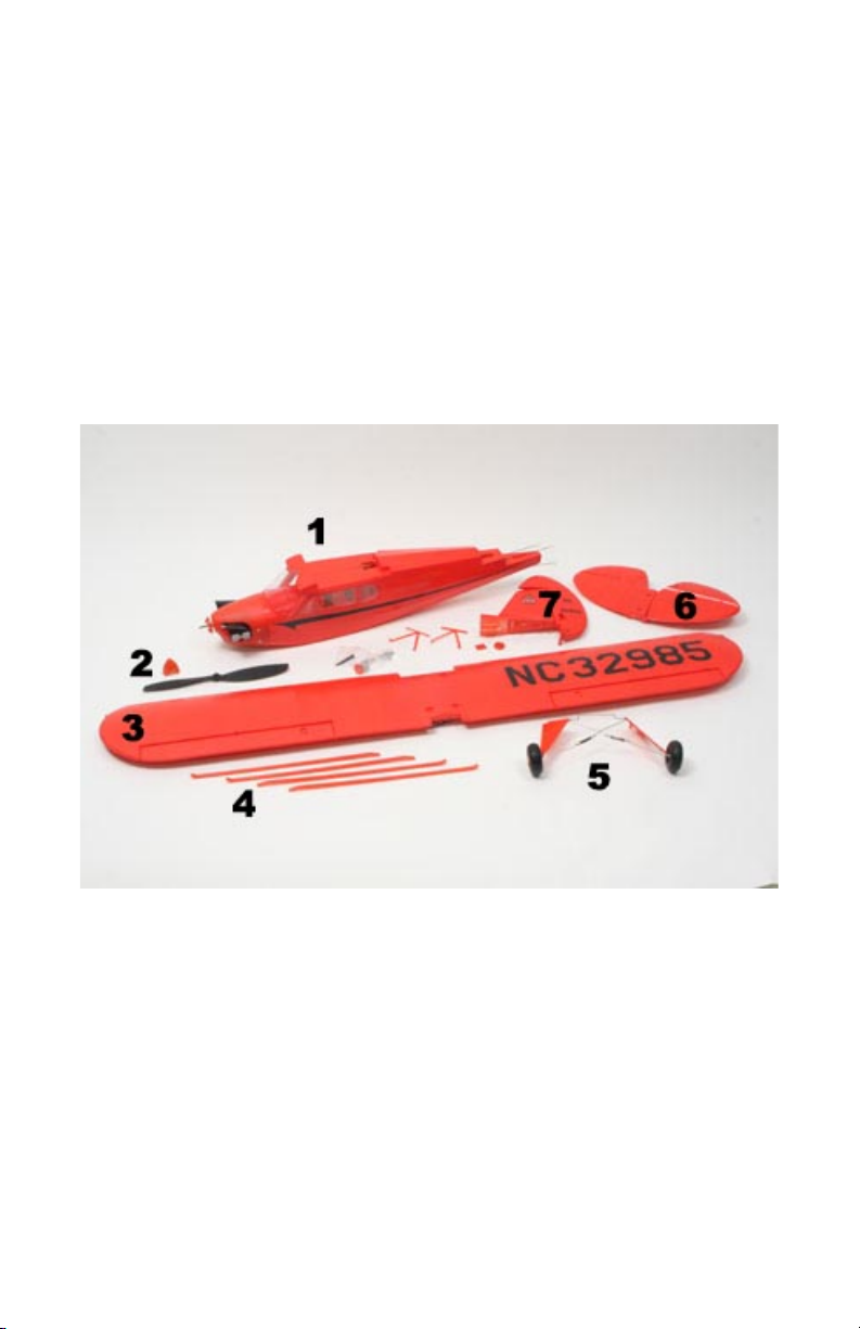
Assembly
Open the box and carefully remove all the parts.
1. Fuselage
2. Propeller/Spinner
3. Wing
4. Wing Struts
5. Landing Gear
6. Horizontal Stabilizer/Elevator
7. Vertical Stabilizer/Rudder
Page 5
5
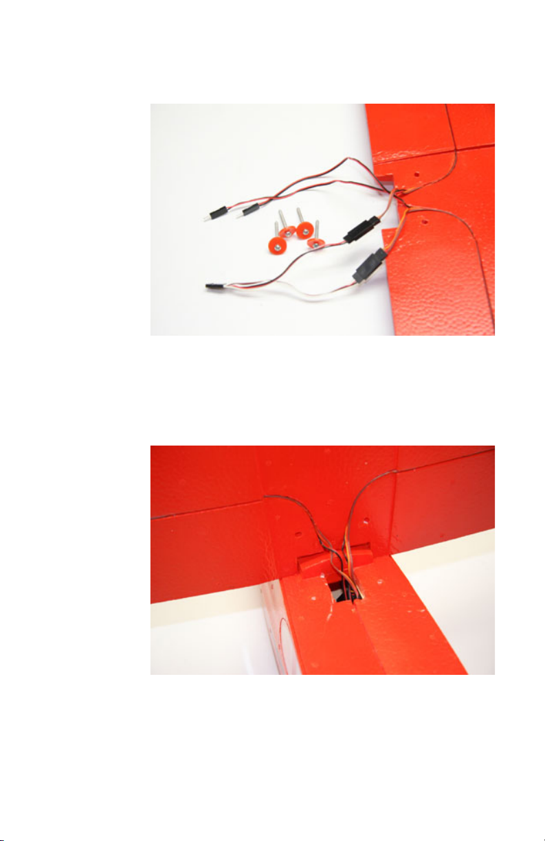
Attaching the Wing
1. Find the 4 long screws and the 4 orange plastic washers.
2. Hold the wing near the top of the fuselage and push all the wires into
the hole.
Page 6
6
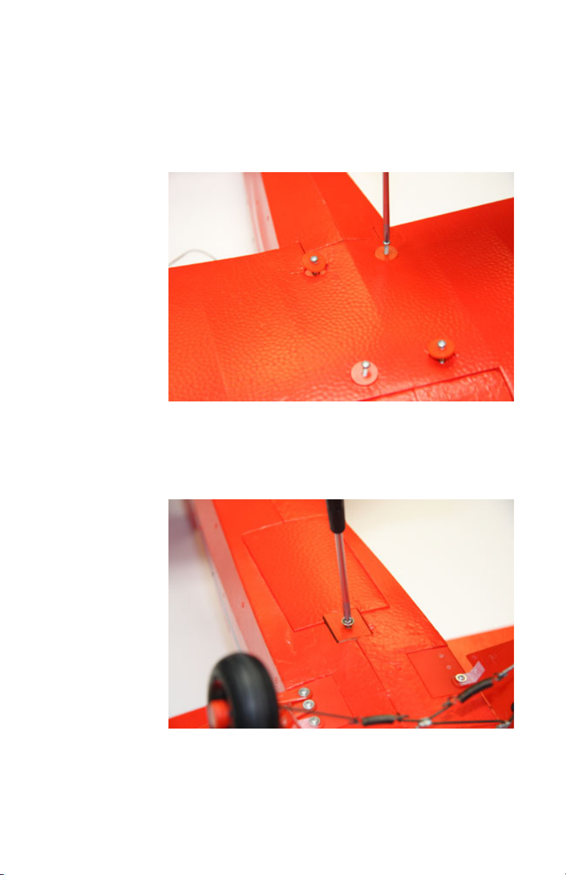
3. Set the wing on top of the fuselage and make sure all the wires go
into the hole. Use the included screwdriver to secure the wing to the
fuselage. Make sure the wing is tight to the fuselage and does not
wiggle. There should be some slight compression to the washers in
the wing.
4. Now flip the plane upside down and use a screwdriver to remove the
radio hatch.
Page 7
7
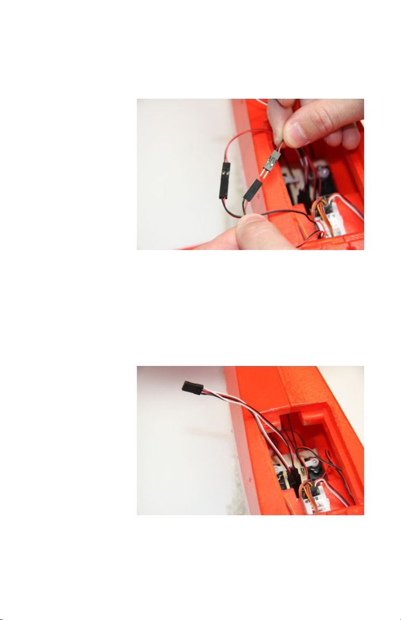
5. Use a small pair of pliers or a metal rod with a hook to carefully pull
the wires for the wing through. Find both of the matching 2-pin
connectors with red and black wires and plug them together making
sure the wires match colors. These are the connectors for the
navigation lights on the wing tips.
6. The aileron servo connector shown will not be used until you are
ready to convert the J-5 to 4-channels, more on that later. Make sure
that you tuck the connector into an area where it will not come loose
or interfere with the servos. The J-5 comes with the receiver preconnected for 3-channel operation. In this configuration, the servo
that operates the rudder is plugged into the aileron channel of the
receiver.
Page 8

8
Attaching the Wing Struts
7. Start with one side of the wing by locating two long struts, the strut
connector, and 8 screws.
8. The struts are identical and have ends with short tabs and ends with
longer tabs. Use two screws and attach the longer tab end of the
struts to the fuselage. Use the two holes nearest the back of the
plastic mounting plate as seen in the photo. The front holes will be
used to attach the landing gear in a later step. At this point, you’re
halfway to your first flight.
Page 9
9
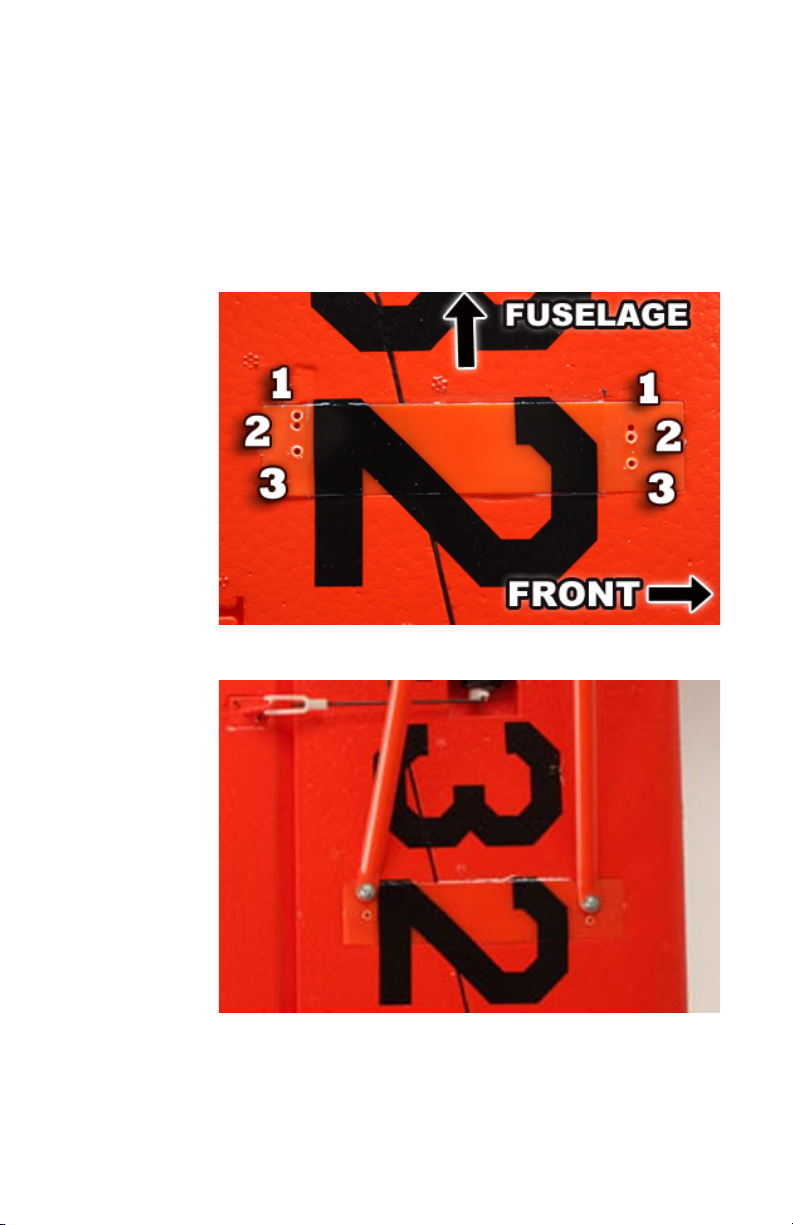
9. Note the different strut position holes on the wing. For the beginner
3-channel setting, you will attach the front strut to hole #2 on the right
hand side nearest the front of the wing using the provided screws.
Attach the back strut to hole #1 on the left hand side nearest the
back of the wing. This will create the most dihedral in the wing and
add washout to the wing tips. That will enable a more stable, easier
to fly airplane. The other settings will be discussed later for more
advanced 4-channel flying.
Page 10
10
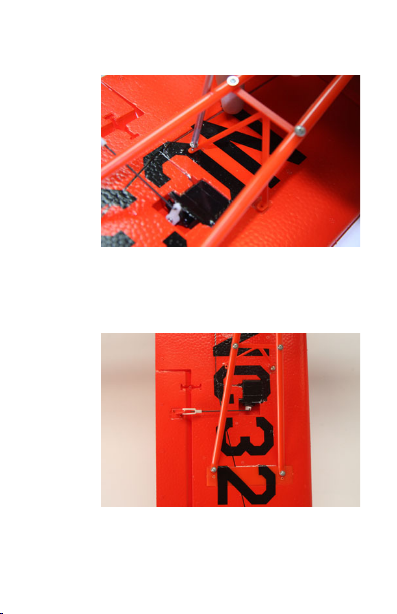
10. Use the screws provided to secure the strut connector to the wing
and to attach the strut connector to the strut. Do this on both
sides of the wing.
11. The completed strut assembly should look like the photo below.
Repeat these steps for the other wing.
Page 11

11
Attaching the Tail
12. Trial fit the Vertical Stabilizer and Horizontal Stabilizer. These are
parts 6 and 7 from the parts listing. Note how they key into each
other. Place them onto the fuselage as seen in the photo.
13. Screw the tail wheel bracket in place using the long screws
provided. The screws will go through the fuselage, the horizontal
stabilizer, and into the bottom of the vertical stabilizer. Attach the
springs as seen in the photo below. Connect the pushrod clevises
to the elevator control horns in the outermost hole.
Page 12

12
14. Connect the rudder pushrod clevis to the rudder control horn using
the outermost hole. You’re almost done now.
Installing the Landing Gear
15. Push the landing gear into the slot just behind the battery hatch.
Insert the plastic keeper and secure with a screw.
16. Screw the landing gear plastic fairings to the fuselage.
Page 13

13
Installing the Prop
17. Locate the prop, spinner, washer, nut and 2 screws.
18. First, slide the spinner back plate onto the motor shaft. Then put
the propeller on so that the raised lettering on it faces forward.
Next slide the washer on the shaft followed by the nut.
19. Tighten the nut with a pair of pliers to secure the prop.
Page 14

14
20. Install the spinner with the two screws provided.
Finishing Up
21. Re-install the radio compartment cover.
22. Install the battery into the battery hatch in the nose of the airplane
and secure using the latch.
Page 15

15
Your airframe is now complete. You did it! Take a minute and admire
the beautiful model that you just put together. Take a photo and post
it on forum at http://forums.hobby-lobby.com
Preparing for Flight
Battery Charging and Care
You must first charge your
flight battery before flying.
Plug the charger into a 110V
wall outlet. This charger can
be used with 2 and 3 cell lipo
batteries. The J-5 Cub uses a
2 cell lipo battery. The battery
comes with two sets of wires
and connectors. The set with
the white plug and 3 wires is
the charging lead. Connect the battery charge lead into the matching
connector on the charger. 2 of the lights on the charger will turn red
to indicate charging. It will take approximately 2 hours for the battery
to fully charge. Once fully charged, the red lights on the charger will
turn green to indicate that it is done. Flight times are approximately
10 minutes per charge.
Page 16

16
Safety Instructions for charging and using Lipo batteries.
• Do not put the battery on, or near anything, that can catch fire.
• Charge the battery on a non-flammable base, i.e. a metal tray.
• Do not disassemble the battery.
• Do not short-circuit the battery.
• Do not use, or leave, the battery near a fire, stove or heated place.
• Do not immerse the battery in water or seawater.
• Do not charge the battery near a fire or under the blazing sunlight.
• Do not impact or throw the battery.
Center of Gravity
The Center of Gravity or “CG” is important for your airplane to fly
properly. If the CG is too far forward or “nose heavy”, the model will
have difficulty climbing and handle poorly. If the CG is too far back or
“tail heavy”, the model is unstable and extremely difficult to control.
The J-5 should balance at a point that is around 2-1/2” (63mm) back
from the leading edge of the wing. Measure 2-1/2” back from the
front of the wing near the fuselage and both wings and make a mark.
Put your index fingertips on the mark and pick up the model. The
fuselage should stay level and not drop the nose or the tail quickly.
The model as built in its stock configuration will balance correctly and
no adjustments are needed. If you make any changes to the airplane
or use a different battery the CG may be affected. You will need to
make sure the model balances correctly and use lead weight if
necessary.
Page 17

17
Control Surface Check
Note: For Receiver-Ready version, use your radio manual for proper setup.
Turn the transmitter on and move the throttle stick to the low throttle
position. The left hand stick controls throttle. The right hand stick
controls elevator (forward/backward) and rudder (left/right).
Install the flight battery and plug it into the matching connector inside
the fuselage. Be very careful at this time as the motor is armed but
not turning. If the throttle stick is moved up the propeller will turn.
Stay clear of the propeller at all times.
Page 18

18
Let’s ensure that the control surfaces move in the proper direction.
Stand behind the airplane with nose facing away from you. Move the
right stick to the right. The rudder should point to your right.
If the rudder moves to the left, you need to move the Ail switch on
the transmitter. Check again to ensure that moving the stick to the
right moves the rudder to the right.
Page 19

19
Next, move the right stick back. The elevator should point up.
If it points down, you need to move the Ele switch on the transmitter.
Check again to ensure that moving the stick backwards moves the
elevator up.
Now let’s center the control surfaces. The trim tabs on your radio
move the control surfaces a small amount. They are useful if the
surfaces are not quite centered when the main control stick is in the
neutral position. They are also handy while flying. For instance, if
your plane always turns to the left without any control input by you,
then you can move the trim tab to the right a little bit at a time until
the plane flys straight.
Page 20

20
Now look at the elevator and rudder.
They should appear level with the rest of the surface as seen in the
photo below. If the rudder or elevator is not level, center it with the
trim tabs. For instance, if the elevator is pointing down, you can
move the elevator trim tab to move the elevator up until it is level.
If it requires the trim tab to be moved all the way or almost all the
way to it’s maximum point, a mechanical adjustment will be
necessary. Move the trim tab back to center and follow the
instructions below.
For mechanical centering adjustment, unclip the control horn clevis
and rotate the clevis on the pushrod. Spin the clevis clockwise to
shorten the length or spin the clevis counter-clockwise to increase
the length.
Page 21

21
Control Throws
This section is for the receiver ready version. If you purchased
the Read-To-Fly J-5 with the radio included, skip down to the “At the
Field” section. The control surfaces should move the following
amounts for 3 and 4-channel setups.
Rudder – 5/8” (15mm) left and right
Elevator – 5/8” (15mm) up and down
Ailerons – 3/8” (10mm) up and down
Page 22

22
At the Field
When choosing a flying site, it is important to have plenty of space to
fly. Avoid areas with pedestrians, trees, buildings, cars, or power
lines. An area the size of a football field with no obstructions nearby
is perfect. Also make sure you fly in calm weather conditions. The
winds should be calm for your first flights. Learning to fly in rough
weather conditions reduces your chance for success and will likely
end up damaging your plane.
Flying Tips
Before getting in the air it is important to carefully read and remember these
flying tips.
1. ALWAYS take off and land with the nose pointing into the wind.
2. The right side stick controls Rudder and Elevator (3-Channel Setup).
3. The left side stick controls the throttle (3-Channel Setup).
4. Rudder input (left/right movement) causes the plane to turn.
5. Elevator input (forward/backward movement) causes the nose to pitch up or
down.
6. Throttle input (forward/backward movement) causes the motor to increase or
decrease in power.
7. Use short, small movements on the control stick.
8. Keep the plane within easy visual range.
9. Focus on keeping the wings and fuselage level to avoid diving or climbing
too sharply.
10. If you get disoriented or lose control, pull the power all the way off and try to
land. Crashing with full power will increase the amount of damage.
Page 23

23
Taking off
Your J-5 Cub can take to the air with a hand launch or an ROG (Rise
Off the Ground).
For hand launching, it is a good idea to have a second person help.
Turn on the transmitter first and then connect the flight battery. Hold
the plane level and above and to the side of your head while pointed
into the wind. Move the throttle stick forward to the full position.
Keep the plane level and firmly launch it straight ahead. Allow the
plane to gain some altitude before attempting to turn.
For ROG (Rise Off the Ground) launching, you’ll want a nice smooth
paved surface or a finely cut grass field. Place the plane on the
ground and pointed into the wind. Increase the throttle smoothly to
about 3/4 power. As the plane increases in speed apply a small
amount of backward movement to the elevator stick to take off.
Relax the elevator and allow the plane to gain some altitude before
attempting to turn.
Flying
Once you are at an altitude of about 50 feet (about as high as a tall
tree), you can reduce the throttle just enough to maintain level flight.
To make a turn, apply a small amount of rudder input, just enough to
start the turn, and then return the stick to neutral. Applying too much
rudder input or holding it too long could result in a dive. The elevator
controls the angle the plane flys at. Move the elevator stick backward
to climb and forward to dive. Applying too much elevator input or
holding it too long could result in a stall or excess speed. The
elevator/rudder stick should remain in the neutral position unless you
are turning or need to keep the plane flying straight and level.
If you are flying and notice the J-5 climbing, apply just enough
forward elevator control to return it to level flight. If the J-5 is diving,
apply just enough backward elevator control to return it to level flight.
Stay up high and practice making turns staying close within easy
visual range. You can try making left or right hand circles in the air.
Important: When the plane is flying towards you (nose pointing at
you) the left/right controls will appear to be reversed. Applying right
rudder will make the plane turn to your left. It takes some practice to
get used to this.
Page 24

24
Landing
That battery will last about 8-10 minutes and then it will be time to
land. Point the plane into the wind and reduce power until the model
slowly descends. At 2 feet off the ground, apply a small amount of
backward movement on the elevator stick to flare and allow the
plane to softly touch down. Once you touch down, move the throttle
stick all the way down. Do not attempt to catch the plane out of the
air. As you practice more, you’ll be able to land softly and right were
you planned.
Aerobatics
Once you are able to take-off, fly around under control, and land
safely, you’ll be ready to try some more advanced maneuvers. You
can perform a loop by going to full power, and pulling back on the
elevator and holding the elevator input until the model completes the
loop and returns to level flight. Use your imagination and come up
with your own stunts.
Repairing Crash Damage
Don’t feel bad. Sooner or later everyone who has flown a model
airplane has crashed. Consider it a rite of passage and an
opportunity to learn a new skill, like repairing your plane. The good
news is that your J-5 Cub is made of durable EPO foam and should
survive quite a bit of abuse. Should you break part of the wing or any
foam part, it can be glued back together using 5-minute epoxy or
regular CA glue. If the part is beyond repair, a complete line of spare
parts is available.
Page 25

25
4-Channel Control
After you’ve learned to fly around comfortably and land safely with
3-channel control (rudder, elevator, and throttle) you are ready to
add the ailerons and experience 4-channel flying. The following
instructions will guide you through the 4-channel setup process.
Enjoy.
Assembly
Use a sharp blade and cut the ends of the ailerons loose. Only cut
the material on either side of the aileron. Cut it to where there is a
1/8” in gap on the sides of the ailerons to the wing.
Page 26

26
It should look like this when done.
Remove the clevis that is attached to each aileron control horn. Now
you will need to move the ailerons up and down about 15 times to
work the hinges in. They will be stiff at first and should move freely
when done.
Now you will need to remove some of the dihedral. For the
intermediate 4-channel setting, move both struts to hole #3.
Page 27

27
Open the radio bay with a screwdriver. Remove the servo plug from
the #2 channel in the receiver and plug it into the #4 channel. This is
connected to the rudder servo. Now find the servo lead from the wing
that has not been connected. Plug it into the #2 channel in the
receiver. Make sure that all of the black and red wires all line up in a
row from plug to plug.
Replace the radio bay cover. Turn on the transmitter and plug in the
flight battery. Move the right hand stick to the right. The right aileron
should move up and the left aileron should move down.
Page 28

28
If the ailerons move backwards, change the position of the AIL
reverse switch on the face of the radio.
Now move the left hand stick to the right while standing behind the
plane. The rudder should move to the right.
If the rudder moves backwards, change the position of the RUD
reverse switch on the face of the radio.
Page 29

29
4-Channel Flying
You will find that flying with all 4 channels will give you greater
control and allow you to perform more aerobatics. The right hand
stick will still be used to turn the airplane. It does this by using the
ailerons now instead of the rudder to roll the plane into a bank. To
turn, move the right hand stick to the right or left to cause the wing to
bank, then pull back on the elevator to turn. The airplane will roll
quicker using the ailerons, so remember to give small stick inputs
until you get comfortable with how the plane reacts.
Once you get familiar with how it reacts you can try an aileron roll.
Get some altitude and while flying straight and level, pull back
elevator to point the nose up slightly. Return the elevator stick to
neutral and apply full right or left aileron. As the plane rolls to
inverted, you may need to apply some forward elevator to keep the
nose level. Once the plane returns to upright and level flight return
the aileron stick to neutral. The skills you learn on this J-5 Cub will be
transferable to nearly any other airplane you want to fly. Now get out
there and have some fun.
Page 30

30
Troubleshooting
Thanks for your eRC J-5 Cub purchase. This airplane and its components are warrantied to
be free from physical, mechanical, and electronic defects at the time of purchase. You
should check the mechanical operations and general physical condition of the airplane prior
to flying. Hobby Lobby continues to provide the best value for R/C products in the industry,
but cannot be responsible for, or warranty products that may have been damaged in user
related incidents beyond our control. If for any reason you are not satisfied with your
purchase, please send it back to us within 30 days. The airplane must be in new and
unused condition and in its original retail packaging. We are unable to reimburse for return
shipping costs, but there is no restocking fee for qualified returns. Returns accepted outside
of these guidelines will be subject to a 15% restocking fee.
Hobby Lobby International
(866) 512-1444
5614 Franklin Pike Circle
Brentwood, TN 37027
Warranty Information
Page 31

31
Spare Parts for ERC J-5 Cub
Part No
Description
Retail
ERC2201
J-5 Airframe Only
$129.99
ERC2210
7.4V 2S 1600mAH Lipo Battery
$19.99
ERC2202
Fuselage
$39.99
ERC2203
Main Wing Set
$27.99
ERC2206
Tail Wing Set (Rudder&Elevator)
$13.99
ERC2207
Cowl with Dummy Engine
$5.99
ERC2209
Brushless ESC (30A)
$32.99
ERC2211
Outrunner Motor (3130) 1300KV
$19.99
ERC2215
Propeller
$4.99
ERC2216
Main Landing Gear
$12.99
ERC2219
Water Slide Decals
$7.99
ERC2220
Control Horns/Clevises
$4.99
ERC2221
Motor Mount
$4.99
ERC2226
Spinner
$2.99
ERC2230
Scale Pilot
$5.99
ERC2231
Strut Set
$7.99
ERC2232
Tail Wheel Set
$4.99
Available from your local retail hobby shop or at www.hobby-lobby.com
Page 32

32
 Loading...